ATEN CE624 User Manual Download Page 26

CE624 / CE924 User Manual

18

(b) Plug the second supplied power adapter into a power source; then plug 
the adapter's power cable into the power jack located on the CE624R's rear 
panel.

10. For control of serial device and/or to use the WakeUp PC feature, connect 

a computer to the RS-232 serial port located on the CE624L’s rear panel.

11. For remote control purpose of the PC connected to the CE624L, connect a 

control system (ex. VK2100) to the RS-232 serial port located on the 
CE624R’s rear panel.

12. To extend video, RS-232 and USB signals up to 150 m with a resolution of 

1080p, set the long reach switch located on the CE624L and CE624R’s 
rear panel to ON (single view only). 

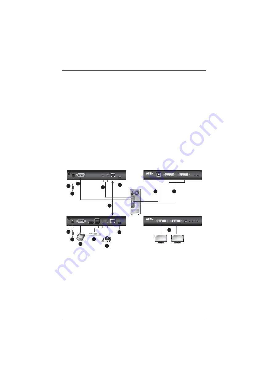
Installation Diagram

CE624L (Rear)

CE624L (Front)

CE624R (Rear)

CE624R (Front)

DVI Cables

USB Cable

LOCAL PC

6

4

3

7

5

2

8

12

12

10

11

Cat 5e/6 Cable

Audio Cables

1

9a

1

9b

Summary of Contents for CE624

Page 1: ...USB DVI Dual View HDBaseT 2 0 KVM Extender CE624 USB DisplayPort Dual View HDBaseT 2 0 KVM Extender CE924 User Manual www aten com...

Page 2: ...f the FCC Rules Operation is subject to the following two conditions 1 this device may not cause harmful interference and 2 this device must accept any interference received including interference tha...

Page 3: ...defective following their purchase the buyer and not the manufacturer its distributor or its dealer assumes the entire cost of all necessary servicing repair and any incidental or consequential damag...

Page 4: ...1 CE924R USB DisplayPort Dual View HDBaseT 2 0 KVM Extender Remote Unit 2 DisplayPort Cables 1 5 m 1 USB Type A to USB Type B Cable 1 8 m 1 Microphone Cable 1 8 m 1 Speaker Cable 1 8 m 2 Power Adapter...

Page 5: ...tion Overview 1 Features 2 Requirements 3 Console 3 Computers 3 Cables 3 Maximum Cable Distances 4 Maximum Resolution with Cable Distances 4 Components 5 CE624L Local Unit Front and Rear View 5 CE624R...

Page 6: ...CE624 CE924 User Manual vi Long Reach Mode 21 Appendix Safety Instructions 23 General 23 Mounting 25 Technical Support 26 International 26 North America 26 Specifications 27 Limited Warranty 29...

Page 7: ...1 Introduction introduces you to the CE624 CE924 system Its purpose features and benefits are presented and its front and back panel components are described Chapter 2 Hardware Setup describes the ste...

Page 8: ...n Indicates keys you should press For example Enter means to press the Enter key If keys need to be chorded they appear together in the same bracket with a plus sign between them Ctrl Alt 1 Numbered l...

Page 9: ...sole where it is conveniently accessible but you want the equipment to reside in a safe location away from the dust and dirt of the factory floor or the harsh environmental influence of a construction...

Page 10: ...terminal or serial devices such as touch screens and barcode scanners USB 2 0 supports transparent USB 2 0 signals and true plug and play no software or drivers required Supports Long Reach mode for t...

Page 11: ...I ports CE624 only Two DisplayPort ports CE924 only 2 USB ports for the mouse and keyboard RS 232 Serial port optional Microphone and speaker ports optional Cables For optimal signal integrity and to...

Page 12: ...R 100 m Remote Unit CE624R to monitor 5 m Connection Distance Computer to Local Unit CE924L 1 8 m Local Unit CE924L to Remote Unit CE924R 100 m Remote Unit CE924R to monitor 1 8 m Model Input Port Out...

Page 13: ...grounding terminal Grounds the unit to prevent damages from power surges or static electricity 6 power jack The cable from the power adapter connects here 7 RS 232 serial port This RS 232 serial port...

Page 14: ...re upgrade switch Put the switch to ON to enable the firmware upgrade mode Note The firmware upgrade mode is reserved for technical support To upgrade the device s firmware please contact ATEN custome...

Page 15: ...ge 21 for more information 6 grounding terminal Grounds the unit to prevent damages from power surges or static electricity 7 power jack The cable from the power adapter connects here 8 RS 232 serial...

Page 16: ...are upgradeswitch Put the switch to ON to enable the firmware upgrade mode Note The firmware upgrade mode is reserved for technical support To upgrade the device s firmware please contact ATEN custome...

Page 17: ...ck The cable from the power adapter connects here 7 RS 232 serial port This RS 232 serial port is for connecting to a serial terminal for configuration 8 audio ports These mini stereo ports connect to...

Page 18: ...ormation 5 power LED Indicates the unit is receiving power see page 21 for more information 6 grounding terminal Grounds the unit to prevent damages from power surges or static electricity 7 power jac...

Page 19: ...long reach mode see Long Reach Mode page 21 13 firmware upgrade switch Put the switch to ON to enable the firmware upgrade mode Note The firmware upgrade mode is reserved for technical support To upgr...

Page 20: ...CE624 CE924 User Manual 12 This Page Intentionally Left Blank...

Page 21: ...h this package and stick them onto the switch s bottom panel at the corners as shown in the diagram below Note The unit used in the diagram below is CE924 the procedure for connecting the CE624 is ide...

Page 22: ...unt a unit do the following Note The unit used in the diagram below is CE924 the procedure for connecting the CE624 is identical 1 Using the screws provided in the mounting kit screw the mounting brac...

Page 23: ...iagram below is CE924 the procedure for connecting the CE624 is identical 1 Use a grounding wire to ground both units by connecting one end of the wire to the grounding terminal and the other end of t...

Page 24: ...CE624 CE924 User Manual 16 Cat 5e 6 6a cable...

Page 25: ...nd of the cable into a USB Type A port on the local computer 4 Connect both DVI connectors of the supplied DVI cables to the DVI D input ports located on the CE624L s front panel Connect the other end...

Page 26: ...s rear panel 11 For remote control purpose of the PC connected to the CE624L connect a control system ex VK2100 to the RS 232 serial port located on the CE624R s rear panel 12 To extend video RS 232 a...

Page 27: ...USB Type A port on the local computer 4 Connect both DisplayPort connectors of the supplied DisplayPort cables to the DisplayPort input ports located on the CE924L s front panel Connect the other end...

Page 28: ...rear panel 11 For remote control purpose of the PC connected to the CE924L connect a control system ex VK2100 to the RS 232 serial port located on the CE924R s rear panel 12 To extend video RS 232 an...

Page 29: ...on the rear of the local or remote unit set either one of the long reach switch to ON Note The unit used in the diagram below is CE924 the procedure for connecting the CE624 is identical LED Indicatio...

Page 30: ...CE624 CE924 User Manual 22 This Page Intentionally Left Blank...

Page 31: ...unless adequate ventilation has been provided Never spill liquid of any kind on the device Unplug the device from the wall outlet before cleaning Do not use liquid or aerosol cleaners Use a damp cloth...

Page 32: ...as been exposed to rain or water The device has been dropped or the cabinet has been damaged The device exhibits a distinct change in performance indicating a need for service The device does not oper...

Page 33: ...ut of a rack the slide rails can pinch your fingers After a device is inserted into the rack carefully extend the rail into a locking position and then slide the device into the rack Do not overload t...

Page 34: ...y beforehand Product model number serial number and date of purchase Your computer configuration including operating system revision level expansion cards and software Any error messages displayed at...

Page 35: ...Firmware Upgrade Long Reach 2 x 2 Segment Switch 2 x 2 Segment Switch LEDs Power 1 Green 1 Green Link 1 Orange 1 Orange Video Out 1 N A 1 Orange Video Out 2 N A 1 Orange USB Transfer Rate USB 2 0 Up...

Page 36: ...ong Reach Mode Switch 1 x Slide Switch 1 x Slide Switch Firmware Upgrade Switch 1 x Slide Switch 1 x Slide Switch LEDs Power 1 Green 1 Green Link 1 Orange 1 Orange Video Out 1 N A 1 Orange Video Out 2...

Page 37: ...de a repair service without charge during the Warranty Period If a product is detective ATEN will at its discretion have the option to 1 repair said product with new or repaired components or 2 replac...

Reviews: