ATEN CE600 User Manual Download Page 15

Chapter 1. Introduction

7

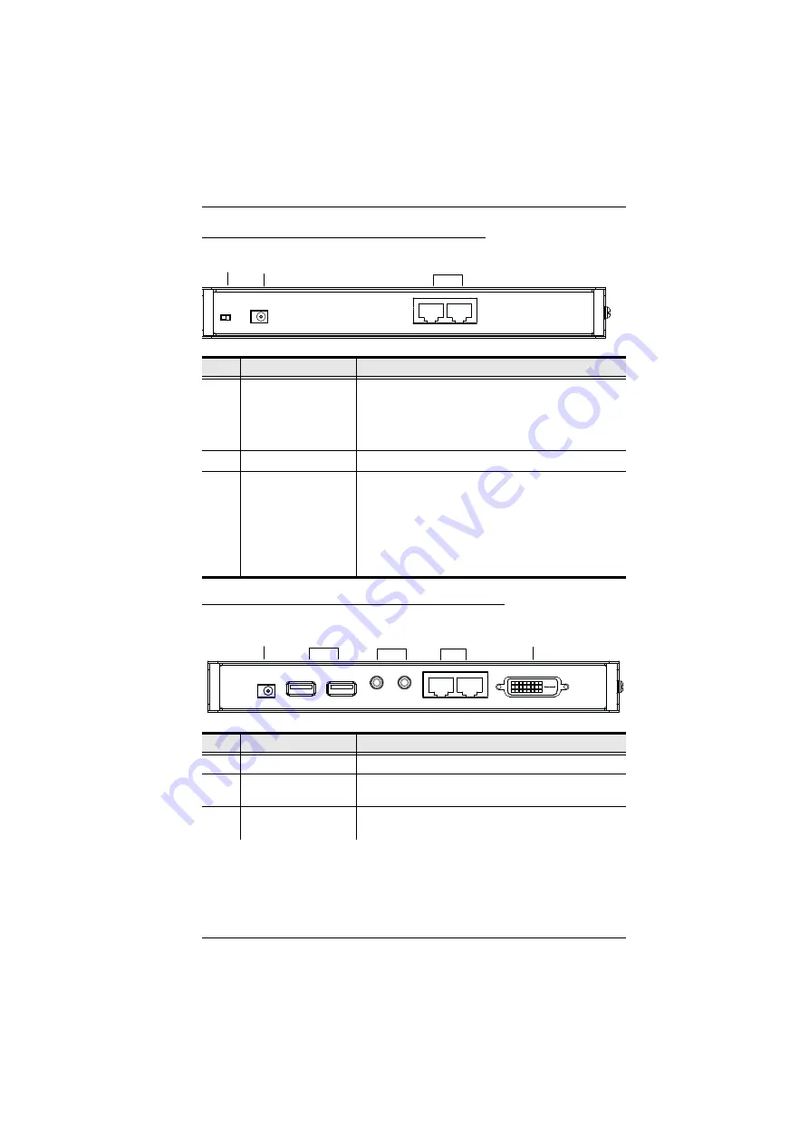
CE600L / CE602L (Local Unit) Rear View

CE600R / CE602R (Remote Unit) Rear View

No. 

Component

Description

1

F/W Upgrade Switch

Use this switch to turn on the firmware upgrade mode. 
Reset the power to proceed with the firmware 
upgrade.

Switch it off and reset the power to return to normal 
mode.

2

Power Jack

The cable from the DC Power adapter connects here.

3

Sub / Main

The Cat 5e cable that connects the Remote and Local 
Units plugs in here.

Dual Link DVI 

(CE602 only)

uses 2 cables

Single Link DVI: 

uses 1 cable (Main-to-Main)

(Note: If HDCP, RS-232, microphone and dual link 
signals are needed, the Sub cable must be 
connected.)

No. 

Component

Description

1

Power Jack

The cable from the USB Power adapter connects here.

2

USB

The USB cable for your keyboard / mouse plugs in 
here.

3

Audio Ports

These mini stereo ports are for the speakers (green) 
and microphone (pink).

3

1

2

1

3

4

5

2

Summary of Contents for CE600

Page 1: ...DVI KVM Extender CE600 CE602 User Manual www aten com...

Page 2: ...ble protection against harmful interference when the equipment is operated in a commercial environment This equipment generates uses and can radiate radio frequency energy and if not installed and use...

Page 3: ...f this system is not responsible for any radio and or TV interference caused by unauthorized modifications to this device It is the responsibility of the user to correct such interference The manufact...

Page 4: ...u encounter a problem contact your dealer Read this manual thoroughly and follow the installation and operation procedures carefully to prevent any damage to the unit and or any of the devices connect...

Page 5: ...s 3 Cables 3 Operating Systems 4 Components 5 CE600L CE602L Local Unit Front View 5 CE600R CE602R Remote Unit Front View 6 CE600L CE602L Local Unit Rear View 7 CE600R CE602R Remote Unit Rear View 7 2...

Page 6: ...CE600 CE602 User Manual vi Appendix Safety Instructions 25 General 25 Rack Mounting 27 Technical Support 28 International 28 North America 28 Specifications 29 Troubleshooting 30 Limited Warranty 30...

Page 7: ...atures and benefits are presented and its front and back panel components are described Chapter 2 Hardware Setup describes the steps that are necessary to quickly and safely set up your installation C...

Page 8: ...n Indicates keys you should press For example Enter means to press the Enter key If keys need to be chorded they appear together in the same bracket with a plus sign between them Ctrl Alt 1 Numbered l...

Page 9: ...systems The CE600 uses one Cat 5e cable DVI Single Link to support up to 1920 x 1200 video resolution The CE602 can support up to 2560 x 1600 DVI Dual Link resolution and requires a second Cat 5e cabl...

Page 10: ...e two Cat 5e cables must be the same Manual compensation control to adjust signal strength in order to compensate for distance RS 232 serial ports connect to a serial terminal or serial devices such a...

Page 11: ...tional Cables For optimal signal integrity and to simplify the layout we strongly recommend that you use the high quality custom KVM Cable that is provided with this package Cat 5e cable is required t...

Page 12: ...s Supported operating systems are shown in the table below OS Version Windows 2000 2003 2008 XP Vista 7 Linux RedHat 9 0 and higher SuSE 10 11 1 and higher Debian 3 1 4 0 Ubuntu 7 04 7 10 UNIX FreeBSD...

Page 13: ...2 USB Type B Input The USB cable from your computer or USB hub plugs in here 3 Audio Ports These mini stereo ports are for the speakers green and microphone pink 4 RS 232 Serial Port Connect the RS 2...

Page 14: ...ription 1 EQ Switch Use this to adjust the video quality of the remote console 2 RS 232 Serial Port RS 232 serial devices such as touchscreens or barcode scanners plug into this port 3 LEDs The CE602R...

Page 15: ...DC Power adapter connects here 3 Sub Main The Cat 5e cable that connects the Remote and Local Units plugs in here Dual Link DVI CE602 only uses 2 cables Single Link DVI uses 1 cable Main to Main Note...

Page 16: ...ts plugs in here Dual Link DVI CE602 only uses 2 cables Single Link DVI uses 1 cable Main to Main Note If HDCP RS 232 microphone and dual link signals are needed the Sub cable must be connected 5 DVI...

Page 17: ...bracket into the top or bottom of the unit as show in the diagram below 1 Important safety information regarding the placement of this device is provided on page 25 Please review it before proceeding...

Page 18: ...CE600 CE602 User Manual 10 2 Screw the bracket into any convenient location on the rack Note These screws are not provided We recommend that you use M5 x 12 Phillips Type I cross recessed type screws...

Page 19: ...the two grounding wires supplied with this package to ground both units by connecting one end of the wire to the grounding terminal and the other end of the wire to a suitable grounded object 2 Make...

Page 20: ...wire Solder this wire to the RJ 45 connector as shown in the diagram below b The second method is to use the STP cable shielding for grounding In this case make sure that the shielding makes tight co...

Page 21: ...232 serial port on the local unit to a serial port on the local computer 4 Plug either end of the Cat 5e cable into the CE600L CE602L s Sub Main ports Plug the other end of the Cat 5e cable into the S...

Page 22: ...CE600 CE602 User Manual 14 Installation Diagrams Front View 1 DVI KVM cable Local PC 3 2...

Page 23: ...CE602L connects to the computer the serial port on the CE600R CE602R not shown connects to a serial device optional 2 The illustration above shows a Dual Link DVI installation where both Cat 5e cable...

Page 24: ...CE600 CE602 User Manual 16 This Page Intentionally Left Blank...

Page 25: ...play The CE600 CE602 Local and Remote Units have front panel LEDs to indicate their operating status as shown in the tables following CE600L CE602L Local Units LED Indication Link Green Lights steadil...

Page 26: ...it LED Indication Link Green Lights steadily to indicate that the connection to the Local Unit is ok Flashes when there is a problem with the connection to the Local Unit Power Green Lights steadily t...

Page 27: ...http www aten com Before You Begin To prepare for the Firmware Upgrade do the following 1 Using a computer connected to the Local Unit go to our Internet support site and choose the model name of you...

Page 28: ...W Upgrade switch On This enables both the Local and Remote Units to operate in Firmware Upgrade Mode when the Local Unit is powered on again 6 Plug in the Local Unit s power adapter to power it on CE6...

Page 29: ...ening a command line and entering the full path to it The Firmware Upgrade Utility Welcome screen appears Note The screens shown in this section are for reference only The wording and layout of the ac...

Page 30: ...n is higher than the upgrade version it brings up a dialog box informing you of the situation and gives you the option to Continue or Cancel If you did not enable Check Firmware Version the Utility in...

Page 31: ...y 2 After successfully upgrading the firmware unplug the Local unit s power adapter 3 Turn the FW Upgrade switch Off to exit the Firmware Upgrade Mode for both Local and Remote Units 4 Plug in the Loc...

Page 32: ...CE600 CE602 User Manual 24 This Page Intentionally Left Blank...

Page 33: ...rovided Never spill liquid of any kind on the device Unplug the device from the wall outlet before cleaning Do not use liquid or aerosol cleaners Use a damp cloth for cleaning The device should be ope...

Page 34: ...ints or short out parts resulting in a risk of fire or electrical shock Do not attempt to service the device yourself Refer all servicing to qualified service personnel If the following conditions occ...

Page 35: ...out of a rack the slide rails can pinch your fingers After a device is inserted into the rack carefully extend the rail into a locking position and then slide the device into the rack Do not overload...

Page 36: ...lease have the following information ready beforehand Product model number serial number and date of purchase Your computer configuration including operating system revision level expansion cards and...

Page 37: ...A RS 232 1 x DB 9 Female Black 1 x DB 9 Male Black Power 1 x DC Jack Black Sub Main 2 x RJ 45 Female Black LEDs LINK 1 Green 1 Green POWER 1 Green 1 Green Switches EQ Switch N A 1 x 8 position switch...

Page 38: ...fresh rate Limited Warranty IN NO EVENT SHALL THE DIRECT VENDOR S LIABILITY EXCEED THE PRICE PAID FOR THE PRODUCT FROM DIRECT INDIRECT SPECIAL INCIDENTAL OR CONSEQUENTIAL DAMAGES RESULTING FROM THE US...

Reviews: