Rev.02-06/25/12
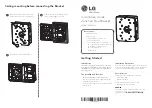
Figure 1
Figure 2
Step 1: Mount Frame to Wall
Scribe a horizontal line on the
wall showing the exact location
of the top edge of the upper left
LCD
monitor will be. Measure
down 8.8” (223.5mm) from that
line and scribe another
horizontal line showing where
the first location of the
adjustable lag bolts for the
mounting frame will be. This is
for the top left keyhole slot
(Figure 1).
Scribe a vertical line showing
where the left side of the upper
LCD monitor will be. Measure to
the right and scribe another
vertical line 12.6” (320mm) to
locate the location of the first
adjustable lag bolts for the
mounting frame will be. This is for the top right keyhole slot
(
Figure 1).
Mark where the 2
nd
horizontal line vertical lines meets.
Measure 55.7” (1414.8mm) to the right for next location of the
adjustable lag bolt. Use a level then mark the second location,
use level to make sure it Is horizontally level to the first hole
on the left side. Pre-drill the marked locations using a 3/16”
(5mm) drill
(Figure 1).
Install the adjustable lag bolts to the pre-drilled holes then
hang the frame onto the two adjustable studs. Install the flat
washer and hex nut to secure frame to wall. Hand tighten hex
nut only
(Figure 2)
.
Step 3:
Mark the location for the other adjustable lag
bolts, one upper center keyhole, three bottom
keyholes slots and three center middle holes
(Figure 3).
Step 4:
Remove the two nuts and washer securing the
frame to the wall and place the frame back on
the floor. Pre-drill all the marked locations
using 3/16” drill bit then install the adjustable
lag bolts
(Figure 3 and 4).
Step 5:
Figure 3


