


9 10
Ω
Ω
Ω
Ω
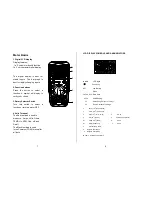
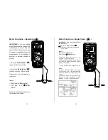
Push–button Functions
Mode Button
Press
the
mode
pushbutton
to
select
the following functions;
DC/AC Voltage, DC/AC Current
Resistance, Diode, Continuity &
Capacitance
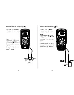
Manual Range & Stroke 4/2(DIS),
Hz, %, ms +, CYL Button
Press to this button to select;
STROKE 4, 2DIS, Hz ,
%
, ms+ ,
CYL
range & V/A/ Resistance
manual Range
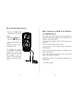
Manual Ranging
The meter turns on in the autoranging mode.
Press the Range button to go to manual ranging.
The display icon "
" will appear. Each press of the range
button will step to the next range as indicated by the units and
decimal point location. Press and hold the Range button for two
seconds to return to autoranging.
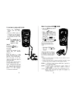
Data Hold
The Data Hold function allows the
meter to "freeze" a measurement for
later reference.
1. Press the DATA HOLD button to
“freeze” the reading on the indicator.
The indication of “HOLD” will appear
in the display.
2. Press the DATA HOLD button
again to return to normal operation.
Peak Hold
The Peak Hold function captures
the peak AC or DC voltage or current.
The meter can capture negative
or positive peaks as fast as
1 millisecond in duration.
1. Set the function switch to the Amps or Volts.
2. Press and Hold the
PEAK
button until “
CAL
” appears
in the display. This procedure will zero the range
selected & the meter will go into manual ranging mode.
3. Press
the
PEAK
button,
Pmax
will display.
4. The display will update each time a higher positive
peak occurs.
5. Press the
PEAK
button again,
Pmin
will display. The
display will now update and indicate the lowest
negative peak.
6. To return to normal operation, press and hold the
PEAK
button until the
Pmin
or
Pmax
indicator
switches off.
Note
: If the Function switch position is changed after a
calibration the Peak Hold calibration must be repeated for the
new function selected.