background image

EN 6

CONVERSION INSTRUCTIONS

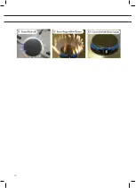
1.  Replace simmer adjustment screw ‘h’ in the gas tap.

Use a 4 mm flat-head screwdriver and, if necessary, pliers to 
remove the simmer adjustment screw (see Figure C2 at the back of 
these instructions) and then fit and tighten the new screw.

2.  Replace the wok burner’s inner burner injector (H2) using a 7 mm 

open-ended spanner. 

Note! 

The inner burner's injector is the top injector in the burner 

body (see Figure C1 at the back of these instructions).

Leak test and performance check (D)

When the appliance is connected to the gas supply: carry out the 
leak test using the leak-test spray.

1.  Seal the injector.
2.  Open the gas tap. 

Note: 

taps fitted with a thermal safeguard must be pressed in, turned 

open and kept pressed in!

3.  Spray the leak-test spray on the connections and inspect for leaks.
4.  Repeat for each burner.

When the appliance is not connected to the gas supply: carry out 
the leak test under pressure using an air pump.

1.  Connect the pump to the gas pipe and close all gas taps.
2.  Increase the pressure to 150 mbar and close the valve between the 

pump and pressure gauge. Check the pressure. The pressure may 
not fall by more than 5 mbar a minute. After the test, open the valve 
between the pump and pressure gauge. 

Note: 

taps fitted with a thermal safeguard must be pressed in, turned 

open and kept pressed in!

3.  Increase the pressure to 150 mbar and once again close the valve 

between the pump and pressure gauge. Check the pressure. The 
pressure may not fall by more than 5 mbar a minute.

4.  Repeat this test for all taps and injectors.

Summary of Contents for HG6411WEBA/A01

Page 1: ...Ombouwvoorschrift Plaatsen service kit wok brander Consigne de conversion Installation du kit de service pour br leur wok Conversion instructions Installation of wok burner service kit...

Page 2: ...NL 7 FR Consigne de conversion FR 3 FR 7 EN Conversion instruction EN 3 EN 7 RU RU 3 RU 7 Gebruikte pictogrammen Pictogrammes utilis s Pictograms used Belangrijk om te weten Important savoir Importan...

Page 3: ...NL 3 INHOUD Inleiding A 4 Demonteren B 5 Ombouwen C 5 Controleren op gasdichtheid en werking D 6 Afmonteren 7 In gebruik stellen 7 Werking controleren E 7...

Page 4: ...n gekeurd op geschiktheid en veiligheid tijdens de typekeuring van het toestel Regelmatig uitgevoerde partijkeuringen garanderen de kwaliteit van originele onderdelen De leverancier adviseert het plaa...

Page 5: ...k en de wokbranderkop weg afb B4 3 Draai de schroeven van de bevestigingsbeugels aan de onderkant van het toestel los zie afbeelding B1 achterin deze instructie 4 Verwijder de schroeven rond de brande...

Page 6: ...een thermische beveiliging indrukken opendraaien en ingedrukt houden 3 Spuit lek testspray op de verbindingen en controleer deze op gasdichtheid 4 Herhaal dit voor elke brander Als het toestel niet i...

Page 7: ...aan In gebruik stellen 1 Plaats de nieuw geleverde wokbrander delen Plaats de knoppen en overige branderdelen 2 Controleer of het toestel is aangesloten op de juiste gassoort en gasdruk 3 Open de gast...

Page 8: ...NL 8...

Page 9: ...FR 3 SOMMAIRE Introduction A 4 D montage B 5 Conversion C 5 Contr le de l tanch it au gaz et du fonctionnement D 6 Montage final 7 Mise en service 7 Contr le du fonctionnement E 7...

Page 10: ...es au cours de l examen de type de l appareil Des contr les par lot ex cut s r guli rement garantissent la qualit des pi ces d origine Le fournisseur recommande de confier l installation de ce kit un...

Page 11: ...commande la verticale 2 Jetez la couronne et le chapeau de br leur wok ill B4 3 D vissez les supports de montage en dessous de l appareil voir l illustration B1 la fin de cette notice 4 Retirez les vi...

Page 12: ...ecteur 2 Ouvrez le robinet de gaz Attention avec des robinets protection thermique il faut enfoncer tourner pour ouvrir et maintenir enfonc 3 Projetez de l a rosol pour fuites sur les raccords et v ri...

Page 13: ...uvelles rondelles en fibre pour les plans profonds maill s 4 Vissez les supports de montage sur le dessous de l appareil Mise en service 1 Placez les nouveaux l ments de br leur wok Placez les boutons...

Page 14: ...FR 8...

Page 15: ...EN 3 CONTENTS Introduction A 4 Disassembly B 5 Conversion C 5 Leak test and performance check D 6 Reassembly 7 Preparations for use 7 Performance check E 7...

Page 16: ...roval testing of the appliance to verify that the parts are suitable for the purpose and are safe Regular inspections of batches are carried out to assure the quality of original parts The supplier re...

Page 17: ...er distributor and wok burner heads Figure B4 3 Loosen the screws of the mounting brackets under the appliance see Figure B1 at the back of these instructions 4 Remove the screws around the burners se...

Page 18: ...safeguard must be pressed in turned open and kept pressed in 3 Spray the leak test spray on the connections and inspect for leaks 4 Repeat for each burner When the appliance is not connected to the ga...

Page 19: ...k burner parts Fit the knobs and other burner parts 2 Check to verify that the appliance is connected to the correct type of gas and gas pressure 3 Open the tap in the gas supply and put the plug in t...

Page 20: ...EN 8...

Page 21: ...RU 3 A 4 B 5 C 5 D 6 7 7 E 7...

Page 22: ...RU 4 A Supervario A B C Torx D E F G 7 4 T20 P2 7...

Page 23: ...RU 5 1 B 1 2 B4 3 4 2 5 3 6 C G20 20 G25 G25 3 25 1 H2 h...

Page 24: ...RU 6 1 h 4 2 2 H2 7 C1 D 1 2 3 4 1 2 150 5...

Page 25: ...RU 7 3 150 5 4 1 2 3 4 1 2 3 E 1 2 E1 E2 E3...

Page 26: ...8 A1 B2 B4 B1 B3...

Page 27: ...9 C1 C2 Table 1 Gas P H2 h G20 20 mbar 0 60 0 45 G25 G25 3 25 mbar 0 60 0 45 G20 10 mbar G20 13 mbar G30 G31 30 37 mbar Natural gas 1 0 kPa ULPG 2 75 kPa...

Page 28: ...10...

Page 29: ...11...

Page 30: ...12...

Page 31: ...13...

Page 32: ...710637 VER 1 29 03 2018...

Reviews: