background image

17

ASSEMBLY

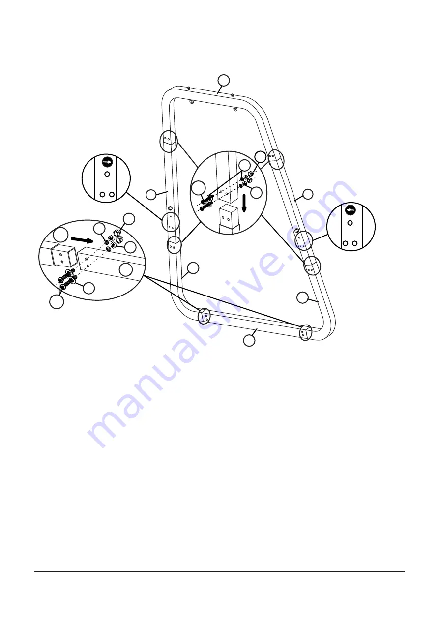
Step 1

Assemble steel floor bar (A), steel corner connector (B), upper U-connector (D) as well as left (C1) and 

right (C2) wooden bar. Pay attention to the direction arrows.

Use the screws (M), spacers (P), nuts (Q) and screw caps (R) for assembly.

B

B

A

B

D

C1

C2

A

M

M

P

P

P

Q

Q

R

R

Summary of Contents for RedNeck GHS1

Page 1: ...1 GHS1 VERSION L BS ...

Page 2: ...INHALTSVERZEICHNIS GEWÄHRLEISTUNGSBESTIMMUNGEN 3 TEILELISTE 4 ZUSAMMENBAU 6 GEWÄHRLEISTUNGSRECHT 12 TABLE OF CONTENT WARRANTY TERMS 13 PARTLIST 14 ASSEMBLY 16 WARRANTY DEVICE 22 ...

Page 3: ...r an Ihren Händler oder direkt an uns Unsere Serviceadresse https www asviva de kontakt Damit Ihnen unsere Service Mitarbeiter optimal weiterhelfen können beachten Sie bitte folgende Vorgehensweise 1 Ist ein bestimmtes Teil beschädigt Teilen Sie uns bitte anhand der Teileiste die genaue Teilenummer mit 2 Liegt eine Störung beim Gerät vor Sollten Sie die Möglichkeit einer Videoaufnahme z B Handykam...

Page 4: ... C2 1 C1 J 1 H 2 G 8 I 2 Nr Nr A 1 F 1 Menge Menge Illustration Illustration V W 4 2 8 U 2 T 1 Q R 22 S 1 M8 K2 K1 L P 24 4 8 32 O 2 N 4 M 12 M6X35 M6X45 M8X80 M8X60 M8X110 M8X115 M8X16 22 Nr Illustration Menge Nr Illustration Menge M6 X ...

Page 5: ...erer U Stecker P Abstandshalter M8 E1 linkes Bein Q Mutter M8 E2 rechtes Bein R Schraubenkappe F vorderer U Stecker S Schraubenschlüssel G Sitzlatte T Inbusschlüssel M8 H Armlehne U Inbusschlüssel M6 I Hängeseil V Dreieck Abstandhalter J Kissen W Dämpfer für Karabiner e Armlehnenkissen X Mutter M6 für K1 K2 K1 Schraube M6 35 K2 Schraube M6 45 TEILELISTE I G H H I J E1 E2 A B B F D C1 C2 e ...

Page 6: ...hrauben und ziehen diese anschließend vorsichtig an Bitte montieren Sie die Möbelstücke auf ebenem Grund und achten Sie dabei darauf dass die Möbelstücke perfekt zentriert montiert werden damit wackeln verhindert werden kann Was man nicht tun sollte Verwenden Sie die Möbel nicht wenn Teile fehlen beschädigt oder abgenutzt sind Verwenden Sie keine Elektrischen Werkzeuge für den Aufbau da diese die ...

Page 7: ...ckverbinder B Oberen U Anschluss D sowie linke C1 und rechte C2 Holzstange zusammen Achten Sie dabei auf die Richtungspfeile Verwenden Sie für den Zusammenbau die die Schrauben M Abstandhalter P Mutter Q und Schraubenkappen R B B A B D C1 C2 A M M P P P Q Q R R ...

Page 8: ...hluss F mit den linken E1 und rechten E2 Beinen zusammen Verbinden Sie anschließend das Gestell mit dem Hauptrahmen mittels den mitgelieferten Dreieck Abstandhaltern V Schrauben N Muttern Q und Schraubenkappen R ZUSAMMENBAU F E L N O V Q Q R R P Step2 ...

Page 9: ...ntieren Sie die einzelnen Sitzlatten G an den Armlehnen H Hierfür verwenden Sie die im Lieferumfang enthaltenen Schrauben K2 und Muttern X Hängen Sie die Seile I wie abgebildet an die Armlehnen ein G H H I I I H K2 G H X K1 G H ...

Page 10: ...10 ZUSAMMENBAU Schritt 4 Hängen Sie das Sitzgerüst an den Hängeseilen I und unter Verwendung der Dämpfer W am Hauptrahmen auf I D D W ...

Page 11: ...11 ZUSAMMENBAU Schritt 5 Binden Sie die Armlehnenkissen e an den Armlehnen H fest und legen Sie das Kissen J auf e H e e J Step5 ...

Page 12: ...ssbrauch entstanden ist 1 Die Gewährleistung bezieht sich nicht auf alle Teile die einem funktionsbedingten Verschleiß unterliegen soweit es sich nicht um Produktions oder Materialfehler handelt Schäden die durch unsachgemäße oder mangelhafte Pflege und nicht fachmännisch durchgeführ te Reparaturen Umbauten oder Austausch von Teilen entstehen Schäden die durch unsachgemäßen Gebrauch und höhere Gew...

Page 13: ... invoice number Our service is available 24 hours Our service adress https www asviva de contact To ensure that our service staff can help you optimally please consider the following procedure 1 Is a specific part damaged Please tell us the exact part number using the parts list 2 Is there a fault with the unit Should you have the possibility of a video recording e g mobile phone camera pickup the...

Page 14: ... B 2 1 D 1 C2 1 C1 J 1 H 2 G 8 I 2 No No A 1 F 1 Quant Quant Picture Picture V W 4 2 8 U 2 T 1 Q R 22 S 1 M8 K2 K1 L P 24 4 8 32 O 2 N 4 M 12 M6X35 M6X45 M8X80 M8X60 M8X110 M8X115 M8X16 22 No Picture Quant No Picture Quant X M6 ...

Page 15: ...2 right wooden bar O screw M8 115 D top U connector P spacer M8 E1 left leg Q nut M8 E2 right leg R screw cap F front U conector S wrench G seat slat T Allen M8 H armrest U Allen M6 I hanging rope V traiangle spacer J cushion W silencor for carabiner e armrest cushion X nut M6 for K1 K2 K1 screw M6 35 K2 screw M6 45 I G H H I J E1 E2 A B B F D C1 C2 e ...

Page 16: ...k the screws beforehand and then tighten them careful ly Please mount the pieces of furniture on level ground and make sure that the pieces of furniture are perfectly centered so that wobbling can be prevented What not to do Do not use the furniture if parts are missing damaged or worn Do not use electrical tools for the assembly as these can damage the furniture Do not overtighten the screws Do n...

Page 17: ...loor bar A steel corner connector B upper U connector D as well as left C1 and right C2 wooden bar Pay attention to the direction arrows Use the screws M spacers P nuts Q and screw caps R for assembly B B A B D C1 C2 A M M P P P Q Q R R ...

Page 18: ... assemble the front U connector F with the left E1 and right E2 legs Then connect the frame to the main frame using the supplied triangle spacers V screws N nuts Q and screw caps R F E L N O V Q Q R R P Step2 ASSEMBLY ...

Page 19: ...p 3 Mount the individual seat slats G on the armrests H Use the screws K2 and nuts X included in the scope of delivery for this Hang the ropes I on the armrests as shown G H H I I I H K2 G H X K1 G H ASSEMBLY ...

Page 20: ...20 Step 4 Hang the scaffold on the hanging cables I and using the dampers W on the main frame I D D W ASSEMBLY ...

Page 21: ...21 Step 5 Tie the armrest cushions e to the armrests H and put the cushion J on e H e e J Step5 ASSEMBLY ...

Page 22: ...nt at the time of handing over and was not caused by improper use function related wear or abuse 1 The warranty does not cover all parts of the device which are subject to wear due to function in so far as they are not production or material defects Damage caused by improper or faulty maintenance and repairs alterations or replacement of parts which have not been carried out by a qualified person ...

Reviews: