background image

DO NOT overtighten the screws! Doing so can damage the motherboard.

2.2.3 

Placement direction

When installing the motherboard, ensure that you place it into the chassis in 
the correct orientation. The edge with external ports goes to the rear part of the 
chassis as indicated in the image below.
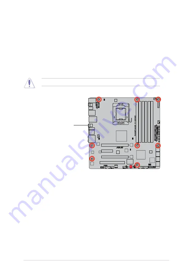
2.2.4 

Screw holes

Place eight (8) screws into the holes indicated by circles to secure the motherboard 
to the chassis.

Place this side towards 

the rear of the chassis

ROG Rampage III GENE

2-9

Summary of Contents for Rampage III GENE

Page 1: ...Motherboard Rampage III GENE ...

Page 2: ...CHANTABILITY OR FITNESS FOR A PARTICULAR PURPOSE IN NO EVENT SHALL ASUS ITS DIRECTORS OFFICERS EMPLOYEES OR AGENTS BE LIABLE FOR ANY INDIRECT SPECIAL INCIDENTAL OR CONSEQUENTIAL DAMAGES INCLUDING DAMAGES FOR LOSS OF PROFITS LOSS OF BUSINESS LOSS OF USE OR DATA INTERRUPTION OF BUSINESS AND THE LIKE EVEN IF ASUS HAS BEEN ADVISED OF THE POSSIBILITY OF SUCH DAMAGES ARISING FROM ANY DEFECT OR ERROR IN ...

Page 3: ...ou proceed 2 1 2 2 Motherboard overview 2 7 2 2 1 Motherboard layout 2 7 2 2 2 Layout contents 2 8 2 2 3 Placement direction 2 9 2 2 4 Screw holes 2 9 2 3 Central Processing Unit CPU 2 10 2 3 1 Installing the CPU 2 10 2 3 2 Installing the CPU heatsink and fan 2 13 2 3 3 Uninstalling the CPU heatsink and fan 2 14 2 4 System memory 2 15 2 4 1 Overview 2 15 2 4 2 Memory configurations 2 16 2 4 3 Inst...

Page 4: ...tch 2 47 Chapter 3 BIOS setup 3 1 Managing and updating your BIOS 3 1 3 1 1 ASUS Update utility 3 1 3 1 2 ASUS EZ Flash 2 utility 3 4 3 1 3 ASUS CrashFree BIOS 3 utility 3 5 3 2 BIOS setup program 3 6 3 2 1 BIOS menu screen 3 7 3 2 2 Menu bar 3 7 3 2 3 Navigation keys 3 7 3 2 4 Menu items 3 8 3 2 5 Submenu items 3 8 3 2 6 Configuration fields 3 8 3 2 7 Pop up window 3 8 3 2 8 Scroll bar 3 8 3 2 9 ...

Page 5: ... 14 3 3 19 QPI Voltage OCP Enabled 3 14 3 3 20 Extreme OV Disabled 3 14 3 3 21 CPU Voltage Control Absolute VID 3 15 3 3 22 CPU Voltage Auto 3 15 3 3 23 CPU PLL Voltage Auto 3 15 3 3 24 QPI DRAM Core Voltage Auto 3 15 3 3 25 IOH Voltage Auto 3 15 3 3 26 IOH PCIE Voltage Auto 3 15 3 3 27 ICH Voltage Auto 3 15 3 3 28 ICH PCIE Voltage Auto 3 15 3 3 29 DRAM Bus Voltage Auto 3 16 3 3 30 DRAM REF Voltag...

Page 6: ...2 Repost Video on S3 Resume No 3 34 3 6 3 ACPI 2 0 Support Disabled 3 34 3 6 4 ACPI APIC Support Enabled 3 35 3 6 5 EuP Ready Disabled 3 35 3 6 6 APM Configuration 3 35 3 6 7 Hardware Monitor 3 37 3 7 Boot menu 3 40 3 7 1 Boot Device Priority 3 40 3 7 2 Boot Settings Configuration 3 41 3 7 3 Security 3 42 3 8 Tools menu 3 44 3 8 1 ASUS EZ Flash 2 3 44 3 8 2 ASUS O C Profile 3 45 3 8 3 GO_Button Fi...

Page 7: ...he RAID item in BIOS 4 19 4 4 4 Intel Matrix Storage Manager option ROM utility 4 20 4 5 Creating a RAID driver disk 4 25 4 5 1 Creating a RAID driver disk without entering the OS 4 25 4 5 2 Creating a RAID driver disk in Windows 4 25 Chapter 5 Multiple GPU technology support 5 1 ATI CrossFireX technology 5 1 5 1 1 Requirements 5 1 5 1 2 Before you begin 5 1 5 1 3 Installing CrossFireX graphics ca...

Page 8: ...d on the user is encouraged to try to correct the interference by one or more of the following measures Reorient or relocate the receiving antenna Increase the separation between the equipment and receiver Connect the equipment to an outlet on a circuit different from that to which the receiver is connected Consult the dealer or an experienced radio TV technician for help Canadian Department of Co...

Page 9: ...fore installing the motherboard and adding devices on it carefully read all the manuals that came with the package Before using the product ensure all cables are correctly connected and the power cables are not damaged If you detect any damage contact your dealer immediately To avoid short circuits keep paper clips screws and staples away from connectors slots sockets and circuitry Avoid dust humi...

Page 10: ...r 1 Product introduction This chapter describes the features of the motherboard and the new technology it supports Chapter 2 Hardware information This chapter lists the hardware setup procedures that you have to perform when installing system components It includes description of the switches jumpers and connectors on the motherboard Chapter 3 BIOS setup This chapter tells how to change system set...

Page 11: ...mbols used throughout this manual Typography Bold text Indicates a menu or an item to select Italics Used to emphasize a word or a phrase Key Keys enclosed in the less than and greater than sign means that you must press the enclosed key Example Enter means that you must press the Enter or Return key Key1 Key2 Key3 If you must press two or more keys simultaneously the key names are linked with a p...

Page 12: ...al x16 mode 1 x PCIe x4 1 x PCI 2 2 Multi GPU Technology Support NVIDIA SLI ATI CrossFireX Technology Storage ICH10R Southbridge 6 x SATA 3 0 Gb s ports gray Intel Matrix Storage Technology supports RAID 0 1 5 and 10 Marvell PCIe 9128 SATA 6Gb s controller 2 x SATA 6 0 Gb s ports red LAN Intel Gigabit LAN High Definition Audio SupremeFX X Fi 2 built in 8 channel High Definition Audio CODEC EAX Adv...

Page 13: ...ecall Other Special Features ASUS MyLogo3 ASUS Fan Xpert ASUS EZ Flash 2 ASUS CrashFree BIOS 3 ASUS Q Connector ASUS Q Slot ASUS Q DIMM BIOS Features 16Mb AMI BIOS PnP DMI2 0 WfM2 0 SM BIOS 2 5 ACPI2 0a Multi Language BIOS Manageability WOL by PME WOR by PME PXE Back Panel I O Ports 1 x PS 2 Keyboard port purple 1 x Clr CMOS switch 1 x Optical S PDIF out port 1 x IEEE 1394a connector 1 x LAN RJ45 ...

Page 14: ...tor 1 x 24 pin ATX Power connector 1 x 8 pin ATX 12V Power connectors 1 x En Dis able Clr CMOS header 1 x En Dis able QPI_LL header 1 x START Power On button 1 x RESET button 1 x Front panel audio connector 1 x System panel connector Software Support DVD Drivers and Applications Sound Blaster X Fi MB2 Utility Kaspersky Anti Virus ROG GameFirst Utility ASUS AI Suite II ASUS PC Probe II ASUS Update ...

Page 15: ...1 Chapter 1 Product introduction This chapter describes the motherboard features and the new technologies it supports ...

Page 16: ...ROG Rampage III GENE Chapter summary 1 1 1 Welcome 1 1 1 2 Package contents 1 1 1 3 Special features 1 2 ...

Page 17: ...he items in your package with the list below If any of the above items is damaged or missing contact your retailer 1 2 Package contents Check your motherboard package for the following items Motherboard ROG Rampage III GENE Cables 1 x SLI Cable 3 x 2 in 1 SATA signal cables 1 x 2 in 1 SATA 6G cables Accessories 1 x ROG Connect cable 1 x 2 in 1 ASUS Q Connector Kit 1 x I O Shield 1 x Cable Ties Pac...

Page 18: ...ntel Core i7 processors in LGA1366 package with integrated memory controller to support 3 channel 6 DIMMs DDR3 memory Supports Intel QuickPath Interconnect QPI with a system bus of up to 6 4 GT s and a max bandwidth of up to 25 6 GB s Intel Core i7 processor is one of the most powerful and energy efficient CPUs in the world Intel X58 Chipset The Intel X58 Express Chipset is one of the most powerfu...

Page 19: ...lowing you to view real time POST code and hardware status readouts on your notebook as well as make on the fly parameter adjustments at a purely hardware level Diagram power reset button flash BIOS through notebook Refer to page 2 32 for details MemOK Any memory is A OK Memory compatibility is among the top concerns when it comes to computer upgrades Worry no more MemOK is the fastest memory boot...

Page 20: ...ing shop Extreme Tweakers is the one stop shop to fine tune your system to optimal performance No matter if you re looking for frequency adjustment over voltage options or memory timing settings they re all here Voltiminder LED Friendly reminder on Voltage Settings In the pursuit of extreme performance overvoltage adjustment is critical but risky Acting as the red zone of a tachometer the Voltimin...

Page 21: ...he Q Connector allows you to connect or disconnect chassis front panel cables in one easy step with one complete module This unique adapter eliminates the trouble of plugging in one cable at a time making connection quick and accurate 1 3 4 ASUS special features USB 3 0 Support 10X Faster Date Rates Experience ultra fast data transfers at 4 8Gbps with USB 3 0 the latest connectivity standard Built...

Page 22: ...io High Definition Audio previously code named Azalia CODEC enables high quality 192KHz 24 bit audio output jack sensing feature retasking functions and multi streaming technology that simultaneously sends different audio streams to different destinations This motherboard now adopts the future standard to deliver the most vivid audio enjoyment Kaspersky Anti Virus The best protection from viruses ...

Page 23: ...ter 2 Hardware information This chapter lists the hardware setup procedures that you have to perform when installing system components It includes description of the jumpers and connectors on the motherboard ...

Page 24: ...efore you proceed 2 1 2 2 Motherboard overview 2 7 2 3 Central Processing Unit CPU 2 10 2 4 System memory 2 15 2 5 Expansion slots 2 23 2 6 Jumper 2 27 2 7 Connectors 2 29 2 8 Starting up for the first time 2 46 2 9 Turning off the computer 2 47 ...

Page 25: ...ase before handling components to avoid damaging them due to static electricity Hold components by the edges to avoid touching the ICs on them Whenever you uninstall any component place it on a grounded antistatic pad or in the bag that came with the component Before you install or remove any component ensure that the ATX power supply is switched off or the power cord is detached from the power su...

Page 26: ...ent refer to 3 3 Extreme Tweaker menu 1 CPU LED The CPU LED has three voltage displays Vcore voltage CPU PLL 1 8 voltage and QPI DRAM Core voltage you can select the voltage to display in BIOS Refer to the illustration below for the location of the CPU LED and the table below for LED definition Normal green High yellow Crazy red VCore 0 85 1 5 1 50625 1 59375 1 6 CPU PLL 1 8V 1 20375 1 89475 1 908...

Page 27: ...he SB 1 5 Voltage You can select the voltage to display in BIOS Refer to the illustration below for the location of the northbridge southbridge LEDs and the table below for LED definition Normal green High yellow Crazy red NB 1 1 Voltage 1 113 1 391 1 4045 1 643 1 65625 NB 1 5 Voltage 1 5105 1 696 1 709 1 84175 1 855 SB 1 1 Voltage 1 113 1 591 1 60325 1 84175 1 855 SB 1 5 Voltage 1 5105 1 6165 1 6...

Page 28: ...D does not light up when there is no hard disk drive connected to the motherboard or when the hard disk drive does not function 3 Memory LED Refer to the illustration below for the location of the memory LED and the table below for LED definition Normal green High yellow Crazy red DDR3 1 5V 1 20575 1 60325 1 6165 1 802 1 81525 2 4 Chapter 2 Hardware information ...

Page 29: ...oard component The illustration below shows the location of the onboard power on switch When you turn on the ATX power supply the Power LED flashes three times to indicate that the system is ready to boot Wait till the flash stops before you press the power on switch 6 GO LED Blinking Indicates that MemOK is enabled before POST Lighting Indicates that the system loads the preset profile GO_Button ...

Page 30: ...s in sequence during motherboard booting process If an error is found the corresponding LED will continue lighting until the problem is solved This user friendly design provides an intuitional way to locate the root problem within a second 2 6 Chapter 2 Hardware information ...

Page 31: ...2 2 Motherboard overview 2 2 1 Motherboard layout ROG Rampage III GENE 2 7 ...

Page 32: ...vell Serial ATA 6 0 Gb s connectors 7 pin SATA6G_1 2 red 2 34 6 ICH10R Serial ATA connectors 7 pin SATA1 6 grey 2 33 7 System panel connector 20 8 pin PANEL 2 41 8 QPI_LL 3 pin QPI_LL_SW 2 28 9 Clear RTC RAM 3 pin CLRTC_SW 2 27 10 USB connectors 10 1 pin USB78 USB910 2 35 11 Reset switch 2 43 12 Power on switch 2 43 13 GO button 2 44 14 IEEE 1394a port connector 10 1 pin IE1394_2 2 36 15 Front pan...

Page 33: ... place it into the chassis in the correct orientation The edge with external ports goes to the rear part of the chassis as indicated in the image below 2 2 4 Screw holes Place eight 8 screws into the holes indicated by circles to secure the motherboard to the chassis Place this side towards the rear of the chassis ROG Rampage III GENE 2 9 ...

Page 34: ...will process Return Merchandise Authorization RMA requests only if the motherboard comes with the cap on the LGA1366 socket The product warranty does not cover damage to the socket contacts resulting from incorrect CPU installation removal or misplacement loss incorrect removal of the PnP cap Ensure that all power cables are unplugged before installing the CPU 2 3 1 Installing the CPU To install a...

Page 35: ...oad lever in the direction of the arrow to a 135º angle 4 Lift the load plate with your thumb and forefinger to a 100º angle Load plate 4 3 5 Remove the PnP cap from the CPU socket PnP cap ROG Rampage III GENE 2 11 ...

Page 36: ...PU that the heatsink will be in contact with ensuring that it is spread in an even thin layer Some heatsinks come with pre applied Thermal Interface Material If so skip this step Gold triangle mark Alignment key CPU notch The Thermal Interface Material is toxic DO NOT eat the Thermal Interface Material If it gets into your eyes or touches your skin ensure that you wash it off immediately and seek ...

Page 37: ...ith the LGA775 and LGA1366 sockets in size and dimension Orient the heatsink and fan assembly such that the CPU fan cable is closest to the CPU fan connector If you purchased a separate CPU heatsink and fan assembly ensure that the Thermal Interface Material is properly applied to the CPU heatsink or CPU before you install the heatsink and fan assembly Ensure that you have installed the motherboar...

Page 38: ...ng the CPU heatsink and fan To uninstall the CPU heatsink and fan 1 Disconnect the CPU fan cable from the connector on the motherboard 2 Rotate each fastener counterclockwise 3 Pull up two fasteners at a time in a diagonal sequence to disengage the heatsink and fan assembly from the motherboard A A B B A A B B 4 Carefully remove the heatsink and fan assembly from the motherboard 2 14 Chapter 2 Har...

Page 39: ...s DIMM sockets A DDR3 module has the same physical dimensions as a DDR2 DIMM but is notched differently to prevent installation on a DDR2 DIMM socket DDR3 modules are developed for better performance with less power consumption The figure illustrates the location of the DDR3 DIMM sockets ROG Rampage III GENE 2 15 ...

Page 40: ... single channel operation Due to Intel spec definition X M P DIMMs and DDR3 1600 are supported for one DIMM per channel only According to Intel CPU spec DIMMs with voltage requirement over 1 65V may damage the CPU permanently We recommend you install the DIMMs with the voltage requirement below 1 65V Always install DIMMs with the same CAS latency For optimum compatibility we recommend that you obt...

Page 41: ... 6GB 3 x 2GB DS 9 9 9 1 65 OCZ OCZ3RPR1866C9LV6GK 6GB 3 x 2GB DS 9 9 9 1 65 Super Talent W1866UX2G8 XMP 2GB 2 x 1GB SS 8 8 8 24 Patriot PVS32G1866LLK XMP 2GB 2 x 1GB SS 8 8 8 24 1 9 Rampage III GENE Motherboard Qualified Vendors Lists QVL DDR 3 1800MHz capability Vendor Part No Size SS DS Timing Voltage DIMM socket support Optional 2 DIMM 3 DIMM 4 DIMM 6 DIMM G SKILL F3 14400CL9D 4GBRL XMP 4GB 2 x...

Page 42: ...RM XMP 4GB 2 x 2GB DS 8 8 8 24 1 6 G SKILL F3 12800CL9D 4GBECO XMP 4GB 2 x 2GB DS 9 9 9 24 1 35 G SKILL F3 12800CL8T 6GBPI XMP 6GB 3 x 2GB DS 8 8 8 21 1 6 1 65 G SKILL F3 12800CL9T 6GBNQ 6GB 3 x 2GB DS 9 9 9 24 1 5 1 6 KINGMAX FLGD45F B8MF7 XMP 1GB SS KINGSTON KHX1600C9D3K3 12GX XMP 12GB 3 x 4GB DS 1 65 KINGSTON KHX1600C9D3K3 12GX XMP 12GB 3 x 4GB DS 9 1 65 KINGSTON KHX1600C9D3K6 24GX XMP 24GB 6x ...

Page 43: ...ILL F3 10666CL8D 4GBECO XMP 4GB 2 x 2GB DS 8 8 8 24 1 35 G SKILL F3 10666CL8D 4GBHK XMP 4GB 2 x 2GB DS 8 8 8 21 1 5 1 6 G SKILL F3 10666CL8D 4GBRM XMP 4GB 2 x 2GB DS 8 8 8 21 1 5 1 6 G SKILL F3 10666CL9T 6GBNQ 6GB 3 x 2GB DS 9 9 9 24 1 5 GEIL GB34GB1333C7DC 4GB 2 x 2GB DS GEIL GL1L128M88BA15FW 7 7 7 24 1 5 GEIL GG34GB1333C9DC 4GB 2 x 2GB DS GEIL GL1L128M88BA12N 9 9 9 24 1 3 GEIL GV34GB1333C7DC 4GB...

Page 44: ...Asint SLY3128M8 EDJ 1GB SS Asint DDRIII1208 DJ Asint SLY3128M8 EDJE 1GB SS ELPIDA J1108BASE DJ E Asint SLZ3128M8 EDJ 2GB DS Asint DDRIII1208 DJ Asint SLZ3128M8 EDJE 2GB DS ELPIDA J1108BASE DJ E ASUS N A 1GB DS ATP AQ28M64A8BJH9S 1GB SS SAMSUNG K4B1G0846E ATP AQ28M72D8BJH9S 1GB SS SAMSUNG K4B1G0846D ECC ATP AQ56M64B8BJH9S 2GB DS SAMSUNG K4B1G0846D ATP AQ56M72E8BJH9S 2GB DS SAMSUNG K4B1G0846D ECC BU...

Page 45: ...Y5TQ1G831ZNFP G7 7 KINGSTON KVR1066D3N7 1G 1GB SS KINGSTON D1288JEKAPA7U 7 1 5 KINGSTON KVR1066D3N7 2G 2GB DS KINGSTON D1288JEKAPGA7U 7 1 5 KINGSTON KVR1066D3N7 2G 2GB DS ELPIDA J1108BABG DJ E 1 5 KINGSTON KVR1066D3N7 4G 4GB DS SAMSUNG K4B2G0846B HCF8 1 5 MICRON MT8JTF12864AZ 1G1F1 1GB SS MICRON 8ZF22 D9KPV 7 MICRON MT8JTF12864AZ 1G1F1 1GB SS MICRON D9KPT 7 MICRON MT9JSF12872AZ 1G1F1 1GB SS MICRON...

Page 46: ...ining clip outward 2 Align a DIMM on the socket such that the notch on the DIMM matches the DIMM slot key on the socket A DIMM is keyed with a notch so that it fits in only one direction DO NOT force a DIMM into a socket in the wrong direction to avoid damaging the DIMM Ensure to unplug the power supply before adding or removing DIMMs or other system components Failure to do so may cause severe da...

Page 47: ... with the screw you removed earlier 6 Replace the system cover 2 5 2 Configuring an expansion card After installing the expansion card configure it by adjusting the software settings 1 Turn on the system and change the necessary BIOS settings if any See Chapter 3 for information on BIOS setup 2 Assign an IRQ to the card Refer to the tables on the next page 3 Install the software drivers for the ex...

Page 48: ...der for PCI Steering 12 7 Reserved 13 8 Numeric Data Processor 14 9 Primary IDE Channel ICH A B C D E F G H PCIE1_1 shared Intel 82657V shared PCI_1 shared USB controller 1 shared USB controller 2 shared USB controller 3 shared USB controller 4 shared USB controller 5 shared USB controller 6 shared USB 2 0 controller 1 shared USB 2 0 controller 2 shared SATA controller 1 shared SATA controller 2 s...

Page 49: ...ards and other cards that comply with the PCI Express specifications Install a PCIe x4 device to a PCIe x4 slot prior to a PCIe x16 slot 2 5 6 PCI Express 2 0 x16 slots This motherboard has two PCI Express 2 0 x16 slots that support PCI Express x16 2 0 graphic cards complying with the PCI Express specifications Refer to the figure below for the location of the slots PCI Express 2 0 x16_1 slot PCI ...

Page 50: ... 0 x16_2 slots for PCI Express x16 graphics cards to get better performance We recommend that you provide sufficient power when running CrossFireX mode See page 2 40 for details Connect a chassis fan to the motherboard connector labeled CHA_FAN1 2 when using multiple graphics cards for better thermal environment See page 2 38 for details 2 26 Chapter 2 Hardware information ...

Page 51: ...without 5VSB power AC power loss S5 Power off with 5VSB power The system shuts dowm immediately The clr CMOS switch will not function if the CLRTC_SW jumper is moved to the Disable position but the shutdwon function in S0 mode DOS mode still works Ensure to re enter your previous BIOS settings after you clear the CMOS You do not need to clear the RTC when the system hangs due to CPU overclocking W...

Page 52: ...ents QPI voltage from dropping too much when you perform overclocking The low QPI voltage may cause system malfunction Set the jumper to pin 2 3 to activate this function and pin 1 2 to disable this function 2 28 Chapter 2 Hardware information ...

Page 53: ...nd 2 4 USB 3 0 ports 1 and 2 10 ROG Connect switch 5 USB 2 0 ports 5 and 6 11 ROG Connect port 6 Clear CMOS switch 12 Audio I O ports To use hot plug set the Controller Mode in the BIOS settings to AHCI mode See section 3 5 3 Onboard Devices Configuration for details You cannot boot from USB 3 0 ports blue and remember to install the USB 3 0 driver before using the ports ROG Rampage III GENE 2 29 ...

Page 54: ...nnect to Headphone and Mic Audio 2 4 6 or 8 channel configuration Port Headset 2 channel 4 channel 6 channel 8 channel Light Blue Line In Line In Line In Line In Lime Line Out Front Speaker Out Front Speaker Out Front Speaker Out Pink Mic In Mic In Mic In Mic In Orange Center Subwoofer Center Subwoofer Black Rear Speaker Out Rear Speaker Out Rear Speaker Out Gray Side Speaker Out Speed LED Activit...

Page 55: ...Connect to Stereo Speakers Connect to 2 1 channel Speakers Connect to 4 1 channel Speakers ROG Rampage III GENE 2 31 ...

Page 56: ...Connect to 5 1 channel Speakers Connect to 7 1 channel Speakers 2 32 Chapter 2 Hardware information ...

Page 57: ...ata hard disk drives to these connectors If you intend to create a Serial ATA RAID set using these connectors set the Configure SATA as item in the BIOS to RAID See section 3 4 5 Storage Configuration for details Before creating a RAID set refer to section 4 4 RAID configurations or the manual bundled in the motherboard support DVD You must install Windows XP Service Pack 2 or later versions befor...

Page 58: ...r versions before using Serial ATA hard disk drives Press Ctrl M during POST to enter the Marvell RAID utility to create or delete a RAID configuration If you want to install a Windows operating system to a RAID configuration created using the Marvell SATA controller you have to create a RAID driver disk using the motherboard support DVD and load the driver during OS installation For 32 64bit Wind...

Page 59: ...system chassis These USB connectors comply with USB 2 0 specification that supports up to 480 Mbps connection speed Never connect a 1394 cable to the USB connectors Doing so will damage the motherboard You can connect the USB cable to ASUS Q Connector USB blue first and then install the Q Connector USB to the USB connector onboard The USB cable is purchased separately ROG Rampage III GENE 2 35 ...

Page 60: ...o the IEEE 1394a connector Doing so will damage the motherboard 5 Digital audio connector 4 1 pin SPDIF_OUT This connector is for an additional Sony Philips Digital Interface S PDIF port s Connect the S PDIF Out module cable to this connector then install the module to a slot opening at the back of the system chassis The S PDIF out module is purchased separately The IEEE 1394a cable is purchased s...

Page 61: ...ommend that you connect a high definition front panel audio module to this connector to avail of the motherboard s high definition audio capability If you want to connect a high definition front panel audio module to this connector set the Front Panel Type item in the BIOS setup to HD Audio if you want to connect an AC 97 front panel audio module to this connector set the item to AC97 By default t...

Page 62: ...suring that the black wire of each cable matches the ground pin of the connector DO NOT forget to connect the fan cables to the fan connectors Insufficient air flow inside the system may damage the motherboard components These are not jumpers DO NOT place jumper caps on the fan connectors If you install two VGA cards we recommend that you plug the chassis fan cable to the motherboard connector lab...

Page 63: ...ce the other end to the device which you want to monitor temperature The optional fan can work with the temperature sensor for a better cooling effect Enable OPT FAN overheat protection in BIOS if you connect thermal sensor cable to this connector Refer to page 3 34 for details The thermal sensor cable is purchased separately ROG Rampage III GENE 2 39 ...

Page 64: ...mum power of 600 W Do not forget to connect the 8 pin EATX12V power plugs otherwise the system will not boot Use of a PSU with a higher power output is recommended when configuring a system with more power consuming devices The system may become unstable or may not boot up if the power is inadequate Refer to the Appendix for the certified 500W power supply or above If you are uncertain about the m...

Page 65: ...This 4 pin connector is for the chassis mounted system warning speaker The speaker allows you to hear system beeps and warnings ATX power button soft off button 2 pin PWRSW This connector is for the system power button Pressing the power button turns the system on or puts the system in sleep or soft off mode depending on the BIOS settings Pressing the power switch for more than four seconds while ...

Page 66: ...then match them to their respective front panel cable labels The labels on the front panel cables may vary depending on the chassis model 2 Install the ASUS Q Connector to the system panel connector ensuring the orientation matches the labels on the motherboard 3 The front panel functions are now enabled The figure shows the Q Connector is properly installed on the motherboard IDE_LED POWER SW RES...

Page 67: ...on a bare or open case system This is ideal for overclockers and gamers who continually change settings to enhance system performance 1 Power on switch Press the power on switch to wake power up the system 2 Reset switch Press the reset switch to reboot the system ROG Rampage III GENE 2 43 ...

Page 68: ...3 GO button Press the GO button before POST to enable MemOK or press it to quickly load the preset profile GO_Button file for temporary overclocking when in OS 2 44 Chapter 2 Hardware information ...

Page 69: ... easier access to the measure points when a multitester is employed for more accurate measurements during your busy overclocking work Refer to the following illustration for ProbeIt location Using ProbeIt You may connect the multitester to the motherboard as shown The photos above are for reference only the actual motherboard layout and measure points location may differ by models ROG Rampage III ...

Page 70: ... may light up or switch between orange and green after the system LED turns on The system then runs the power on self tests or POST While the tests are running the BIOS beeps see BIOS beep codes table below or additional messages appear on the screen If you do not see anything within 30 seconds from the time you turned on the power the system may have failed a power on test Check the jumper settin...

Page 71: ...n Off button to shut down the computer 3 The power supply should turn off after Windows shuts down 2 9 2 Using the dual function power switch While the system is ON pressing the power switch for less than four seconds puts the system to sleep mode or to soft off mode depending on the BIOS setting Pressing the power switch for more than four seconds lets the system enter the soft off mode regardles...

Page 72: ...2 48 Chapter 2 Hardware information ...

Page 73: ...3 BIOS setup This chapter tells how to change the system settings through the BIOS Setup menus Detailed descriptions of the BIOS parameters are also provided ...

Page 74: ...age III GENE 3 1 Managing and updating your BIOS 3 1 3 2 BIOS setup program 3 6 3 3 Extreme Tweaker menu 3 9 3 4 Main menu 3 17 3 5 Advanced menu 3 23 3 6 Power menu 3 34 3 7 Boot menu 3 40 3 8 Tools menu 3 44 3 9 Exit menu 3 49 ...

Page 75: ...al motherboard BIOS using the ASUS Update utility Installing ASUS Update To install ASUS Update 1 Place the support DVD in the optical drive The Drivers menu appears 2 Click the Utilities tab then click Install ASUS Update VX XX XX 3 The ASUS Update utility is copied to your system 3 1 1 ASUS Update utility The ASUS Update is a utility that allows you to manage save and update the motherboard BIOS...

Page 76: ...rk traffic or click Auto Select Click Next Updating the BIOS through the Internet To update the BIOS through the Internet 1 Launch the ASUS Update utility from the Windows desktop by clicking Start Programs ASUS ASUSUpdate ASUSUpdate The ASUS Update main window appears 2 Select Update BIOS from the Internet option from the drop down menu then click Next ...

Page 77: ...ile option from the drop down menu then click Next 4 From the FTP site select the BIOS version that you wish to download Click Next 5 Follow the screen instructions to complete the update process The ASUS Update utility is capable of updating itself through the Internet Always update the utility to avail all its features 3 Locate the BIOS file from the Open window then click Open 4 Follow the scre...

Page 78: ... EZ Flash 2 and press Enter to enable it ASUSTek EZ Flash 2 BIOS ROM Utility V4 18 Current ROM Update ROM A Note Enter Select or Load Tab Switch V Drive Info Up Down Home End Move B Backup Esc Exit PATH A BOARD Rampage III GENE VER 0213 H 00 B 12 DATE 06 08 2010 BOARD Unknown VER Unknown DATE Unknown 2 Press Tab to switch between drives until the correct BIOS file is found When found EZ Flash 2 pe...

Page 79: ...m and save it to a USB flash drive Recovering the BIOS To recover the BIOS 1 Turn on the system 2 Insert the motherboard support DVD to the optical drive or the USB flash drive containing the BIOS file to the USB port 3 The utility automatically checks the devices for the BIOS file When found the utility reads the BIOS file and starts flashing the corrupted BIOS file 4 Turn off the system after th...

Page 80: ...ram Press Del during the Power On Self Test POST to enter the Setup utility otherwise POST continues with its test routines If you wish to enter Setup after POST restart the system by pressing Ctrl Alt Delete or by pressing the reset button on the system chassis You can also restart by turning the system off and then back on Do this last option only if the first two failed The Setup program is des...

Page 81: ...0 Save and Exit ESC Exit System Time 13 51 25 System Date Thu 06 10 2010 Language English SATA1 HDT722516DLA380 SATA2 Not Detected SATA3 ATAPI DVD D DH1 SATA4 Not Detected SATA5 Not Detected SATA6 Not Detected Storage Configuration System Information Navigation keys General help Menu bar Sub menu items Configuration fields Menu items 3 2 2 Menu bar The menu bar on top of the screen has the followi...

Page 82: ...it then press Enter to display a list of options Refer to 3 2 7 Pop up window 3 2 7 Pop up window Select a menu item then press Enter to display a pop up window with the configuration options for that item 3 2 8 Scroll bar A scroll bar appears on the right side of a menu screen when there are items that do not fit on the screen Press the Up Down arrow keys or Page Up Page Down keys to display the ...

Page 83: ...63 CPU Ratio Setting Auto CPU Turbo Power Limit Disabled CPU Configuration DRAM Frequency Auto UCLK Frequency Auto QPI Link Data Rate Auto Memory Configuration Protect Disabled DRAM Timing Control v02 61 C Copyright 1985 2010 American Megatrends Inc Select Screen Select Item Change Option F1 General Help F10 Save and Exit ESC Exit EPU II Phase Control Full Phase CPU Loadline Calibration Auto CPU D...

Page 84: ...rameters Auto Loads the optimal settings for the system X M P If you install memory module s supporting the eXtreme Memory Profile X M P Technology choose this item to set the profile s supported by your memory module s for optimizing the system performance CPU Level Up Allows you to select a CPU level and the related parameters will be adjusted automatically Memory Level Up Allows you to select a...

Page 85: ...Internal Base Clock BCLK Use the and keys to adjust the value You can also type the desired value using the numeric keypad The values range from 100 to 500 3 3 8 PCIE Frequency XXX Allows you to adjust the PCI Express frequency Use the and keys to adjust the value You can also type the desired value using the numeric keypad The values range from 100 to 200 3 3 9 DRAM Frequency Auto Allows you to s...

Page 86: ...ngs of the following sub items CAS Latency 9 Auto Configuration options Auto 3 DRAM Clock 4 DRAM Clock 10 DRAM Clock 11 DRAM Clock RAS to CAS Delay 9 Auto Configuration options Auto 3 DRAM Clock 15 DRAM Clock RAS PRE Time 9 Auto Configuration options Auto 3 DRAM Clock 15 DRAM Clock RAS ACT Time 24 Auto Configuration options Auto 3 DRAM Clock 4 DRAM Clock 30 DRAM Clock 31 DRAM Clock RAS to RAS Dela...

Page 87: ... Configuration options Auto 30 100 Round Trip Latency on CHC 0 Auto Configuration options Auto 30 100 3rd Information 5 5 16 10 10 11 7 6 4 7 7 4 The values vary depending on your settings of the following sub items WRITE to READ Delay DD 5 Auto Configuration options Auto 1 DRAM Clock 8 DRAM Clock WRITE to READ Delay DR 5 Auto Configuration options Auto 1 DRAM Clock 8 DRAM Clock WRITE to READ Dela...

Page 88: ... II Phase Configuration options Auto Normal Full Phase 3 3 15 CPU Load Line Calibration Auto Allows you to select the CPU Load Line mode Configuration options Auto Disabled Enabled 3 3 16 CPU Differential Amplitude Auto Different AMP might enhance BCLK overclocking ability Configuration options Auto 700mV 800mV 900mV 1000mV 3 3 17 IOH Voltage OCP Enabled Allows you to enable or disable the IOH ove...

Page 89: ... 20575V to 2 05375V with a 0 01325V interval Setting the CPU PLL voltage over 2 00V may damage the CPU 3 3 24 QPI DRAM Core Voltage Auto Allows you to set the QPI DRAM core voltage The values range from 1 20000V to 2 50000V with a 0 00625V interval 3 3 25 IOH Voltage Auto Allows you to set the IOH voltage The values range from 1 11300V to 2 19950V with a 0 01325V interval 3 3 26 IOH PCIE Voltage A...

Page 90: ...o 200mV with a 12 5mV interval Different ratio might enhance DRAM overclocking ability 3 3 31 CPU Spread Spectrum Auto Disabled Enhances the BCLK overclocking ability Auto Sets to Auto for EMI control 3 3 32 PCIE Spread Spectrum Auto Disabled Enhances the PCIE overclocking ability Auto Sets to Auto for EMI control 3 3 33 CPU Clock Skew Auto Adjusting this item may help enhancing BCLK overclocking ...

Page 91: ...ction 3 2 1 BIOS menu screen for information on the menu screen items and how to navigate through them v02 61 C Copyright 1985 2010 American Megatrends Inc Rampage III GENE BIOS SETUP Version 0213 Extreme Tweaker Main Advanced Power Boot Tools Exit Use ENTER TAB or SHIFT TAB to select a field Use or to configure system Time Select Screen Select Item Change Field Tab Select Field F1 General Help F1...

Page 92: ...figuring a CD ROM drive ARMD Select ARMD ATAPI Removable Media Device if your device is either a ZIP LS 120 or MO drive LBA Large Mode Auto Enables or disables the LBA Logical Block Addressing mode Auto Select Auto to enable the LBA mode Logical Block Addressing mode if the device supports this mode and if the device was not previously formatted with LBA mode disabled Disabled Disable this functio...

Page 93: ...hardware devices installed with much less CPU overhead The DMA mode consists of SDMA single word DMA MDMA multi word DMA and UDMA Ultra DMA Setting to Auto allows automatic selection of the DMA mode or you can select from the following options SWDMA1 SWDMA2 MWDMA0 MWDMA1 MWDMA2 UDMA0 UDMA1 UDMA2 UDMA3 UDMA4 UDMA5 SMART Monitoring Auto Auto Allows automatic selection of the S M A R T Smart Monitori...

Page 94: ...nds If you want to create a RAID 0 RAID 1 RAID 5 RAID 10 or the Intel Matrix Storage Technology configuration from the Serial ATA hard disk drives set this item to RAID Hard Disk Write Protect Disabled Disables or enables device write protection This will be effective only if the device is accessed through BIOS Configuration option Disabled Enabled IDE Detect Time Out Sec 35 Selects the time out v...

Page 95: ...I mode need to wait ready longer SATA Port1 6 XXXX Displays the status of auto detection of SATA devices Rampage III GENE BIOS SETUP Version 0213 Main SATA Port1 Device Not Detected SATA Port1 Auto SMART Monitoring Enabled Select the type of devices connected to the system SATA Port1 Auto Allows you to select the type of device connected to the system Configuration options Auto Not Installed SMART...

Page 96: ... the items in this menu v02 61 C Copyright 1985 2010 American Megatrends Inc Rampage III GENE BIOS SETUP Version 0213 Main Select Screen Select Item Change Field F1 General Help F10 Save and Exit ESC Exit BIOS Information Version 0206 Build Date 05 13 10 Processor Type Intel R Core TM i7 CPU 930 3 20GHz Speed 3200MHz System Memory Usable Size 2040MB ...

Page 97: ...o between CPU Core Clock and the FSB Frequency NOTE If an invalid ratio is set in CMOS then actual and setpoint values may differ NOTE Please key in ratio numbers directly Select Screen Select Item F1 General Help F10 Save and Exit ESC Exit Configure advanced CPU settings Manufacturer Intel Brand String Genuine Intel R CPU 000 3 20GHz Frequency 3 20GHz BCLK Speed 133MHz Cache L1 256 KB Cache L2 10...

Page 98: ...der to enable the L2 cache MLC Spatial Prefetcher for tuning performance of the specific application Disabled Disables this function Intel R Virtualization Tech Enabled Enabled Allows a hardware platform to run multiple operating systems separately and simultaneously enabling one system to virtually function as several systems Disabled Disables this function CPU TM Function Enabled Enabled Enables...

Page 99: ...faster than the marked frequency in specific condition Disabled Disables this function Intel R C STATE Tech Disabled Enabled Allows the CPU to save more power under idle mode Enable this item only when you install a C State Technology supported CPU Disabled Disables this function C State package limit setting Auto This item appears only when you set the Intel R C STATE Tech item to Enabled We reco...

Page 100: ...ENE BIOS SETUP Version 0213 Advanced Advanced Chipset Settings WARNING Setting wrong values in below sections may cause system to malfunction Intel VT d Configuration Rampage III GENE BIOS SETUP Version 0213 Advanced Intel VT d Configuration Intel VT d Disabled Intel Virtualization Technology for Directed I O Intel VT d Disabled Enables or disables the Intel Virtualization technology for directed ...

Page 101: ...d Disables the GbE controller Enabled Enables the GbE controller GbE LAN Boot Disabled This item appears only when you enable the previous item s Enabled Enables GbE LAN Boot ROM Disabled Disables GbE LAN Boot ROM GbE Wake Up From S5 Disabled This item appears only when you enable the previous item s Enabled Enables GbE Wake Up from S5 Disabled Disables GbE Wake Up from S5 Rampage III GENE BIOS SE...

Page 102: ... disk drives as Parallel ATA physical storage devices AHCI Mode Set to AHCI when you want the SATA hard disk drives to use the AHCI Advabced Host Controller Interface The AHCI allows the onboard storage driver to enable advanced Serial ATA features that increases storage performance on random workloads by allowing the drive to internally optimize the order of commands Onboard USB 3 0 Controller En...

Page 103: ...perating systems without an EHCI hand off feature Disabled Disables the function Legacy USB Support Auto Auto Allows the system to detect the presence of USB devices at startup If detected the USB controller legacy mode is enabled If no USB device is detected the legacy USB support is disabled Enabled Enables the support for USB devices on legacy operating systems OS Disabled Disables the function...

Page 104: ...lay operating system the operating system configures the Plug and Play devices not required for boot No When set to No BIOS configures all the devices in the system NO lets the BIOS configure all the devices in the system Advanced PCI PnP Settings WARNING Setting wrong values in below sections may cause system to malfunction Plug And Play O S No Rampage III GENE BIOS SETUP Version 0213 Advanced ...

Page 105: ...minder LED Configuration options Enabled Disabled CPU LED Selection CPU Allows you to switch the onboard CPU LED display between CPU voltage CPU CPU PLL voltage CPU PLL and QPI DRAM core voltage QPI DRAM Core Configuration options CPU CPU PLL QPI DRAM Core IOH LED Selection IOH Allows you to switch the onboard IOH LED display between IOH voltage IOH and IOH PCIE voltage IOH PCIE Configuration opti...

Page 106: ...Time Keeper operation mode Configuration options Last State Disabled Enabled v02 61 C Copyright 1985 2010 American Megatrends Inc Rampage III GENE BIOS SETUP Version 0213 Advanced iROG Timer Keeper System will record using time every 1 minute Select Screen Select Item F1 General Help F10 Save and Exit ESC Exit iROG Configuration iROG ID_Number Information iROG_1 ID_Number 13 iROG_2 ID_Number 2 iRO...

Page 107: ...ect Screen Select Item F1 General Help F10 Save and Exit ESC Exit ROG Connect Enabled RC Poster Mode String Options Enabled Disabled ROG Connect Enabled Allows you to enable or disable the ROG Connect function Configuration options Enabled Disabled RC Poster Mode String RC Poster describes what occurs during the POST Configuration options String Code ...

Page 108: ...TR resume No When set to No the system will not invoke VGA BIOS POST on S3 STR resume Yes When set to Yes the system invokes VGA BIOS POST on S3 STR resume 3 6 3 ACPI 2 0 Support Disabled Disabled When set to Disabled the system will not add additional tables as per ACPI 2 0 specifications Enabled When set to Enabled the system adds additional tables as per ACPI 2 0 specifications v02 61 C Copyrig...

Page 109: ...rogrammable Interrupt Controller APIC Enabled When set to Enabled the ACPI APIC table pointer is included in the RSDT pointer list 3 6 5 EuP Ready Disabled Disabled Disables the Energy Using Products EuP Ready function Enabled Allows BIOS to switch off some power at S5 state to get system ready for the EuP requirement When set to Enabled power for WOL WO_USB audio and onboard LEDs will be switched...

Page 110: ...les the PME to wake up from S5 by PCI devices Enabled Allows you to turn on the system through a PCI LAN or modem card This feature requires an ATX power supply that provides at least 1A on the 5VSB lead Power On By PCIE Devices Disabled Allows you to enable or disable the PCIE devices to generate a wake event Disabled Disables the PCIE devices to generate a wake event Enabled Enables the PCIE dev...

Page 111: ...to display the detected temperatures IOH ICH overheat protection 100ºC The system automatically shuts down when the IOH ICH is heated over the set temperature to protect it from damage Configuration options Disabled 70ºC 80ºC 90ºC 100ºC OPT TEMP1 overheat protection 100ºC Allows you to set the temperature over which the system automatically shuts down when any of the thermal sensor cables connecte...

Page 112: ...ration Turbo Set to Turbo to achieve maximum CPU fan speed Chassis Q Fan Control Disabled Allows you to enable or disable the Chassis fan controller Disabled Disables the Chassis Q fan controller Enabled Enables the Chassis Q fan controller Rampage III GENE BIOS SETUP Version 0213 Power Fan Speed Control CPU Q Fan Control Disabled Chassis Q Fan Control Disabled OPTFan1 Control Disabled Disable Ena...

Page 113: ... Duty item If you set this item to User Mode you are allowed to configure the OPTFan1 Low Speed Temp and OPTFan1 Full Speed Temp item Configuration options Disabled Duty Mode User Mode You need to connect the thermal sensor cables to the OPT_TEMP1 connectors to enable this function OPTFan1 Duty 50 Allows you to set the fan duty cycle This item appears when the OPTFan1 Control item is set to Duty M...

Page 114: ...d Power Boot Tools Exit Specifies the Boot Device Priority sequence A virtual floppy disk drive Floppy Drive B may appear when you set the CD ROM drive as the first boot device Select Screen Select Item Enter Go to Sub Screen F1 General Help F10 Save and Exit ESC Exit Boot Settings Boot Device Priority Boot Settings Configuration Security v02 61 C Copyright 1985 2010 American Megatrends Inc Rampag...

Page 115: ...de Force BIOS Sets the display mode for option ROM Force BIOS Keep Current Bootup Num Lock On Allows you to select the power on state for the NumLock On Sets the power on state of the NumLock to On Off Sets the power on state of the NumLock to Off Wait for F1 If Error Enabled When set to Enabled the system waits for the F1 key to be pressed when error occurs Hit DEL Message Display Enabled When se...

Page 116: ... password To clear the supervisor password select the Change Supervisor Password then press Enter The message Password Uninstalled appears If you forget your BIOS password you can clear it by erasing the CMOS Real Time Clock RTC RAM See section 2 6 Jumper for information on how to erase the RTC RAM 3 7 3 Security The Security menu items allow you to change the system security settings Select an it...

Page 117: ... On the password box that appears type a password composed of at least six letters and or numbers then press Enter 3 Confirm the password when prompted The message Password Installed appears after you set your password successfully To change the user password follow the same steps as in setting a user password Password Check Setup When set to Setup BIOS checks for user password when accessing the ...

Page 118: ...it ASUS EZ Flash 2 ASUS O C Profile GO_Button File Drive Xpert Configuration 3 8 1 ASUS EZ Flash 2 Allows you to run ASUS EZ Flash 2 When you press Enter a confirmation message appears Use the left right arrow key to select between Yes or No then press Enter to confirm your choice For more details refer to section 3 1 2 ASUS EZ Flash 2 utility ASUSTek EZ Flash 2 BIOS ROM Utility V4 13b Current ROM...

Page 119: ...e utility to save and load CMOS Press Enter to run the utility v02 61 C Copyright 1985 2010 American Megatrends Inc Rampage III GENE BIOS SETUP Version 0213 Tools Typing your profile name 0 9 a z A Z are acceptable Select Screen Select Item F1 General Help F10 Save and Exit ESC Exit O C PROFILE Configuration O C Profile 1 Status Not Installed O C Profile 2 Status Not Installed O C Profile 3 Status...

Page 120: ...08 2010 BOARD Unknown VER Unknown DATE Unknown Current CMOS This function supports devices such as a USB flash disk FAT 32 16 format or a floppy disk with single partition only DO NOT shut down or reset the system while updating the BIOS to prevent the system boot failure We recommend that you update the BIOS file only coming from the same memory CPU configuration and BIOS version Only the CMO fil...

Page 121: ...gatrends Inc Rampage III GENE BIOS SETUP Version 0213 Tools Save GO_Button File Select Screen Select Item Change Option F1 General Help F10 Save and Exit ESC Exit GO_Button File Current Settings BCLK Speed 133MHz PCIE Speed 100MHz CPU Voltage 1 230V CPU PLL Voltage 1 812V QPI DRAM Voltage 1 151V IOH Voltage 1 111V IOH PCIE Voltage 1 508V ICH Voltage 1 111V DRAM Voltage 1 601V Frequency Controller ...

Page 122: ... Enter This item allows you to use Super Speed function Plug two identical SATA hard drives in the SATA_E1 orange port 0 and SATA_E2 white port 1 connectors on the motherboard and press the Enter key Update To EZ Backup Press Enter This item allows you to use EZ Backup function Plug two identical SATA hard drives in the SATA_E1 orange port 0 and SATA_E2 white port 1 connectors on the motherboard a...

Page 123: ...e the changes that you made to the Setup program If you made changes to fields other than System Date System Time and Password the BIOS asks for a confirmation before exiting Discard Changes This option allows you to discard the selections you made and restore the previously saved values After selecting this option a confirmation appears Select YES to discard any changes and load the previously sa...

Page 124: ...3 50 Chapter 3 BIOS setup ...

Page 125: ...4 Software support This chapter describes the contents of the support DVD that comes with the motherboard package and the software ...

Page 126: ...OG Rampage III GENE Chapter summary 4 4 1 Installing an operating system 4 1 4 2 Support DVD information 4 1 4 3 Software information 4 8 4 4 RAID configurations 4 18 4 5 Creating a RAID driver disk 4 25 ...

Page 127: ...ies that you can install to avail all motherboard features 4 2 1 Running the support DVD Place the support DVD to the optical drive The DVD automatically displays the Drivers menu if Autorun is enabled in your computer Motherboard settings and hardware options vary Use the setup procedures presented in this chapter for reference only Refer to your OS documentation for detailed information Ensure t...

Page 128: ... Installation Wizard Launches the ASUS InstAll driver installation wizard Intel Chipset Driver Installs the Intel chipset driver VIA Audio Driver Installs the VIA audio driver and application Marvell 9128 AHCI Driver Installs the Marvell 9128 AHCI driver USB 3 0 Driver Installs the USB 3 0 driver Intel LAN Driver Installs the Intel LAN driver Browser Configuration Utility Installs the browser conf...

Page 129: ...Fi driver and utility Anti Virus Utility The anti virus application scans identifies and removes computer viruses View the online help for detailed information Marvell MRU Utility Installs the Marvell MRU utility ASUS ROG Connect Installs the ASUS ROG Connect utility ASUUS ROG GameFirst Installs the ASUS ROG GameFirst utility ASUS AI Suite II Installs the ASUS AI Suite II Adobe Reader 9 Installs t...

Page 130: ...AID driver disk Marvell 9128 AHCI RAID Driver Allows you to create a Marvell 9128 AHCI RAID driver disk 4 2 5 Manual menu The Manuals menu contains a list of supplementary user manuals Click an item to open the folder of the user manual Most user manual files are in Portable Document Format PDF Install the Adobe Acrobat Reader from the Utilities menu before opening a user manual file ...

Page 131: ... to display the ASUS contact information You can also find this information on the inside front cover of this user guide 4 2 6 Video menu Click the Video tab to display a list of video clips Click the video titles to watch ROG users outstanding performances with ROG motherboards ...

Page 132: ... of the screen give additional information on the motherboard and the contents of the support DVD Click an icon to display the specified information Motherboard Info Displays the general specifications of the motherboard Browse this DVD Displays the support DVD contents in graphical format ...

Page 133: ...ROG Rampage III GENE 4 7 Filelist Displays the contents of the support DVD and a brief description of each in text format ...

Page 134: ...omputer has an enabled Autorun feature 2 Click the Utilities tab then click AI Suite II 3 Follow the screen instructions to complete installation Launching AI Suite II You can launch AI Suite II right after installation or anytime from the Windows desktop To launch AI Suite from the Windows desktop click Start All Programs ASUS AI Suite II AI Suite II v1 xx xx The AI Suite II main window appears A...

Page 135: ...es effect in real time without exiting and rebooting the OS Refer to the CPU documentation before adjusting CPU voltage settings Setting a high voltage may damage the CPU permanently and setting a low voltage may make the system unstable For system stability all changes made in Manual Mode will not be saved to BIOS settings and will not be kept on the next system boot Use the Save Profile function...

Page 136: ... Level Up The CPU Level Up allows you to overclock immediately with OC profile presets in WIndows environment without the hassle of entering BIOS Move the pointer to level up your CPU and click Apply to use the new CPU frequency configuration ...

Page 137: ... window Setting Disable disables the Fan Xpert function Standard adjusts fan speed in a moderate pattern Silent minimizes fan speed for quiet fan operation Turbo maximizes the fan speed for the best cooling effect Intelligent automatically adjusts the CPU fan speed according to the ambient temperature Stable fixes the CPU fan speed to avoid noise caused by the unsteady fan rotation The fan will sp...

Page 138: ...hat your computer is always at a healthy operating condition Launching Probe II After installing AI Suite II from the motherboard support DVD launch PC Probe II by clicking Tool Probe II on the AI Suite II main window Monitoring hardware The hardware monitor panels display the current value of a system sensor such as fan rotation CPU temperature and voltages Click the tab on the top to switch disp...

Page 139: ... Setting preference Click Preference on the top to customize Probe II including detection cycle and temperature display unit Checking Alert Log Click Alert Log on the top to check the log Click Clear to reset the log if needed ...

Page 140: ...ltage temperature and fan speed You can also browse the history record Launching Sensor Recorder After installing AI Suite II from the motherboard support DVD launch PC Probe II by clicking Tool Sensor Recorder on the AI Suite II main window Using Sensor Recorder Select and click the tabs on the top to switch to the monitor panel ...

Page 141: ...nctions and multi streaming technology that simultaneously sends different audio streams to different destinations Activating Sound Blaster X Fi After installing Sound Blaster X Fi successfully you need to activate this utility online before first use 1 Double click Activate on the desktop Ensure that you have successfully installed the LAN driver and have connected to the Internet 2 Click Activat...

Page 142: ...xer THX Adjusting Volume Restoring to the Default Mute Speaker and Headphone You can adjust the speaker related or the headphone related configurations Environment audio extensions EAX After enabling the EAX effects you are allowed to select and add your desired environment sounds into the music ...

Page 143: ...lizer and customize your presets for later use Mixer You can manually adjust the audio volumes including Line In Stereo Mix and Microphone when recording or during the playback THX THX is a high fidelity sound technology that allows you to adjust the surround sound effect sub woofer volume etc ...

Page 144: ...ard disk drives Among the advantages of RAID 5 configuration include better HDD performance fault tolerance and higher storage capacity The RAID 5 configuration is best suited for transaction processing relational database applications enterprise resource planning and other business systems Use a minimum of three identical hard disk drives for this setup RAID 10 is data striping and data mirroring...

Page 145: ...drive bays 2 Connect the SATA signal cables 3 Connect a SATA power cable to the power connector on each drive 4 4 3 Setting the RAID item in BIOS You must enable the RAID function in the BIOS Setup before creating RAID set s using SATA HDDs To do this 1 Enter the BIOS Setup during POST 2 Go to the Main menu Storage Configuration and then press Enter 3 Set the Configure SATA as item to RAID 4 Save ...

Page 146: ... at the bottom of the screen allow you to move through the menus and select the menu options The RAID BIOS setup screens shown in this section are for reference only and may not exactly match the items on your screen Intel R Matrix Storage Manager option ROM v8 0 0 1038 ICH10R wRAID5 Copyright C 2003 08 Intel Corporation All Rights Reserved MAIN MENU 1 Create RAID Volume 3 Reset Disks to Non RAID ...

Page 147: ...le marks the selected drive Press Enter after completing your selection Intel R Matrix Storage Manager option ROM v8 0 0 1038 ICH10R wRAID5 Copyright C 2003 08 Intel Corporation All Rights Reserved CREATE VOLUME MENU HELP Enter a unique volume name that has no special characters and is 16 characters or less Change TAB Next ESC Previous Menu ENTER Select Name Volume0 RAID Level RAID0 Stripe Disks S...

Page 148: ... higher stripe size for multimedia computer systems used mainly for audio and video editing 7 When the Capacity item is selected enter the RAID volume capacity that you want and press Enter The default value indicates the maximum allowed capacity 8 When the Create Volume item is selected press Enter The following warning message appears WARNING ALL DATA ON SELECTED DISKS WILL BE LOST Are you sure ...

Page 149: ... a RAID set Take caution when deleting a RAID set You will lose all data on the hard disk drives when you delete a RAID set To delete a RAID set 1 From the utility main menu select 2 Delete RAID Volume and press Enter The following screen appears 2 Use the up down arrow key to select the RAID set you want to delete and then press Del The following warning message appears 3 Press Y to delete the RA...

Page 150: ...trix Storage Manager To exit the utility 1 From the utility main menu select 4 Exit and then press Enter The following warning message appears 2 Press Y to exit or press N to return to the utility main menu Are you sure you want to exit Y N CONFIRM EXIT ...

Page 151: ...en installing Windows XP Vista and later operating system on a hard disk drive that is included in a RAID set For Windows Vista user you can create a RAID driver disk with a floppy disk drive or a USB flash disk drive 4 5 1 Creating a RAID driver disk without entering the OS To create a RAID SATA driver disk without entering the OS 1 Boot your computer 2 Press Del during POST to enter the BIOS set...

Page 152: ... When prompted to select the SCSI adapter to install ensure that you select Intel R SATA RAID Controller Desktop ICH10R 4 Follow the succeeding screen instructions to complete the installation To install the RAID driver in Windows Vista 1 Insert the floppy disk USB device with RAID driver into the floppy disk drive USB port 2 During the OS installation select Intel R SATA RAID Controller Desktop I...

Page 153: ...5 Multiple GPU technology support This chapter describes how to install and configure multiple ATI CrossFireX graphics cards ...

Page 154: ...ROG Rampage III GENE Chapter summary 5 5 1 ATI CrossFireX technology 5 1 5 2 NVIDIA SLI technology 5 5 ...

Page 155: ... the minimum power required by your system See page 2 40 for details 5 1 2 Before you begin For ATI CrossFireX to work properly you have to uninstall all existing graphics card drivers before installing ATI CrossFireX graphics cards to your system To uninstall existing graphics card drivers 1 Close all current applications 2 For Windows XP go to Control Panel Add Remove Programs For Windows Vista ...

Page 156: ... the goldfingers on each graphics card Ensure that the connector is firmly in place 5 1 3 Installing CrossFireX graphics cards The following pictures are for reference only The graphics cards and the motherboard layout may vary with models but the installation steps remain the same 1 Prepare two CrossFireX ready graphics cards 2 Insert the two graphics card into the PCIEX16 slots 3 Ensure that the...

Page 157: ...phics cards and the device drivers enable the CrossFireX feature through the ATI Catalyst Control Center in Windows environment Launching the ATI Catalyst Control Center To launch the ATI Catalyst Control Center 1 Right click on the Windows desktop and select Catalyst TM Control Center You can also right click the ATI icon in the Windows notification area and select Cayalist Control Center 2 The C...

Page 158: ...X settings 1 In the Catalyst Control Center window click Graphics Settings CrossFireX Configure 2 From the Graphics Adapter list select the graphics card to act as the display GPU 3 Select Enable CrossFireX 4 Click Apply and then click OK to exit the window 1 2 3 4 ...

Page 159: ...equired by your system See Chapter 2 for details 5 2 2 Installing two SLI ready graphics cards The following pictures are for reference only The graphics cards and the motherboard layout may vary with models but the installation steps remain the same 1 Prepare two SLI ready graphics cards 2 Insert the two graphics card into the PCIEX16 slots If your motherboard has more than two PCIEX16 slots refe...

Page 160: ...ackage to install the device drivers Ensure that your PCI Express graphics card driver supports the NVIDIA SLI technology Download the latest driver from the NVIDIA website www nvidia com Goldfingers SLI bridge 5 2 4 Enabling the NVIDIA SLI technology After installing your graphics cards and the device drivers enable the SLI feature in NVIDIA Control Panel under the Windows Vista operating system ...

Page 161: ...II GENE 5 7 B1 If you cannot see the NVIDIA Control Panel item in step A select Personalize B2 From the Personalization window select Display Settings B3 From the Display Settings dialog box click Advanced Settings ...

Page 162: ...e tab and then click Start the NVIDIA Control Panel B5 The NVIDIA Control Panel window appears Enabling SLI settings From the NVIDIA Control Panel window select Set SLI Configuration Click Enable SLI and set the display for viewing SLI rendered content When done click Apply ...

Page 163: ...mont CA 94539 USA Telephone 1 812 282 3777 Fax 1 510 608 4555 Web site usa asus com Technical Support Telephone 1 812 282 2787 Support fax 1 812 284 0883 Online support support asus com ASUS COMPUTER GmbH Germany and Austria Address Harkort Str 21 23 D 40880 Ratingen Germany Fax 49 2102 959911 Web site www asus de Online contact www asus de sales Technical Support Telephone 49 1805 010923 Support ...

Page 164: ... 302 326 3 V1 3 1 2007 09 EN 301 357 2 V1 3 1 2006 05 2006 95 EC LVD Directive EN 60950 1 2001 A11 2004 EN 60950 1 2006 EN60065 2002 A1 2006 EN 60950 1 2006 A11 2009 2009 125 EC ErP Directive Regulation EC No 1275 2008 EN 62301 2005 Regulation EC No 642 2009 EN 62301 2005 Regulation EC No 278 2009 EN 62301 2005 CE marking Declaration Date Jun 04 2010 Year to begin affixing CE marking 2010 Position...

Reviews: