Asus Prime B460I-PLUS Manual Download Page 19

ASUS PRIME B460I-PLUS

1-11

1.5 

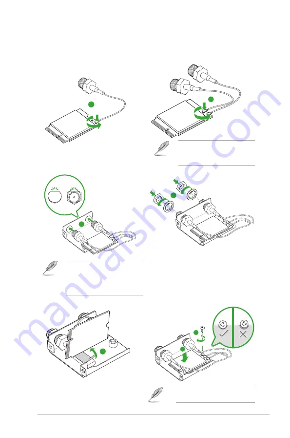
Wi-Fi card installation

1

To assemble the Wi-Fi card module

Ensure to 

connect the IPEX 

connector of the RF cable to 

the Wi-Fi card tightly

.

2

3

Align the flat side of the RF 

connector to that of the hole in the 

M.2 Key E bracket, as shown in 

the illustration, then firmly push the 

connector into the hole.

4

5

7

6

Align the notch of the Wi-Fi card 

closely to the screw hole.

Summary of Contents for Prime B460I-PLUS

Page 1: ...Motherboard PRIME B460I PLUS ...

Page 2: ...e companies and are used only for identification or explanation and to the owners benefit without intent to infringe Offer to Provide Source Code of Certain Software This product contains copyrighted software that is licensed under the General Public License GPL under the Lesser General Public License Version LGPL and or other Free Open Source Software Licenses Such software in this product is dis...

Page 3: ...Before you proceed 1 1 1 2 Motherboard overview 1 1 1 3 Central Processing Unit CPU 1 8 1 4 System memory 1 9 1 5 Wi Fi card installation 1 11 Chapter 2 BIOS and RAID Support 2 1 Knowing BIOS 2 1 2 2 BIOS Setup program 2 2 2 3 ASUS EZ Flash 3 2 3 2 4 ASUS CrashFree BIOS 3 2 4 2 5 RAID configurations 2 5 Appendix Notices A 1 ASUS contact information A 6 ...

Page 4: ...electrical outlet you are using contact your local power company If the power supply is broken do not try to fix it by yourself Contact a qualified service technician or your retailer Operation safety Before installing the motherboard and adding components carefully read all the manuals that came with the package Before using the product ensure all cables are correctly connected and the power cabl...

Page 5: ...es for additional information and for product and software updates 1 ASUS website The ASUS website provides updated information on ASUS hardware and software products Refer to the ASUS contact information 2 Optional documentation Your product package may include optional documentation such as warranty flyers that may have been added by your dealer These documents are not part of the standard packa...

Page 6: ...t 1 4 1 x HDMITM 1 4b Graphics specifications may vary between CPU types Support DisplayPort 1 4 with max resolution of 4096 x 2304 60Hz Please refer to www intel com for any update Expansion Slots Intel 10th Gen Processors 1 x PCIe 3 0 x16 slot supports x16 mode Storage Total supports 1 x M 2 slot and 4 x SATA 6Gb s ports Intel B460 Chipset M 2 slot Key M type 2260 2280 supports PCIe 3 0 x4 mode ...

Page 7: ... panel is required to support 7 1 Surround Sound audio output Back Panel I O Ports 4 x USB 3 2 Gen 1 ports 4 x Type A 2 x USB 2 0 ports 2 x Type A 1 x DisplayPort 1 x HDMITM port 1 x Realtek RTL8111H 1Gb Ethernet port 3 x Audio jacks 1 x PS 2 Keyboard Mouse combo port Internal I O Connectors Fan and cooling related 1 x 4 pin CPU Fan header 1 x 4 pin AIO Fan header 1 x 4 pin Chassis Fan header Powe...

Page 8: ...r Software Features ASUS Exclusive Software Armoury Crate AURA Sync AI Suite 3 Performance and Power Saving Utility TurboV EVO EPU DIGI VRM Fan Xpert 4 EZ update ASUS CPU Z AI Charger DAEMON Tools Norton Anti virus software Free Trial for 60 days WinRAR UEFI BIOS ASUS EZ DIY ASUS CrashFree BIOS 3 ASUS EZ Flash 3 ASUS UEFI BIOS EZ Mode BIOS 128 Mb Flash ROM UEFI AMI BIOS Manageability WOL by PME PX...

Page 9: ...ply Failure to do so may cause severe damage to the motherboard peripherals or components Unplug the power cord before installing or removing the motherboard Failure to do so can cause you physical injury and damage motherboard components 1 2 Motherboard overview Place this side towards the rear of the chassis 17 0cm 6 7in 17 0cm 6 7in EATXPWR RGB_HEADER DDR4 DIMM_A1 64bit 288 pin module M 2 SOCKE...

Page 10: ...wn firmly until the power supply plugs are fully inserted Ensure to connect the 8 pin power plug For a fully configured system we recommend that you use a power supply unit PSU that complies with ATX 12V Specification 2 0 or later version and provides a minimum power of 350 W We recommend that you use a PSU with a higher power output when configuring a system with more power consuming devices The ...

Page 11: ...mponent ensure that the ATX power supply is switched off or the power cord is detached from the power supply Failure to do so may cause severe damage to the motherboard peripherals or components 11 RTC Battery header 2 pin BATT_CON This header is for the lithium CMOS battery 12 Clear CMOS header This header allows you to clear the CMOS RTC RAM data of the system setup information such as date time...

Page 12: ...udio 15 M 2 slot Key E This slot allows you to install an M 2 Key E Wi Fi and Wi Fi based combo device Refer to Section 1 5 Wi Fi card installation for details 16 Speaker header The 4 pin header is for the chassis mounted system warning speaker The speaker allows you to hear system beeps and warnings 17 SPI TPM header This header supports a Trusted Platform Module TPM system with a Serial Peripher...

Page 13: ... mode Hard disk drive activity LED 2 pin HDD_LED This 2 pin header is for the HDD Activity LED Connect the HDD Activity LED cable to this header The HDD LED lights up or flashes when data is read from or written to the HDD Power button Soft off button 2 pin PWR_BTN This header is for the system power button Reset button 2 pin RESET This 2 pin header is for the chassis mounted reset button for syst...

Page 14: ...o a Local Area Network LAN through a network hub Refer to the table below for the Ethernet port LED indications Ethernet port LED indications 4 Line In port light blue This port connects the tape CD DVD player or other audio sources 5 Line Out port lime This port connects a headphone or a speaker In 4 channel 5 1 channel and 7 1 channel configurations the function of this port becomes Front Speake...

Page 15: ...ation Port Headset 2 channel 4 channel 5 1 channel 7 1 channel Light Blue Rear panel Line In Rear Speaker Out Rear Speaker Out Rear Speaker Out Lime Rear panel Line Out Front Speaker Out Front Speaker Out Front Speaker Out Pink Rear panel Mic In Mic In Bass Center Bass Center Lime Front panel Side Speaker Out To configure a 7 1 channel audio output A chassis with an HD audio module in the front pa...

Page 16: ...e socket and the socket contacts are not bent Contact your retailer immediately if the PnP cap is missing or if you see any damage to the PnP cap socket contacts motherboard components Keep the cap after installing the motherboard ASUS will process Return Merchandise Authorization RMA requests only if the motherboard comes with the cap on the LGA1200 socket The product warranty does not cover dama...

Page 17: ...compatibility we recommend that you install memory modules of the same version or date code D C from the same vendor Check with the retailer to get the correct memory modules DDR4 will run at max 2933 MHz on Intel 10th Generation 8 core or higher processors The default memory operation frequency is dependent on its Serial Presence Detect SPD which is the standard way of accessing information from ...

Page 18: ...1 10 Chapter 1 Product introduction Installing a DIMM 1 2 B A A To remove a DIMM B A ...

Page 19: ...o connect the IPEX connector of the RF cable to the Wi Fi card tightly 2 3 Align the flat side of the RF connector to that of the hole in the M 2 Key E bracket as shown in the illustration then firmly push the connector into the hole 4 5 7 6 Align the notch of the Wi Fi card closely to the screw hole ...

Page 20: ... Wi Fi card module before installing your motherboard to the chassis The Wi Fi card RF cable and antenna are purchased separately To install the Wi Fi card module to your motherboard Insert the Wi Fi card to the M 2 Key E slot then secure the module with screws from the bottom side of the motherboard 8 BOTTOM 9 ...

Page 21: ...MOS In normal circumstances the default BIOS settings apply to most conditions to ensure optimal performance DO NOT change the default BIOS settings except in the following circumstances An error message appears on the screen during the system bootup and requests you to run the BIOS Setup You have installed a new system component that requires further BIOS settings or update Inappropriate BIOS set...

Page 22: ...ly if you failed to enter BIOS Setup using the first two options After doing either of the three options press Delete key to enter BIOS Ensure that a USB mouse is connected to your motherboard if you want to use the mouse to control the BIOS setup program If the system becomes unstable after changing any BIOS setting load the default settings to ensure system compatibility and stability Select the...

Page 23: ...r reset the system while updating the BIOS to prevent system boot failure 1 Insert the USB flash disk that contains the latest BIOS file to the USB port 2 Enter the Advanced Mode of the BIOS setup program Go to the Tool menu to select ASUS EZ Flash 3 Utility and press Enter 3 Select via Storage Device s 4 Press Tab to switch to the Drive field 5 Press the Up Down arrow keys to find the USB flash d...

Page 24: ...e download the file at https www asus com support and save it to a USB flash drive Recovering the BIOS To recover the BIOS 1 Turn on the system 2 Insert the motherboard support DVD to the optical drive or the USB flash drive containing the BIOS file to the USB port 3 The utility automatically checks the devices for the BIOS file When found the utility reads the BIOS file and enters ASUS EZ Flash 3...

Page 25: ...erance to the entire system Use two new drives or use an existing drive and a new drive for this setup The new drive must be of the same size or larger than the existing drive RAID 5 stripes both data and parity information across three or more hard disk drives Among the advantages of RAID 5 configuration include better HDD performance fault tolerance and higher storage capacity The RAID 5 configu...

Page 26: ...2 6 Chapter 2 BIOS information ...

Page 27: ...ence in a residential installation This equipment generates uses and can radiate radio frequency energy and if not installed and used in accordance with the instructions may cause harmful interference to radio communications However there is no guarantee that interference will not occur in a particular installation If this equipment does cause harmful interference to radio or television reception ...

Page 28: ...ference that may cause undesired operation of the device CAN ICES 3 B NMB 3 B Déclaration de conformité de Innovation Sciences et Développement économique Canada ISED Le présent appareil est conforme aux CNR d Innovation Sciences et Développement économique Canada applicables aux appareils radio exempts de licence L exploitation est autorisée aux deux conditions suivantes 1 l appareil ne doit pas ...

Page 29: ...mation disclosure based on regulation requirements ASUS is complied with EU REACH and Article 33 Complying with the REACH Registration Evaluation Authorisation and Restriction of Chemicals regulatory framework we published the chemical substances in our products at ASUS REACH website at http csr asus com english REACH htm EU RoHS This product complies with the EU RoHS Directive For more details se...

Page 30: ...T throw the motherboard in municipal waste This product has been designed to enable proper reuse of parts and recycling This symbol of the crossed out wheeled bin indicates that the product electrical and electronic equipment should not be placed in municipal waste Check local regulations for disposal of electronic products DO NOT throw the mercury containing button cell battery in municipal waste...

Page 31: ...етствующим условиям соответствующих директив Подробную информацию пожалуйста смотрите на www asus com support Български С настоящото ASUSTeK Computer Inc декларира че това устройство е в съответствие със съществените изисквания и другите приложими постановления на свързаните директиви Пълният текст на декларацията за съответствие на ЕС е достъпна на адрес www asus com support Hrvatski ASUSTeK Comp...

Page 32: ...USA Telephone 1 510 739 3777 Fax 1 510 608 4555 Web site https www asus com us Technical Support Support fax 1 812 284 0883 Telephone 1 812 282 2787 Online support https qr asus com techserv ASUS COMPUTER GmbH Germany and Austria Address Harkortstrasse 21 23 40880 Ratingen Germany Web site https www asus com de Online contact https www asus com support Product ContactUs Services questionform lang ...

Reviews: