


ROG R
ampage Formula
2-33
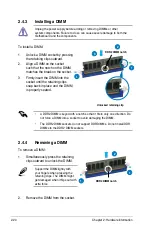
7. CPU, chassis, and optional fan connectors
(4-pin CPU_FAN, 3-pin CHA_FAN1~3, 3-pin PWR_FAN,
3-pin OPT_FAN1~3)
The fan connectors support cooling fans of 350 mA~1000 mA (24 W max.) or
a total of 1 A~3.48 A (41.76 W max.) at +12V. Connect the fan cables to the
fan connectors on the motherboard, making sure that the black wire of each
cable matches the ground pin of the connector.
DO NOT forget to connect the fan cables to the fan connectors. Insufficient air
flow inside the system may damage the motherboard components. These are
not jumpers! DO NOT place jumper caps on the fan connectors!
• Only the CPU_FAN, CHA_FAN1~3, and OPT_FAN1~3 connectors support
the ASUS Q-Fan 2 feature.
• If you install two VGA cards, we recommend that you plug the chassis fan
cable to the motherboard connector labled CHA_FAN1 or CHA_FAN3 for
better themal environment.
RAMPAGE FORMULA
®
RAMPAGE FORMULA Fan connectors
CPU_FAN
GND CPU F
AN PWR
CPU F
AN IN
CPU F
AN PWM
PWR_FAN
OPT_FAN1
OPT_FAN2
GND
Rotation
+12V
CHA_FAN2
GND
Rotation
+12V
CPU_FAN
PWR_FAN
CHA_FAN3
CHA_FAN1
OPT_FAN1
OPT_FAN3
OPT_FAN2
CHA_FAN2
GND
Rotatio
n
+12V
CHA_FAN1
GND
Rotation
+12V
CHA_FAN3
GND
Rotation
+12V
GND
Rotation
+12V
GND
Rotatio
n
+12V
OPT_FAN3
Summary of Contents for PCI/E-P54NP4
Page 1: ...Motherboard Rampage Formula ...
Page 14: ...xiv ...
Page 114: ...4 44 Chapter 4 BIOS setup ...


