background image

ASUS P8H61-M LX R2.0

1-6

1.4 

Before you proceed

Take note of the following precautions before you install motherboard components or change 

any motherboard settings.

•  Unplug the power cord from the wall socket before touching any component.
•  Before handling components, use a grounded wrist strap or touch a safely grounded 

object or a metal object, such as the power supply case, to avoid damaging them due to 

static electricity.

•  Hold components by the edges to avoid touching the ICs on them.
•  Whenever you uninstall any component, place it on a grounded antistatic pad or in the 

bag that came with the component.

•  Before you install or remove any component, ensure that the ATX power supply is 

switched off or the power cord is disconnected from the power supply. Failure to do so 

may cause severe damage to the motherboard, peripherals, or components.
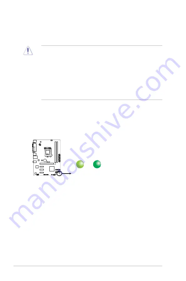
Standby Power LED

The motherboard comes with a standby power LED that lights up to indicate that the system 

is ON, in sleep mode, or in soft-off mode. This is a reminder that you should shut down 

the system and unplug the power cable before removing or plugging in any motherboard 

component. The illustration below shows the location of the onboard LED.

SB_PWR

ON

Standby Power Powered Off

OFF

P8H61-M LX R2.0

P8H61-M LX R2.0 Onboard LED

Summary of Contents for P8H61-I LX R2.0 RM SI

Page 1: ...Motherboard P8H61 M LX R2 0 P8H61 M PLUS R2 0 P8H61 M LX R2 0 Series ...

Page 2: ...pective companies and are used only for identification or explanation and to the owners benefit without intent to infringe Offer to Provide Source Code of Certain Software This product contains copyrighted software that is licensed under the General Public License GPL under the Lesser General Public License Version LGPL and or other Free Open Source Software Licenses Such software in this product ...

Page 3: ...5 4 Layout contents 1 8 1 6 Central Processing Unit CPU 1 9 1 6 1 Installing the CPU 1 10 1 6 2 Installing the CPU heatsink and fan 1 13 1 6 3 Uninstalling the CPU heatsink and fan 1 14 1 7 System memory 1 15 1 7 1 Overview 1 15 1 7 2 Memory configurations 1 16 1 7 3 Installing a DIMM 1 23 1 7 4 Removing a DIMM 1 23 1 8 Expansion slots 1 24 1 8 1 Installing an expansion card 1 24 1 8 2 Configuring...

Page 4: ...ity 2 10 2 4 Ai Tweaker menu 2 13 2 4 1 Memory Frequency Auto 2 14 2 4 2 EPU Power Saving Mode Disabled 2 14 2 4 3 OC Tuner 2 14 2 4 4 DRAM Timing Control 2 14 2 4 5 CPU Power Management 2 14 2 4 6 DIGI VRM 2 15 2 4 7 CPU Voltage Offset Mode 2 17 2 4 8 Offset Mode Sign 2 17 2 4 9 iGPU Voltage Offset Mode 2 17 2 4 10 iGPU Offset Mode Sign 2 17 2 4 11 DRAM Voltage Auto 2 17 2 4 12 VCCSA Voltage Auto...

Page 5: ...Voltage 2 27 2 6 6 Anti Surge Support Enabled 2 27 2 7 Boot menu 2 28 2 7 1 Bootup NumLock State On 2 28 2 7 2 Full Screen Logo Enabled 2 28 2 7 3 Wait for F1 If Error Enabled 2 28 2 7 4 Option ROM Messages Force BIOS 2 29 2 7 5 Setup Mode EZ Mode 2 29 2 7 6 UEFI Legacy Boot Enable both UEFI and Legacy 2 29 2 7 7 Boot Option Priorities 2 29 2 7 8 Boot Override 2 29 2 8 Tools menu 2 30 2 8 1 ASUS E...

Page 6: ...f you are not sure about the voltage of the electrical outlet you are using contact your local power company If the power supply is broken do not try to fix it by yourself Contact a qualified service technician or your retailer Operation safety Before installing the motherboard and adding components carefully read all the manuals that came with the package Before using the product ensure that all ...

Page 7: ...tains the following parts Chapter 1 Product introduction This chapter describes the supported features of the motherboard Chapter 2 BIOS information This chapter provides a detailed guide to navigating and setting up the BIOS DANGER WARNING Information to prevent injury to yourself when completing a task CAUTION Information to prevent damage to the components when completing a task NOTE Tips and a...

Page 8: ...key names are linked with a plus sign Example Ctrl Alt Del Typography Where to find more information Refer to the following sources for additional information and for product and software updates 1 ASUS websites The ASUS website provides updated information on ASUS hardware and software products Refer to the ASUS contact information 2 Optional documentation Your product package may include optiona...

Page 9: ...ed Vendor List When you install memory of 4GB capacity or more Windows 32 bit operating system may only recognize less than 3GB We recommend a maximum of 3GB system memory if you are using a Windows 32 bit operating system Graphics Supports RGB with max resolution 2048 x1536 75GHz Intel Quick Sync Video Technology Support Expansion slots 1 x PCI Express 3 0 2 0 x16 slot blue at x16 mode 3 x PCI Ex...

Page 10: ...o 2 ASUS Exclusive Overclocking ASUS C P R CPU Parameter Recall Internal connectors switches buttons 2 x USB 2 0 1 1 connectors support additional 4 USB 2 0 1 1 ports 4 x SATA 3 0 Gb s connectors 1 x CPU fan connector 1 x Chassis fan connector 1 x Front panel audio connector 1 x S PDIF Out connector 1 x speaker connector 1 x System panel connector 1 x 24 pin EATX power connector 1 x 4 pin ATX 12V ...

Page 11: ...tel second generation Core i7 Core i5 Core i3 processors are among the most powerful and energy efficient CPUs in the world 1 1 Welcome Thank you for buying an ASUS P8H61 M LX R2 0 Series motherboard The motherboard delivers a host of new features and the latest technologies making it another standout in the long line of ASUS quality motherboards Before you start installing the motherboard and add...

Page 12: ... encoding schemes that provide twice the performance of the current PCIe 2 0 The total bandwidth for a x16 link reaches a maximum of 32Gb s double the 16 Gb s of PCIe 2 0 in x16 mode As such PCIe 3 0 provides users unprecendented data speeds combined with the convenience and seamless transition offerred by complete backward compatibility with PCIe 1 0 and PCIe 2 0 devices PCIe 3 0 will become a mu...

Page 13: ...ance to its full potential ASUS EPU Tap into the world s first real time PC power saving chip through a simple oboard switch or AI Suite II utility Get total system wide energy optimization by automatically detecting current PC loadings and intelligently moderating power consumption This also reduces fan noise and extends component longevity 1 3 3 Innovative ASUS features ASUS UEFI BIOS EZ Mode Th...

Page 14: ...users an extremely silent and cooling experience with an elegant appearance ESD Protect Your Computer with ESD Guards Electrostatic discharge ESD conditions can happen while plugging or unplugging any USB peripherals causing damage to the computer ASUS ESD Guards clamp the ESD voltage and shunt the majority of the ESD current away for a more reliable computing environment Low EMI A special low rad...

Page 15: ... when the system hangs due to overclocking failure C P R eliminates the need to open the system chassis and clear the RTC data Simply shut down and reboot the system and the BIOS automatically restores the CPU parameters to their default settings ErP ready The motherboard is European Union s Energy related Products ErP ready and ErP requires products to meet certain energy efficiency requirements ...

Page 16: ...a grounded antistatic pad or in the bag that came with the component Before you install or remove any component ensure that the ATX power supply is switched off or the power cord is disconnected from the power supply Failure to do so may cause severe damage to the motherboard peripherals or components Standby Power LED The motherboard comes with a standby power LED that lights up to indicate that ...

Page 17: ...mage motherboard components 1 5 1 Placement direction When installing the motherboard ensure that you place it into the chassis in the correct orientation The edge with external ports goes to the rear part of the chassis as indicated in the image below 1 5 2 Screw holes Secure the motherboard to the chassis using six screws as indicated by the circles in the illustration below Do not overtighten t...

Page 18: ...pin USB56 USB78 1 23 5 Intel H61 Serial ATA 3 0Gb s connectors 7 pin SATA3G_1 2 3 4 1 24 11 Digital audio connector 4 1 pin SPDIF_OUT 1 24 6 Standby power LED SB_PWR 1 1 12 Front panel audio connector 10 1 pin AAFP 1 21 P8H61 M LX R2 0 PCIEX16 PCIEX1_1 PCIEX1_2 PCIEX1_3 F_PANEL SPEAKER SPEAKER CLRTC USB78 USB56 AAFP ATX12V EATXPWR CPU_FAN CHA_FAN Lithium Cell CMOS Power Super I O ALC 887 RTL 8111E...

Page 19: ...ately if the PnP cap is missing or if you see any damage to the PnP cap socket contacts motherboard components ASUS will shoulder the cost of repair only if the damage is shipment transit related Keep the cap after installing the motherboard ASUS will process Return Merchandise Authorization RMA requests only if the motherboard comes with the cap on the LGA1155 socket The product warranty does not...

Page 20: ...t remove the PnP cap unless you are installing a CPU 2 Press the load lever with your thumb A and then move it to the right B until it is released from the retention tab A B Load lever Retention tab P8H61 M LX R2 0 P8H61 M LX R2 0 CPU socket LGA1155 3 Lift the load lever in the direction of the arrow until the load plate is completely lifted Load plate ...

Page 21: ... ensuring that the gold triangle is on the bottom left corner of the socket and then fit the socket alignment keys into the CPU notches 6 Apply some Thermal Interface Material to the exposed area of the CPU that the heatsink will be in contact with ensuring that it is spread in an even thin layer Some heatsinks come with pre applied thermal paste If so skip this step The Thermal Interface Material...

Page 22: ... M LX R2 0 1 12 7 Close the load plate A and then push down the load lever B ensuring that the front edge of the load plate slides under the retention knob C B A C 8 Insert the load lever under the retention tab ...

Page 23: ...nsion Ensure that you have installed the motherboard to the chassis before you install the CPU fan and heatsink assembly The type of CPU heatsink and fan assembly may differ but the installation steps and functions should remain the same The illustration above is for reference only To install the CPU heatsink and fan 1 Place the heatsink on top of the installed CPU ensuring that the four fasteners...

Page 24: ... 1 6 3 Uninstalling the CPU heatsink and fan To uninstall the CPU heatsink and fan 1 Disconnect the CPU fan cable from the connector on the motherboard 2 Rotate each fastener counterclockwise 3 Pull up two fasteners at a time in a diagonal sequence to disengage the heatsink and fan assembly from the motherboard A A B B A A B B CPU_FAN CPU FAN PWM CPU FAN IN CPU FAN PWR GND P8H61 M LX R2 0 P8H61 M ...

Page 25: ...prevent installation on a DDR2 DIMM socket DDR3 modules are developed for better performance with less power consumption The figure illustrates the location of the DDR3 DIMM sockets Channel Sockets Channel A DIMM_A1 Channel B DIMM_B1 P8H61 M LX R2 0 P8H61 M LX R2 0 240 pin DDR3 DIMM sockets DIMM_A1 DIMM_B1 4 Carefully remove the heatsink and fan assembly from the motherboard 5 Rotate each fastener...

Page 26: ...install varying memory sizes in Channel A and Channel B The system maps the total size of the lower sized channel for the dual channel configuration Any excess memory from the higher sized channel is then mapped for single channel operation According to Intel CPU specification DIMM voltage below 1 65V is recommended to protect the CPU Always install DIMMs with the same CAS latency For optimum comp...

Page 27: ...g Voltage DIMM socket support Optional 1 DIMM 2 DIMMs GEIL GET34GB2200C9DC XMP 2GB DS 9 10 9 28 1 65V GEIL GET38GB2200C9ADC XMP 4GB DS 9 11 9 28 1 65V KINGMAX FLKE85F B8KJA FEIH XMP 4GB 2 x 2GB DS 1 5V 1 7V DDR3 2250 MHz capability Vendors Part No Size SS DS Chip Brand Chip NO Timing Voltage DIMM socket support Optional 1 DIMM 2 DIMMs KINGSTON KHX2250C9D3T1K2 4GX XMP 4GB 2 x 2GB DS 1 65V Vendors P...

Page 28: ...9AD3W1K3 6GX XMP 6GB 3 x 2GB DS 1 65V KINGSTON KHX2000C9AD3T1K3 6GX XMP 6GB 3 x 2GB DS 1 65V Transcend TX2000KLN 8GK XMP 8GB 2 x 4GB DS 1 6V Asint SLA302G08 ML2HB XMP 4GB DS HYNIX H5TQ2G83BFR H9C DDR3 1866 MHz capability Vendors Part No Size SS DS Chip Brand Chip NO Timing Voltage DIMM socket support Optional 1 DIMM 2 DIMMs CORSAIR CMT4GX3M2A1866C9 XMP 4GB 2 x 2GB DS 9 9 9 24 1 65V CORSAIR CMT6GX3...

Page 29: ...5V G SKILL F3 12800CL9D 8GBRL XMP 8GB 2 x 4GB DS 9 9 9 24 1 5V GEIL GET316GB1600C9QC XMP 16GB 4 x 4GB DS 9 9 9 28 1 6V HYNIX HMT351U6CFR8C PB 4GB DS HYNIX H5TQ2G83CFR PBC KINGMAX FLGD45F B8MF7 MAEH XMP 1GB SS 7 KINGMAX FLGE85F B8KJ9A FEIS XMP 2GB DS KINGMAX FLGE85F B8MF7 MEEH XMP 2GB DS 7 KINGSTON KHX1600C9D3P1K2 4G 4GB 2 x 2GB SS 1 5V KINGSTON KHX1600C9D3K3 12GX XMP 12GB 3x4GB DS 9 9 9 27 1 65V K...

Page 30: ...GB 2 x 1GB DS 9 9 9 24 1 5V GEIL GG34GB1333C9DC 4GB 2 x 2GB DS GEIL GL1L128M88BA12N 9 9 9 24 1 3V low voltage GEIL GV34GB1333C9DC 4GB 2 x 2GB DS 9 9 9 24 1 5V Hynix HMT112U6TFR8A H9 1GB SS HYNIX H5TC1G83TFRH9A 1 35V low voltage HYNIX HMT325U6BFR8C H9 2GB SS HYNIX H5TQ2G83BFRH9C Hynix HMT125U6TFR8A H9 2GB DS HYNIX H5TC1G83TFRH9A 1 35V low voltage HYNIX HMT351U6BFR8C H9 4GB DS HYNIX H5TQ2G83BFRH9C K...

Page 31: ...KPT 9 9 9 24 1 5V Elixir M2F2G64CB88B7N CG 2GB DS Elixir N2CB2G808N CG Elixir M2Y2G64CB8HA9N CG 2GB DS 7 7 7 20 Elixir M2Y2G64CB8HC9N CG 2GB DS Elixir Elixir M2F4G64CB8HB5N CG 4GB DS Elixir N2CB2G808N CG KINGSHARE KSRPCD313332G 2GB DS PATRIOT PM128M8D385 15 Kingtiger 2GB DIMM PC3 10666 2GB DS Samsung SEC 904 HCH9 K4B1G0846D Kingtiger KTG2G1333PG3 2GB DS PATRIOT PSD31G13332H 1GB DS 9 PATRIOT PSD31G...

Page 32: ... J1108BDSE DJ F 7 1 5V KINGSTON KVR1066D3N7 4G 4GB DS Hynix H5TQ2G83AFR 7 1 5V Micron MT8JTF12864AZ 1G1F1 1GB SS Micron 9GF22D9KPT 7 Micron MT16JTF25664AZ 1G1F1 2GB DS Micron 9HF22D9KPT 7 OCZ OCZ3G1066LV4GK 4GB 2 x 2GB DS Micron 9BF27D9KPV 7 7 7 20 1 65V Elixir M2Y2G64CB8HC5N BE 2GB DS Elixir N2CB1G80CN BE Elixir M2Y2G64CBHA9N BE 2GB DS 7 7 7 20 Elixir M2Y2G64CBHC9N BE 2GB DS Elixir Kingtiger 2GB ...

Page 33: ...MM notch 2 1 A DIMM is keyed with a notch so that it fits in only one direction DO NOT force a DIMM into a socket in the wrong direction to avoid damaging the DIMM 3 Firmly insert the DIMM into the socket until the retaining clips snap back in place and the DIMM is properly seated Locked Retaining Clip 3 1 7 4 Removing a DIMM To remove a DIMM 1 Simultaneously press the retaining clips outward to u...

Page 34: ...the slot 5 Secure the card to the chassis with the screw you removed earlier 6 Replace the system cover 1 8 2 Configuring an expansion card After installing the expansion card configure it by adjusting the software settings 1 Turn on the system and change the necessary BIOS settings if required See Chapter 2 for information on BIOS setup 2 Assign an IRQ to the card 3 Install the software drivers f...

Page 35: ...r again to clear the CMOS RTC RAM data After clearing the CMOS reinstall the battery You do not need to clear the RTC when the system crashes due to overclocking For system failure due to overclocking use the CPU Parameter Recall C P R feature Afterwards shut down and reboot the system The BIOS automatically resets parameter settings to default values To erase the RTC RAM 1 Turn OFF the computer a...

Page 36: ... configurations the function of this port becomes Front Speaker Out 6 Microphone port pink This port connects to a microphone Activity Link LED Speed LED Status Description Status Description OFF No link OFF 10Mbps connection ORANGE Linked ORANGE 100Mbps connection BLINKING Data activity GREEN 1Gbps connection Refer to the audio configuration table below for the function of the audio ports in 2 4 ...

Page 37: ...I O module that supports either HD Audio or legacy AC 97 audio standard Connect one end of the front panel audio I O module cable to this connector We recommend that you connect a high definition front panel audio module to this connector to avail of the motherboard s high definition audio capability If you want to connect a high definition front panel audio module to this connector set the Front ...

Page 38: ... PowerSupplyCalculator PSCalculator aspx SLanguage en us for details 2 ATX power connectors 24 pin EATXPWR 4 pin ATX12V These connectors are for ATX power supply plugs The power supply plugs are designed to fit these connectors in only one orientation Find the proper orientation and push down firmly until the connectors completely fit 3 Speaker connector 4 pin SPEAKER The 4 pin connector is for th...

Page 39: ...US FanXpert feature 5 USB connectors 10 1 pin USB56 USB78 These connectors are for USB 2 0 ports Connect the USB module cable to any of these connectors then install the module to a slot opening at the back of the system chassis These USB connectors comply with USB 2 0 specification that supports up to 480 Mbps connection speed Never connect a 1394 cable to the USB connectors Doing so will damage ...

Page 40: ...lug and NCQ on Windows Vista Windows 7 set the SATA Mode item in the BIOS to AHCI Mode See section 2 5 4 SATA Configuration for details 7 Digital audio connector 4 1 pin SPDIF_OUT This connector is for an additional Sony Philips Digital Interface S PDIF port Connect the S PDIF Out module cable to this connector then install the module to a slot opening at the back of the system chassis The S PDIF ...

Page 41: ...k drive activity LED 2 pin HDLED This 2 pin connector is for the HDD Activity LED Connect the HDD Activity LED cable to this connector The IDE LED lights up or flashes when data is read from or written to the HDD Power Soft off button 2 pin PWRBTN This 2 pin connector is for the system power button Reset button 2 pin RESET This 2 pin connector is for the chassis mounted reset button for system reb...

Page 42: ...rt DVD that comes with the motherboard package contains the drivers software applications and utilities If Autorun is NOT enabled in your computer browse the contents of the Support DVD to locate the file ASSETUP EXE from the BIN folder Double click the ASSETUP EXE to run the DVD The following screen is for reference only The contents of the Support DVD are subject to change at any time without no...

Page 43: ...r and then click ASUS Update from the popup menu The ASUS Update main screen appears From the list select either of the following methods Updating from the Internet a Select Update BIOS from the Internet then click Next b Select the ASUS FTP site nearest you to avoid network traffic then click Next c From the FTP site select the BIOS version that you wish to download then click Next 2 1 1 ASUS Upd...

Page 44: ...BIOS from file then click Next b Locate the BIOS file from the Open window then click Open 3 Follow the onscreen instructions to complete the updating process To update the BIOS using EZ Flash 2 1 Insert the USB flash disk that contains the latest BIOS file to the USB port 2 Enter the Advanced Mode of the BIOS setup program Go to the Tool menu to select ASUS EZ Flash Utility and press Enter to ena...

Page 45: ...s the updated BIOS file Recovering the BIOS To recover the BIOS 1 Turn on the system 2 Insert the support DVD into the optical drive or the USB flash drive that contains the BIOS file to the USB port 3 The utility automatically checks the devices for the BIOS file When found the utility reads the BIOS file and enters ASUS EZ Flash 2 utility automatically 4 The system requires you to enter BIOS Set...

Page 46: ...BIOS Updater to a hard disk drive or USB flash drive formatted using NTFS 3 Turn off the computer and disconnect all SATA hard disk drives optional Booting the system in DOS environment 1 Insert the USB flash drive with the latest BIOS file and BIOS Updater to the USB port 2 Boot your computer When the ASUS Logo appears press F8 to show the BIOS Boot Device Select Menu Insert the support DVD into ...

Page 47: ... Down Home End keys to select the BIOS file and press Enter BIOS Updater checks the selected BIOS file and prompts you to confirm BIOS update Are you sure to update BIOS Yes No 4 Select Yes and press Enter When BIOS update is done press ESC to exit BIOS Updater Restart your computer DO NOT shut down or reset the system while updating the BIOS to prevent system boot failure For BIOS Updater version...

Page 48: ... Defaults item under the Exit menu See section 2 9 Exit Menu for details If the system fails to boot after changing any BIOS setting try to clear the CMOS and reset the motherboard to the default values See section 1 9 Jumpers for information on how to erase the RTC RAM 2 2 BIOS setup program Use the BIOS Setup program to update the BIOS or configure its settings The BIOS screens include navigatio...

Page 49: ...he Advanced Mode click Exit Advanced Mode then select Advanced Mode The default screen for entering the BIOS setup program can be changed Refer to the Setup Mode item in section 2 7 Boot menu for details Default F5 Loads optimized default settings Switches to Advanced Mode Displays list of shortcuts to BIOS functions Displays boot sequence and bootable devices Switches system performance to Quiet ...

Page 50: ...owing screens Main For changing basic system configuration Ai Tweaker For viewing and modifying overclocking settings Advanced For modifying advanced system settings such as CPU SATA and onboard devices Monitor For displaying system temperature power status and changing the fan settings Boot For modifying system boot configuration Tool For accessing additional BIOS features and functionality Exit ...

Page 51: ... side of a menu screen when there are items that do not fit on the screen Press the Up Down arrow keys or Page Up Page Down keys to display the other items on the screen Navigation keys Instructions for changing values and navigating the BIOS utility are displayed on the lower right hand corner of the screen General help At the top right corner of the menu screen is a brief description of the sele...

Page 52: ...guration options English 2 3 2 System Date Day xx xx xxxx Allows you to set the system date 2 3 3 System Time xx xx xx Allows you to set the system time 2 3 4 Security The Security menu items allow you to modify or create administrator or user passwords If you have forgotten your BIOS password erase the CMOS Real Time Clock RTC RAM to clear the BIOS password See section 1 9 Jumpers for information...

Page 53: ...ator password 1 Select Security and press Enter 2 Select Administrator Password then press Enter 3 In the pop up window enter a password Confirm the password when prompted To change an administrator password 1 Select the Administrator Password item and press Enter 2 From the Enter Current Password box key in the current password then press Enter 3 From the Create New Password box key in a new pass...

Page 54: ...word item and press Enter 2 From the Enter Current Password box key in the current password then press Enter 3 From the Create New Password box key in a new password then press Enter 4 Confirm the password when prompted To clear the user password follow the same steps as in changing a user password but press Enter when prompted to create confirm the password After you clear the password the User P...

Page 55: ...locking related items Be cautious when changing the settings of the Ai Tweaker menu items Incorrect field values can cause the system to malfunction The configuration options for this section vary depending on the CPU and DIMM model you installed on the motherboard Scroll down to display the following items ...

Page 56: ...to the default settings 2 4 5 CPU Power Management The sub items in this menu allow you to set the CPU ratio and features CPU Ratio Auto Allows you to manually adjust the maximum non turbo CPU ratio Use and keys or the numeric keypad to adjust the ratio The valid value ranges vary according to your CPU model Enhanced Intel SpeedStep Technology Enabled Allows you to enable or disable the Enhanced I...

Page 57: ...Use to adjust the value CPU Load Line Calibration Auto Load line is defined by Intel VRM spec and affects CPU voltage The CPU working voltage will decrease proportionally to CPU loading Higher value gets a higher voltage and better overclocking performance but increases the CPU and VRM thermal This item allows you to adjust the voltage range from the following percentages to boost the system perfo...

Page 58: ...mal balance Extreme Select to maintain the current VRM balance CPU Current Capability 100 Allows you to configure the total power range and extends the overclocking frequency range simultaneously Configuration options 100 110 120 DO NOT remove the thermal module when switching to Extreme and Manual Mode The thermal conditions should be monitored DO NOT remove the thermal module when switching to M...

Page 59: ...fset Voltage Auto This item appears only when you set the CPU Voltage item to Offset Mode and allows you to set the Offset voltage The values range from 0 005V to 0 635V with a 0 005V interval 2 4 11 DRAM Voltage Auto Allows you to set the DRAM voltage The values range from 1 185V to 2 135V with a 0 005V interval According to Intel CPU specification DIMMs with voltage requirement over 1 65V may da...

Page 60: ...tically detects The items shown in submenu may be different due to the CPU you installed 2 4 14 CPU PLL Voltage Auto Allows you to set the CPU and PCH PLL voltage The values range from 1 80V to 1 90V with a 0 1V interval Configuration options Auto 0 1V The values of the CPU Manual Voltage CPU Offset Voltage iGPU Manual Voltage iGPU Offset Voltage DRAM Voltage VCCSA Voltage and PCH Voltage items ar...

Page 61: ...bled Disables this function Execute Disable Bit Enabled Enabled Enables the No Execution Page Protection Technology Disabled Forces the XD feature flag to always return to zero 0 Enhanced Intel SpeedStep Technology Enabled Allows you to enable or disable the Enhanced Intel SpeedStep Technology EIST Disabled The CPU runs at its default speed Enabled The operating system controls the CPU speed Turbo...

Page 62: ...Disabled CPU C6 Report Auto Allows you to disable or enable the CPU C6 report to the operating system Configuration options Enabled Disabled Intel Virtualization Technology Disabled Enabled Allows a hardware platform to run multiple operating systems separately and simultaneously enabling one system to virtually function as several systems Disabled Disables this function ...

Page 63: ... drive to internally optimize the order of commands 2 5 3 SATA Configuration While entering Setup the BIOS automatically detects the presence of SATA devices The SATA Port items show Not Present if no SATA device is installed to the corresponding SATA port Due to H61 Chipset limitation AHCI Mode only works on Windows Vista Windows 7 Please use IDE Mode on Windows XP IDE is the default SATA type Un...

Page 64: ...ices Configuration options Auto IGFX PEG iGPU Memory 64M Allows you to set the iGPU memory size Configuration options 32M 64M 96M 128M 160M 192M 224M 256M 288M 320M 352M 384M 416M 448M 480M 512M Render Standby Enabled Allows you to enable or disable Render Standby by internal graphics devices Configuration options Disabled Enabled IGPU Multi Monitor Allows you to enable or disable Internal Graphic...

Page 65: ...the function 2 5 6 Onboard Devices Configuration HD Audio Controller Enabled Enabled Enables the High Definition Audio Controller Disabled Disables the controller The following two items appear only when you set the HD Audio Controller item to Enabled Front Panel Type HD Allows you to set the front panel audio connector AAFP mode to legacy AC 97 or high definition audio depending on the audio stan...

Page 66: ...l port LPT LPTE Configuration options Enabled Disabled Change Settings IO 3F8h IRQ 4 Allows you to select an optimal setting for Super I O devices Configuration options Auto IO 378h IRQ 5 IO 378h IRQ 5 6 7 9 10 11 12 IO 278h IRQ 5 6 7 9 10 11 12 IO 3BCh IRQ 5 6 7 9 10 11 12 Device Mode STD Printer Mode Allows you to select the Printer Port mode Configuration options STD Printer Mode SPP Mode EPP 1...

Page 67: ... provides at least 1A on the 5VSB lead Power On By PS 2 Mouse Disabled Disabled Disables the Power On by a PS 2 mouse Enabled Enables the Power On by a PS 2 mouse This feature requires an ATX power supply that provides at least 1A on the 5VSB lead Power On By PCIE Disabled Disabled Disables the PCIE devices to generate a wake event Enabled Enables the PCIE devices to generate a wake event Power On...

Page 68: ...The onboard hardware monitor automatically detects and displays the CPU and chassis fan speeds in rotations per minute RPM If the fan is not connected to the motherboard the field shows N A Select Ignore if you do not wish to display the detected speed 2 6 3 CPU Q Fan Control Enabled Disabled Disables the CPU Q Fan control feature Enabled Enables the CPU Q Fan control feature 2 6 Monitor menu The ...

Page 69: ...rature 70 Use the and keys to adjust the upper limit of the CPU temperature The values range from 20ºC to 75ºC CPU Fan Max Duty Cycle 100 Use the and keys to adjust the maximum CPU fan duty cycle The values range from 20 to 100 When the CPU temperature reaches the upper limit the CPU fan will operate at the maximum duty cycle CPU Lower Temperature 20 Use the and keys to adjust the lower limit of t...

Page 70: ...the full screen logo display feature Set this item to Enabled to use the ASUS MyLogo 2 feature Post Report 5 sec This item appears only when the Full Screen Logo item is set to Disabled and allows you to set the waiting time for the system to display the post report Configuration options 1 sec 2 sec 3 sec 4 sec 5 sec 6 sec 7 sec 8 sec 9 sec 10 sec Until Press ESC 2 7 3 Wait for F1 If Error Enabled...

Page 71: ...rogram 2 7 6 UEFI Legacy Boot Enable both UEFI and Legacy Enabled both UEFI and Legacy Enables both UEFI and Legacy boot Disabled UEFI Enables the Legacy boot and disables the UEFI boot Disabled Legacy Enables the UEFI booth and disables the Legacy boot 2 7 7 Boot Option Priorities These items specify the boot device priority sequence from the available devices The number of device items that appe...

Page 72: ...2 8 3 ASUS O C Profile This item allows you to store or load multiple BIOS settings The Setup Profile Status items show Not Installed if no profile is created DO NOT shut down or reset the system while updating the BIOS to prevent the system boot failure We recommend that you update the BIOS file only coming from the same memory CPU configuration and BIOS version Save to Profile Allows you to save...

Page 73: ... are finished making your selections choose this option from the Exit menu to ensure the values you selected are saved When you select this option or if you press F10 a confirmation window appears Select Yes to save changes and exit Discard Changes Exit This option allows you to exit the Setup program without saving your changes When you select this option or if you press Esc a confirmation window...

Page 74: ...2 32 ASUS P8H61 M LX R2 0 ...

Page 75: ...t from that to which the receiver is connected Consult the dealer or an experienced radio TV technician for help The use of shielded cables for connection of the monitor to the graphics card is required to assure compliance with FCC regulations Changes or modifications to this unit not expressly approved by the party responsible for compliance could void the user s authority to operate this equipm...

Page 76: ...heck local regulations for disposal of electronic products DO NOT throw the mercury containing button cell battery in municipal waste This symbol of the crossed out wheeled bin indicates that the battery should not be placed in municipal waste REACH Complying with the REACH Registration Evaluation Authorisation and Restriction of Chemicals regulatory framework we published the chemical substances ...

Page 77: ...Way Fremont CA 94539 USA Telephone 1 510 739 3777 Fax 1 510 608 4555 Web site usa asus com Technical Support Telephone 1 812 282 2787 Support fax 1 812 284 0883 Online support support asus com ASUS COMPUTER GmbH Germany and Austria Address Harkort Str 21 23 D 40880 Ratingen Germany Fax 49 2102 959911 Web site www asus de Online contact www asus de sales Technical Support Telephone 49 1805 010923 S...

Page 78: ...302 326 3 V1 3 1 2007 09 EN 301 357 2 V1 3 1 2006 05 EN 302 623 V1 1 1 2009 01 2006 95 EC LVD Directive EN 60950 1 A11 2009 EN 60950 1 A12 2011 EN 60065 2002 A1 2006 A11 2008 EN 60065 2002 A12 2011 2009 125 EC ErP Directive Regulation EC No 1275 2008 EN 62301 2005 Regulation EC No 642 2009 EN 62301 2005 Regulation EC No 278 2009 EN 62301 2005 Ver 111121 CE marking Declaration Date Apr 13 2012 Year...

Reviews: