


A S U S P 5 V 8 0 0 - M X
A S U S P 5 V 8 0 0 - M X
A S U S P 5 V 8 0 0 - M X
A S U S P 5 V 8 0 0 - M X
A S U S P 5 V 8 0 0 - M X
1 - 1 3
1 - 1 3
1 - 1 3
1 - 1 3
1 - 1 3
1.6.3
1.6.3
1.6.3
1.6.3
1.6.3
Uninstalling the CPU heatsink and fan
Uninstalling the CPU heatsink and fan
Uninstalling the CPU heatsink and fan
Uninstalling the CPU heatsink and fan
Uninstalling the CPU heatsink and fan
To uninstall the CPU heatsink and fan:
1.
Disconnect the CPU fan
cable from the connector
on the motherboard labeled
CPU_FAN1.
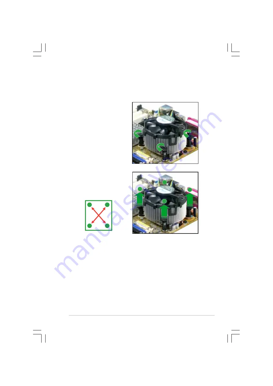
2.
Rotate each fastener
counterclockwise.
3.
Pull up two fasteners at a
time in a diagonal sequence
to disengage the heatsink
and fan assembly from the
motherboard.
A
A
B
B
B
B
A
A
Summary of Contents for P5V800-MX
Page 1: ...Motherboard P5V800 MX ...
Page 12: ...x i i x i i x i i x i i x i i ...


