background image

A S U S   P 5 P 8 0 0 S

A S U S   P 5 P 8 0 0 S

A S U S   P 5 P 8 0 0 S

A S U S   P 5 P 8 0 0 S

A S U S   P 5 P 8 0 0 S

1 - 3 1

1 - 3 1

1 - 3 1

1 - 3 1

1 - 3 1

1 0 .

1 0 .

1 0 .

1 0 .

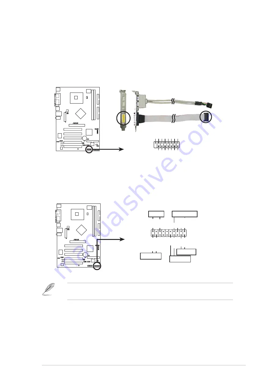
1 0 . GAME/MIDI port connector (16-1 pin GAME)

G A M E / M I D I   p o r t   c o n n e c t o r   ( 1 6 - 1   p i n   G A M E )

G A M E / M I D I   p o r t   c o n n e c t o r   ( 1 6 - 1   p i n   G A M E )

G A M E / M I D I   p o r t   c o n n e c t o r   ( 1 6 - 1   p i n   G A M E )

G A M E / M I D I   p o r t   c o n n e c t o r   ( 1 6 - 1   p i n   G A M E )

This connector is for a GAME/MIDI port. Connect the USB/GAME
module cable to this connector, then install the module to a slot
opening at the back of the system chassis. The GAME/MIDI port
connects a joystick or game pad for playing games, and MIDI devices
for playing or editing audio files.

P5P800S

®

P5P800S Game connector

GAME

+5V

+5V

J2B1

J2CX

MIDI_OUT

J2CY

J2B2

MIDI_IN

J1B1

J1CX

GND

GND

J1CY

J1B2

+5V

1 1 .

1 1 .

1 1 .

1 1 .

1 1 . System panel connector (20-1 pin PANEL)

S y s t e m   p a n e l   c o n n e c t o r   ( 2 0 - 1   p i n   P A N E L )

S y s t e m   p a n e l   c o n n e c t o r   ( 2 0 - 1   p i n   P A N E L )

S y s t e m   p a n e l   c o n n e c t o r   ( 2 0 - 1   p i n   P A N E L )

S y s t e m   p a n e l   c o n n e c t o r   ( 2 0 - 1   p i n   P A N E L )

This connector supports several chassis-mounted functions.

The sytem panel connector is color-coded for easy connection. Refer to
the connector description below for details.

P5P800S

®

P5P800S System Panel connector

Requires an ATX power supply.

PLED-

PWR

+5V

Speaker

PLED

Ground

RESET

Ground

Reset

Ground

Ground

PLED+

IDE_LED-

IDE_LED

SPEAKER

PWRSW

PANEL

S y s t e m   p o w e r   L E D   ( 3 - p i n   P L E D )

S y s t e m   p o w e r   L E D   ( 3 - p i n   P L E D )

S y s t e m   p o w e r   L E D   ( 3 - p i n   P L E D )

S y s t e m   p o w e r   L E D   ( 3 - p i n   P L E D )

S y s t e m   p o w e r   L E D   ( 3 - p i n   P L E D )
This 3-pin connector is for the system power LED. Connect the
chassis power LED cable to this connector. The system power LED
lights up when you turn on the system power, and blinks when the
system is in sleep mode.

Summary of Contents for P5P800S

Page 1: ...Motherboard P5P800S ...

Page 2: ...RS EMPLOYEES OR AGENTS BE LIABLE FOR ANY INDIRECT SPECIAL INCIDENTAL OR CONSEQUENTIAL DAMAGES INCLUDING DAMAGES FOR LOSS OF PROFITS LOSS OF BUSINESS LOSS OF USE OR DATA INTERRUPTION OF BUSINESS AND THE LIKE EVEN IF ASUS HAS BEEN ADVISED OF THE POSSIBILITY OF SUCH DAMAGES ARISING FROM ANY DEFECT OR ERROR IN THIS MANUAL OR PRODUCT SPECIFICATIONS AND INFORMATION CONTAINED IN THIS MANUAL ARE FURNISHED...

Page 3: ...1 Product highlights 1 2 1 3 2 Innovative ASUS features 1 4 1 4 Before you proceed 1 5 1 5 Motherboard overview 1 6 1 5 1 Placement direction 1 6 1 5 2 Screw holes 1 6 1 5 3 Motherboard layout 1 7 1 6 Central Processing Unit CPU 1 8 1 6 1 Installling the CPU 1 8 1 6 2 Installling the CPU heatsink and fan 1 11 1 6 3 Uninstalling the CPU heatsink and fan 1 13 1 7 System memory 1 15 1 7 1 Overview 1 ...

Page 4: ...tility 2 8 2 2 BIOS setup program 2 11 2 2 1 BIOS menu screen 2 12 2 2 2 Menu bar 2 12 2 2 3 Navigation keys 2 12 2 2 4 Menu items 2 13 2 2 5 Sub menu items 2 13 2 2 6 Configuration fields 2 13 2 2 7 Pop up window 2 13 2 2 8 Scroll bar 2 13 2 2 9 General help 2 13 2 3 Main menu 2 14 2 3 1 System Time 2 14 2 3 2 System Date 2 14 2 3 3 Legacy Diskette A 2 14 2 3 4 Primary Third and Fourth IDE Master...

Page 5: ...6 Boot menu 2 33 2 6 1 Boot Device Priority 2 33 2 6 2 Boot Settings Configuration 2 34 2 6 3 Security 2 35 2 7 Exit menu 2 38 Chapter 3 Software support Chapter 3 Software support Chapter 3 Software support Chapter 3 Software support Chapter 3 Software support 3 1 Installing an operating system 3 2 3 2 Support CD information 3 2 3 2 1 Running the support CD 3 2 3 2 2 Drivers menu 3 3 3 2 3 Utilit...

Page 6: ...r is encouraged to try to correct the interference by one or more of the following measures Reorient or relocate the receiving antenna Increase the separation between the equipment and receiver Connect the equipment to an outlet on a circuit different from that to which the receiver is connected Consult the dealer or an experienced radio TV technician for help Canadian Department of Communications...

Page 7: ...ect voltage in your area If you are not sure about the voltage of the electrical outlet you are using contact your local power company If the power supply is broken do not try to fix it by yourself Contact a qualified service technician or your retailer Operation safety Operation safety Operation safety Operation safety Operation safety Before installing the motherboard and adding devices on it ca...

Page 8: ...to change system settings through the BIOS Setup menus Detailed descriptions of the BIOS parameters are also provided Chapter 3 Software support Chapter 3 Software support Chapter 3 Software support Chapter 3 Software support Chapter 3 Software support This chapter describes the contents of the support CD that comes with the motherboard package Where to find more information Where to find more inf...

Page 9: ... Tips and additional information to help you complete a task IMPORTANT IMPORTANT IMPORTANT IMPORTANT IMPORTANT Instructions that you MUST follow to complete a task Bold text Bold text Bold text Bold text Bold text Indicates a menu or an item to select Italics Used to emphasize a word or a phrase Key Keys enclosed in the less than and greater than sign means that you must press the enclosed key Exa...

Page 10: ... Compatible with the Intel PCG 04A and 04B processors Supports Intel Hyper Threading Technology Northbridge Intel 848P Southbridge Intel ICH5 800 533 MHz 2 x 184 pin DIMM sockets support up to 2GB of unbufferred non ECC 400 333 266 MHz DDR DIMMs 1 x AGP 8x 1 5V and 0 8V only 5 x PCI slots 2 x Ultra DMA 100 66 33 2 x Serial ATA ADI AD1888 SoundMAX 6 channel CODEC S PDIF out interface support Realte...

Page 11: ...upport CD Support CD Support CD Support CD contents contents contents contents contents 3 Mb Flash ROM AMI BIOS PnP WfM2 0 DMI2 0 SM BIOS 2 3 ASUS EZ Flash CrashFree BIOS2 C P R CPU Parameter Recall ASUS MyLogo PCI 2 2 USB 2 0 WfM 2 0 DMI 2 0 WOL by PME WOR by PME Chassis Intrussion 2 x USB 2 0 connectors for 4 additional USB 2 0 ports 1 x CPU fan connector 1 x Chassis fan connector 1 x 20 pin ATX...

Page 12: ...x i i x i i x i i x i i x i i ...

Page 13: ...ASUS P5P800S ASUS P5P800S ASUS P5P800S ASUS P5P800S ASUS P5P800S 1 1 1 1 1 1 1 1 1 1 1 Product introduction This chapter describes the motherboard features and the new technologies it supports ...

Page 14: ...gnal cables 1 x Ultra DMA 100 66 33 cables 1 x Floppy disk drive cable Accessories Accessories Accessories Accessories Accessories I O shield Application CDs Application CDs Application CDs Application CDs Application CDs ASUS motherboard support CD Documentation Documentation Documentation Documentation Documentation User guide If any of the above items is damaged or missing contact your retailer...

Page 15: ...duced voltage requirement and up to 150 MB s data transfer rate See page 1 26 for details 6 channel audio support 6 channel audio support 6 channel audio support 6 channel audio support 6 channel audio support The motherboard comes with the ADI AD1888 SoundMAX audio CODEC that lets you enjoy high quality 6 channel audio without having to buy advanced sound cards The ADI SoundMAX Digital Audio Syst...

Page 16: ...ll The C P R feature of the motherboard BIOS allows automatic re setting to the BIOS default settings in case the system hangs due to overclocking When the system hangs due to overclocking C P R eliminates the need to open the system chassis and clear the RTC data Simply shut down and reboot the system and BIOS automatically restores the CPU s previous setting for each parameter AGP 8X support AGP...

Page 17: ...ectricity Hold components by the edges to avoid touching the ICs on them Whenever you uninstall any component place it on a grounded antistatic pad or in the bag that came with the component Before you install or remove any component ensure Before you install or remove any component ensure Before you install or remove any component ensure Before you install or remove any component ensure Before yo...

Page 18: ... 1 1 5 1 1 5 1 1 5 1 Placement direction Placement direction Placement direction Placement direction Placement direction When installing the motherboard make sure that you place it into the chassis in the correct orientation The edge with external ports goes to the rear part of the chassis as indicated in the image below 1 5 2 1 5 2 1 5 2 1 5 2 1 5 2 Screw holes Screw holes Screw holes Screw holes...

Page 19: ...P CPU_FAN FP_AUDIO AD1888 GAME CLRTC PRI_IDE SEC_IDE ATXPWR DDR DIMM1 64 bit 184 pin module CHA_FAN Intel ICH5 USB56 SB_PWR USBPW78 20 8cm 8 2in 30 5cm 12 0in DDR DIMM2 64 bit 184 pin module USB12 PS 2KBMS T Mouse B Keyboard SPDIF_O PARALLEL PORT COM1 PCI2 PCI3 PCI4 PCI5 Intel 848P ATX12V CR2032 3V Lithium Cell CMOS Power USB78 Below Mic In Center Line Out Top Line In SATA1 SATA2 USBPW56 RTL8100C ...

Page 20: ...this section do not match the CPU documentation follow the latter Upon purchase of the motherboard make sure that the PnP cap is on the socket and the socket pins are not bent Contact your retailer immediately if the PnP cap is missing or if you see any damage to the PnP cap socket pins motherboard components ASUS will shoulder the cost of repair only if the damage is shipment transit related Keep...

Page 21: ...t into the CPU notch 2 Press the load lever with your thumb A and move it to the left B until it is released from the retention tab Retention tab Retention tab Retention tab Retention tab Retention tab Load lever Load lever Load lever Load lever Load lever This side of the cam This side of the cam This side of the cam This side of the cam This side of the cam box should face you box should face yo...

Page 22: ...der Windows XP 2003 Server and Linux 1 7 x kernel and later versions only Under Linux use the Hyper Threading compiler to compile the code If you are using any other operating systems disable the Hyper Threading Technology item in the BIOS to ensure system stability and performance Installing Windows XP Service Pack 1 or later is recommended Make sure to enable the Hyper Threading Technology item ...

Page 23: ...k on top of the installed CPU making sure that the four fasteners match the holes on the motherboard Narrow end Narrow end Narrow end Narrow end Narrow end of the groove of the groove of the groove of the groove of the groove Orient the heatsink and fan assembly such that the CPU fan cable is closest to the CPU fan connector When you buy a boxed Intel Pentium 4 processor the package includes the C...

Page 24: ... the CPU fan cable to the connector on the motherboard labeled CPU_FAN Do not forget to connect the CPU fan connector Hardware monitoring errors can occur if you fail to plug this connector 2 Push down two fasteners at a time in a diagonal sequence to secure the heatsink and fan assembly in place B B A A P5GD1 P5GD1 CPU_Fan connector CPU_FAN GND CPU FAN PWR CPU FAN IN CPU FAN PWM A A B B ...

Page 25: ...Uninstalling the CPU heatsink and fan Uninstalling the CPU heatsink and fan Uninstalling the CPU heatsink and fan To uninstall the CPU heatsink and fan 1 Disconnect the CPU fan cable from the connector on the motherboard 2 Rotate each fastener counterclockwise 3 Pull up two fasteners at a time in a diagonal sequence to disengage the heatsink and fan assembly from the motherboard B B A A A A B B ...

Page 26: ...arefully remove the heatsink and fan assembly from the motherboard 5 Rotate each fastener clockwise to ensure correct orientation when reinstalling The narrow end of the groove should point outward after resetting The photo shows the groove shaded for emphasis Narrow end of the groove Narrow end of the groove Narrow end of the groove Narrow end of the groove Narrow end of the groove ...

Page 27: ...he Memory frequency CPU FSB Memory frequency CPU FSB Memory frequency CPU FSB Memory frequency CPU FSB Memory frequency CPU FSB synchronization synchronization synchronization synchronization synchronization table below 3 Always install DIMMs with the same CAS Latency 4 Double sided DDR DIMMs with x 1 6 x 1 6 x 1 6 x 1 6 x 1 6 data bus 16bit memory chips are not supported due to chipset limitation...

Page 28: ...on DS HYB25D256809BT 5B 256MB KINGSTON KVR400X64C3A 256 KINGSTON SS D3208DL2T 5 512MB KINGSTON KHX3200A 512 N A DS N A 1024MB KINGSTON KVR400X64C3A 1G N A DS HYB25D512800BE 5B 256MB SAMSUNG M368L3223ETM CCC SAMSUNG SS K4H560838E TCCC 256MB SAMSUNG M368L3223FTN CCC SAMSUNG SS K4H560838F TCCC 512MB SAMSUNG M368L6423FTN CCC SAMSUNG DS K4H560838F TCCC 512MB SAMSUNG M368L6523BTM CCC SAMSUNG SS K4H51083...

Page 29: ...d the DIMM is properly seated 1 Unlock a DIMM socket by pressing the retaining clips outward 2 Align a DIMM on the socket such that the notch on the DIMM matches the break on the socket Locked Retaining Clip Locked Retaining Clip Locked Retaining Clip Locked Retaining Clip Locked Retaining Clip Make sure to unplug the power supply before adding or removing DIMMs or other system components Failure ...

Page 30: ...n a chassis 3 Remove the bracket opposite the slot that you intend to use Keep the screw for later use 4 Align the card connector with the slot and press firmly until the card is completely seated on the slot 5 Secure the card to the chassis with the screw you removed earlier 6 Replace the system cover 1 8 2 1 8 2 1 8 2 1 8 2 1 8 2 Configuring an expansion card Configuring an expansion card Config...

Page 31: ...Real Time Clock 9 4 IRQ holder for PCI steering 10 5 IRQ holder for PCI steering 11 6 IRQ holder for PCI steering 12 7 PS 2 Compatible Mouse Port 13 8 Numeric Data Processor 14 9 Primary IDE Channel 15 10 Secondary IDE Channel These IRQs are usually available for ISA or PCI devices IRQ assignments for this motherboard IRQ assignments for this motherboard IRQ assignments for this motherboard IRQ as...

Page 32: ...PCI specifications The figure shows a LAN card installed on a PCI slot 1 8 5 1 8 5 1 8 5 1 8 5 1 8 5 AGP slot AGP slot AGP slot AGP slot AGP slot The Accelerated Graphics Port AGP slot supports AGP8X 4X cards When you buy an AGP card make sure that you ask for one with 1 5V specification Note the notches on the card golden fingers to ensure that they fit the AGP slot on your motherboard Install on...

Page 33: ...move the onboard battery 3 Move the jumper cap from pins 1 2 default to pins 2 3 Keep the cap on pins 2 3 for about 5 10 seconds then move the cap back to pins 1 2 4 Re install the battery 5 Plug the power cord and turn ON the computer 6 Hold down the Del key during the boot process and enter BIOS setup to re enter data Except when clearing the RTC RAM never remove the cap on CLRTC jumper default ...

Page 34: ...BPW56 USBPW78 USBPW56 USBPW78 Set these jumpers to 5V to wake up the computer from S1 sleep mode CPU stopped DRAM refreshed system running in low power mode using the connected USB devices Set to 5VSB to wake up from S3 and S4 sleep modes no power to CPU DRAM in slow refresh power supply in reduced power mode The USBPWR12 and USBPWR34 jumpers are for the rear USB ports The USBPWR56 and USBPWR78 ju...

Page 35: ...In a 6 channel configuration the function of this port becomes Bass Center 5 5 5 5 5 Line Out port lime Line Out port lime Line Out port lime Line Out port lime Line Out port lime This port connects a headphone or a speaker In 4 channel and 6 channel configuration the function of this port becomes Front Speaker Out 6 6 6 6 6 Microphone port pink Microphone port pink Microphone port pink Microphone...

Page 36: ...on of the audio ports in 2 4 or 6 channel configuration 7 7 7 7 7 USB 2 0 ports 3 and 4 USB 2 0 ports 3 and 4 USB 2 0 ports 3 and 4 USB 2 0 ports 3 and 4 USB 2 0 ports 3 and 4 These two 4 pin Universal Serial Bus USB ports are available for connecting USB 2 0 devices 8 8 8 8 8 USB 2 0 ports 1 and 2 USB 2 0 ports 1 and 2 USB 2 0 ports 1 and 2 USB 2 0 ports 1 and 2 USB 2 0 ports 1 and 2 These two 4 ...

Page 37: ...ctors Internal connectors Internal connectors Internal connectors Internal connectors 1 1 1 1 1 Floppy disk drive connector 34 1 pin FLOPPY Floppy disk drive connector 34 1 pin FLOPPY Floppy disk drive connector 34 1 pin FLOPPY Floppy disk drive connector 34 1 pin FLOPPY Floppy disk drive connector 34 1 pin FLOPPY This connector is for the provided floppy disk drive FDD signal cable Insert one end...

Page 38: ...00S SATA connectors SATA1 GND RSATA_TXP1 RSATA_TXN1 GND RSATA_RXN1 RSATA_RXP1 GND SATA2 GND RSATA_TXP2 RSATA_TXN2 GND RSATA_RXN2 RSATA_RXP2 GND Important notes on Serial ATA Important notes on Serial ATA Important notes on Serial ATA Important notes on Serial ATA Important notes on Serial ATA Install the Windows 2000 Service Pack 4 or the Windows XP Service Pack1 or later versions before using the...

Page 39: ...are the Parallel ATA and Serial ATA device configuration supported by the Intel ICH5 specifications Native Native Native Native Native operating systems OS are Windows 2000 XP ICH5 supports a maximum of six 6 devices using these OS Legacy Legacy Legacy Legacy Legacy OS are MS DOS Windows 98 ME NT4 0 ICH5 supports a maximum of four 4 devices using these OS Legend Legend Legend Legend Legend Support...

Page 40: ...ck wire of each cable matches the ground pin of the connector Do not forget to connect the fan cables to the fan connectors Insufficient air flow inside the system may damage the motherboard components These are not jumpers DO NOT place jumper caps on the fan connectors 5 5 5 5 5 Digital Audio connector 4 1 pin SPDIF_OUT Digital Audio connector 4 1 pin SPDIF_OUT Digital Audio connector 4 1 pin SPD...

Page 41: ...a higher power output is recommended when configuring a system with more power consuming devices The system may become unstable or may not boot up if the power is inadequate P5P800S P5P800S ATX power connectors ATXPWR Pin 1 3 3VDC 12 0VDC COM PS_ON COM COM COM 5 0VDC 5 0VDC 5 0VDC PWR_OK 12 0VDC 3 3VDC 3 3VDC COM 5 0VDC COM 5 0VDC COM 5VSB ATX12V 12V DC GND 12V DC GND 7 7 7 7 7 Front panel audio c...

Page 42: ...USB56 USB78 USB connectors 10 1 pin USB56 USB78 USB connectors 10 1 pin USB56 USB78 These connectors are for USB 2 0 ports Connect the optional USB GAME module cable to any of these connectors then install the module to a slot opening at the back of the system chassis These USB connectors comply with USB 2 0 specification that supports up to 480 Mbps connection speed Never connect a 1394 cable 139...

Page 43: ... 11 11 11 System panel connector 20 1 pin PANEL System panel connector 20 1 pin PANEL System panel connector 20 1 pin PANEL System panel connector 20 1 pin PANEL System panel connector 20 1 pin PANEL This connector supports several chassis mounted functions The sytem panel connector is color coded for easy connection Refer to the connector description below for details P5P800S P5P800S System Panel...

Page 44: ...ty 2 pin IDE_LED This 2 pin connector is for the HDD Activity LED Connect the HDD Activity LED cable to this connector The IDE LED lights up or flashes when data is read from or written to the HDD Power Soft off button 2 pin PWRSW Power Soft off button 2 pin PWRSW Power Soft off button 2 pin PWRSW Power Soft off button 2 pin PWRSW Power Soft off button 2 pin PWRSW This connector is for the system ...

Page 45: ...P800S ASUS P5P800S ASUS P5P800S ASUS P5P800S 2 1 2 1 2 1 2 1 2 1 2 BIOS setup This chapter tells how to change the system settings through the BIOS Setup menus Detailed descriptions of the BIOS parameters are also provided ...

Page 46: ... to create a bootable floppy disk DOS environment a Insert a 1 44MB floppy disk into the drive b At the DOS prompt type format A S then press Enter Windows XP environment a Insert a 1 44 MB floppy disk to the floppy disk drive b Click Start Start Start Start Start from the Windows desktop then select M y M y M y M y M y Computer Computer Computer Computer Computer c Select the 3 1 2 Floppy Drive i...

Page 47: ... asus com to download the latest BIOS file for the motherboard and rename the same to P5P800S ROM P5P800S ROM P5P800S ROM P5P800S ROM P5P800S ROM 2 Save the BIOS file to a floppy disk then restart the system 3 Press Alt F2 during POST to display the following EZFlash starting BIOS update Checking for floppy 4 Insert the floppy disk that contains the BIOS file to the floppy disk drive When the corr...

Page 48: ...ess Enter The utility copies the current BIOS file to the floppy disk A afudos oOLDBIOS1 ROM AMI Firmware Update Utility Version 1 10 Copyright C 2002 American Megatrends Inc All rights reserved Reading flash done A Main filename Main filename Main filename Main filename Main filename Extension name Extension name Extension name Extension name Extension name 1 Copy the AFUDOS utility afudos exe fr...

Page 49: ...the latest or the original BIOS file on the bootable floppy disk A afudos iP5P800S ROM AMI Firmware Update Utility Version 1 10 Copyright C 2002 American Megatrends Inc All rights reserved Reading file done Erasing flash done Writing flash 0x0008CC00 9 Updating the BIOS file Updating the BIOS file Updating the BIOS file Updating the BIOS file Updating the BIOS file To update the BIOS file using th...

Page 50: ... To recover the BIOS from a floppy disk 1 Turn on the system 2 Insert the floppy disk with the original or updated BIOS file to the floppy disk drive 3 The utility displays the following message and automatically checks the floppy disk for the original or updated BIOS file Bad BIOS checksum Starting BIOS recovery Checking for floppy 4 Restart the system after the utility completes the updating pro...

Page 51: ...he system 2 Insert the support CD to the optical drive 3 The utility displays the following message and automatically checks the floppy disk for the original or updated BIOS file 4 Restart the system after the utility completes the updating process DO NOT shut down or reset the system while updating the BIOS Doing so can cause system boot failure Bad BIOS checksum Starting BIOS recovery Checking f...

Page 52: ...ties Utilities Utilities screen menu 3 The ASUS Update utility is copied to your system 2 1 5 2 1 5 2 1 5 2 1 5 2 1 5 ASUS Update utility ASUS Update utility ASUS Update utility ASUS Update utility ASUS Update utility The ASUS Update is a utility that allows you to manage save and update the motherboard BIOS in Windows environment The ASUS Update utility allows you to Save the current BIOS file Do...

Page 53: ...g the BIOS through the Internet To update the BIOS through the Internet 1 Launch the ASUS Update utility from the Windows desktop by clicking Start Start Start Start Start Programs Programs Programs Programs Programs ASUS ASUS ASUS ASUS ASUS ASUSUpdate ASUSUpdate ASUSUpdate ASUSUpdate ASUSUpdate ASUSUpdate ASUSUpdate ASUSUpdate ASUSUpdate ASUSUpdate The ASUS Update main window appears 2 Select Upd...

Page 54: ...SUSUpdate ASUSUpdate ASUSUpdate ASUSUpdate ASUSUpdate ASUSUpdate ASUSUpdate ASUSUpdate The ASUS Update main window appears 2 Select Update BIOS from a Update BIOS from a Update BIOS from a Update BIOS from a Update BIOS from a file file file file file option from the drop down menu then click Next Next Next Next Next 4 From the FTP site select the BIOS version that you wish to download Click Next ...

Page 55: ...e Power On Self Test POST to enter the Setup utility otherwise POST continues with its test routines If you wish to enter Setup after POST restart the system by pressing Ctrl Alt Delete or by pressing the reset button on the system chassis You can also restart by turning the system off and then back on Do this last option only if the first two failed The Setup program is designed to make it as eas...

Page 56: ... exit options and loading default settings 2 2 1 2 2 1 2 2 1 2 2 1 2 2 1 BIOS menu screen BIOS menu screen BIOS menu screen BIOS menu screen BIOS menu screen To select an item on the menu bar press the right or left arrow key on the keyboard until the desired item is highlighted Some of the navigation keys differ from one screen to another Navigation keys Navigation keys Navigation keys Navigation...

Page 57: ...8 2 2 8 2 2 8 2 2 8 2 2 8 Scroll bar Scroll bar Scroll bar Scroll bar Scroll bar A scroll bar appears on the right side of a menu screen when there are items that do not fit on the screen Press the Up Down arrow keys or Page Up Page Down keys to display the other items on the screen 2 2 9 2 2 9 2 2 9 2 2 9 2 2 9 General help General help General help General help General help At the top right corn...

Page 58: ... 44M 3 5 in Legacy Diskette A 1 44M 3 5 in Legacy Diskette A 1 44M 3 5 in Sets the type of floppy drive installed Configuration options Disabled 360K 5 25 in 1 2M 5 25 in 720K 3 5 in 1 44M 3 5 in 2 88M 3 5 in 2 3 4 2 3 4 2 3 4 2 3 4 2 3 4 Language English Language English Language English Language English Language English Allows you to choose the BIOS language version from the available language o...

Page 59: ...edia Device if your device is either a ZIP LS 120 or MO drive Configuration options Not Installed Auto CDROM ARMD LBA Large Mode Auto LBA Large Mode Auto LBA Large Mode Auto LBA Large Mode Auto LBA Large Mode Auto Enables or disables the LBA mode Setting to Auto enables the LBA mode if the device supports this mode and if the device was not previously formatted with LBA mode disabled Configuration...

Page 60: ...E Configuration IDE Configuration IDE Configuration IDE Configuration The items in this menu allow you to set or change the configurations for the IDE devices installed in the system Select an item then press Enter if you wish to configure the item IDE Configuration Onboard IDE Operate Mode Enhanced Mode Enhanced Mode Support On S ATA IDE Detect Time Out Sec 35 Onboard IDE Operate Mode Enhanced Mo...

Page 61: ... Time Out 35 IDE Detect Time Out 35 IDE Detect Time Out 35 Selects the time out value for detecting ATA ATAPI devices Configuration options 0 5 10 15 20 25 30 35 The IDE Port Settings IDE Port Settings IDE Port Settings IDE Port Settings IDE Port Settings item appears only when the Onboard IDE Onboard IDE Onboard IDE Onboard IDE Onboard IDE Operate Mode Operate Mode Operate Mode Operate Mode Opera...

Page 62: ...ystem specifications The BIOS automatically detects the items in this menu AMI BIOS AMI BIOS AMI BIOS AMI BIOS AMI BIOS Displays the auto detected BIOS information Processor Processor Processor Processor Processor Displays the auto detected CPU specification System Memory System Memory System Memory System Memory System Memory Displays the auto detected system memory AMIBIOS Version 08 00 10 Build...

Page 63: ...I Overclock Tuner Standard AI Overclock Tuner Standard AI Overclock Tuner Standard Allows selection of CPU overclocking options to achieve desired CPU internal frequency Configuration options Manual Standard Overclock 5 Overclock 10 Overlock 20 Overclock 30 CPU Ratio 14 CPU Ratio 14 CPU Ratio 14 CPU Ratio 14 CPU Ratio 14 Sets the ratio between the CPU core clock and the Front Side Bus FSB frequenc...

Page 64: ...y Configuration options Auto 66 66 33 33 72 73 36 36 80 00 40 00 CPU VCore Voltage Auto CPU VCore Voltage Auto CPU VCore Voltage Auto CPU VCore Voltage Auto CPU VCore Voltage Auto Allows selection of the CPU VCore voltage The configuration options vary depending on the CPU installed Setting to Auto allows the BIOS to detect the VCore voltage of the CPU installed Refer to the DDR documentation befo...

Page 65: ...Lock Free Auto CPU Lock Free Auto CPU Lock Free Auto CPU Lock Free Auto CPU Lock Free Auto Allows you to adjust the CPU multiplier to 14x Setting this item to Auto allows the motherboard to automatically reduce the CPU multiplier value for more flexibility when increasing the external FSB This item appears only if you installed a CPU with the CPU Lock Free feature Configuration options Auto Disabl...

Page 66: ...y to enable the C1E support In C1E mode the CPU power consumption is lower when idle Configuration options Auto Disabled CPU Internal Thermal Control Auto CPU Internal Thermal Control Auto CPU Internal Thermal Control Auto CPU Internal Thermal Control Auto CPU Internal Thermal Control Auto Disables or sets the CPU internal thermal control This feature lowers the frequency and voltage Dynamic VID t...

Page 67: ...bles or sets the memory acceleration mode feature When Enabled the CPU to memory latency is minimized to boost performance Configuration options Enabled Auto Setting to Enabled may cause the system to become unstable If this happens revert to the default setting Auto DRAM Idle Timer Auto DRAM Idle Timer Auto DRAM Idle Timer Auto DRAM Idle Timer Auto DRAM Idle Timer Auto Sets the DRAM idle timer Co...

Page 68: ...oard LAN Enabled Allows you to enable or disable the onboard PCI Express Gigabit LAN controller Configuration options Disabled Enabled Onboard LAN Boot ROM Disabled Allows you to enable or disable the boot ROM in the onboard LAN controller This item appears only when the Onboard LAN item is set to Enabled Configuration options Disabled Enabled Serial Port1 Address 3F8 IRQ4 Serial Port1 Address 3F8...

Page 69: ...Onboard Game MIDI Port Disabled Onboard Game MIDI Port Disabled Onboard Game MIDI Port Disabled Onboard Game MIDI Port Disabled Allows you to select the Game Port address or to disable the port Configuration options Disabled 200 300 200 330 208 300 208 330 2 4 5 2 4 5 2 4 5 2 4 5 2 4 5 PCI PnP PCI PnP PCI PnP PCI PnP PCI PnP The PCI PnP menu items allow you to change the advanced settings for PCI ...

Page 70: ...S assigns an IRQ to PCI VGA card if the card requests for an IRQ When set to No BIOS does not assign an IRQ to the PCI VGA card even if requested Configuration options No Yes Palette Snooping Disabled Palette Snooping Disabled Palette Snooping Disabled Palette Snooping Disabled Palette Snooping Disabled When set to Enabled the pallete snooping feature informs the PCI devices that an ISA graphics d...

Page 71: ...Controller Enabled USB 2 0 Controller Enabled Allows you to enable or disable the USB 2 0 controller Configuration options Disabled Enabled USB 2 0 Controller Mode HiSpeed USB 2 0 Controller Mode HiSpeed USB 2 0 Controller Mode HiSpeed USB 2 0 Controller Mode HiSpeed USB 2 0 Controller Mode HiSpeed Allows you to configure the USB 2 0 controller in HiSpeed 480 Mbps or Full Speed 12 Mbps Configurati...

Page 72: ...B mass storage device after the start unit command The message No USB mass storage device detected appears if none is installed in the system Configuration options 10 Sec 20 Sec 30 Sec 40 Sec Emulation Type N A When set to Auto USB devices less than 530MB will be emulated as floppy drive and the remaining drives as hard drives Forced FDD option can be used to force an HDD formatted drive to boot a...

Page 73: ...ume No Determines whether to invoke VGA BIOS POST on S3 STR resume Configuration options No Yes 2 5 3 2 5 3 2 5 3 2 5 3 2 5 3 ACPI 2 0 Support No ACPI 2 0 Support No ACPI 2 0 Support No ACPI 2 0 Support No ACPI 2 0 Support No Allows you to add more tables for Advanced Configuration and Power Interface ACPI 2 0 specifications Configuration options No Yes 2 5 4 2 5 4 2 5 4 2 5 4 2 5 4 ACPI APIC Supp...

Page 74: ...larm Disabled Allows you to enable or disable RTC to generate a wake event When this item is set to Enabled the items RTC Alarm Date RTC Alarm Hour RTC Alarm Minute and RTC Alarm Second appear with set values Configuration options Disabled Enabled Power On By External Modems Disabled Power On By External Modems Disabled Power On By External Modems Disabled Power On By External Modems Disabled Powe...

Page 75: ...he system This feature requires an ATX power supply that provides at least 1A on the 5VSB lead Configuration options Disabled Spacebar Ctrl Esc Power Key Power On By PS 2 Mouse Disabled Power On By PS 2 Mouse Disabled Power On By PS 2 Mouse Disabled Power On By PS 2 Mouse Disabled Power On By PS 2 Mouse Disabled When set to Enabled this parameter allows you to use the PS 2 mouse to turn on the sys...

Page 76: ...etected temperatures CPU Fan Speed xxxxRPM or N A CPU Fan Speed xxxxRPM or N A CPU Fan Speed xxxxRPM or N A CPU Fan Speed xxxxRPM or N A CPU Fan Speed xxxxRPM or N A The onboard hardware monitor automatically detects and displays the CPU fan speed in rotations per minute RPM If the fan is not connected to the motherboard the field shows N A Chassis Fan Speed xxxxRPM or N A Chassis Fan Speed xxxxRP...

Page 77: ...e Priority Boot Device Priority Boot Device Priority Boot Device Priority Boot Device Priority 1st xxth Boot Device 1st Floppy Drive 1st xxth Boot Device 1st Floppy Drive 1st xxth Boot Device 1st Floppy Drive 1st xxth Boot Device 1st Floppy Drive 1st xxth Boot Device 1st Floppy Drive These items specify the boot device priority sequence from the available devices The number of device items that ap...

Page 78: ...ogo Enabled This allows you to enable or disable the full screen logo display feature Configuration options Disabled Enabled Add On ROM Display Mode Force BIOS Add On ROM Display Mode Force BIOS Add On ROM Display Mode Force BIOS Add On ROM Display Mode Force BIOS Add On ROM Display Mode Force BIOS Sets the display mode for option ROM Configuration options Force BIOS Keep Current Bootup Num Lock O...

Page 79: ...rd Boot Sector Virus Protection Disabled Enter to change password Enter again to disabled password Change Supervisor Password Change Supervisor Password Change Supervisor Password Change Supervisor Password Change Supervisor Password Select this item to set or change the supervisor password The Supervisor Password item on top of the screen shows the default Not Installed Not Installed Not Installe...

Page 80: ...viewing and changing all the fields in the Setup utility Change User Password Change User Password Change User Password Change User Password Change User Password Select this item to set or change the user password The User Password item on top of the screen shows the default Not Installed Not Installed Not Installed Not Installed Not Installed After you set a password this item shows Installed Ins...

Page 81: ...word Check Setup When set to Setup BIOS checks for user password when accessing the Setup utility When set to Always BIOS checks for user password both when accessing Setup and booting the system Configuration options Setup Always Boot Sector Virus Protection Disabled Boot Sector Virus Protection Disabled Boot Sector Virus Protection Disabled Boot Sector Virus Protection Disabled Boot Sector Virus...

Page 82: ...load default values Select Exit Save Changes Exit Save Changes Exit Save Changes Exit Save Changes Exit Save Changes or make other changes before saving the values to the non volatile RAM Exit Save Changes Exit Save Changes Exit Save Changes Exit Save Changes Exit Save Changes Once you are finished making your selections choose this option from the Exit menu to ensure the values you selected are s...

Page 83: ...ASUS P5P800S ASUS P5P800S ASUS P5P800S ASUS P5P800S ASUS P5P800S 3 1 3 1 3 1 3 1 3 1 3 Software support This chapter describes the contents of the support CD that comes with the motherboard package ...

Page 84: ...o avail all motherboard features 3 2 1 3 2 1 3 2 1 3 2 1 3 2 1 Running the support CD Running the support CD Running the support CD Running the support CD Running the support CD Place the support CD to the optical drive The CD automatically displays the Drivers Drivers Drivers Drivers Drivers menu if Autorun is enabled in your computer Motherboard settings and hardware options vary Use the setup p...

Page 85: ...ponents You can install this utility using three different modes interactive silent or unattended preload Installing the driver in interactive mode requires user input during installation User input is not required when installing the driver in silent or unattended preload modes Refer to the online help or readme file that came with the utility for details AD1888 Audio Driver and Application AD188...

Page 86: ...ty allows you to update the motherboard BIOS in a Windows environment This utility requires an Internet connection either through a network or an Internet Service Provider ISP See page 2 8 for details Microsoft DirectX Microsoft DirectX Microsoft DirectX Microsoft DirectX Microsoft DirectX Installs the Microsoft DirectX 9 0b driver The Microsoft DirectX9 0 driver is also available when you install...

Page 87: ... 4 3 2 4 ASUS Contact information ASUS Contact information ASUS Contact information ASUS Contact information ASUS Contact information Click the Contact Contact Contact Contact Contact tab to display the ASUS contact information You can also find this information on the inside front cover of this user guide ...

Page 88: ...3 6 3 6 3 6 3 6 3 6 Chapter 3 Software support Chapter 3 Software support Chapter 3 Software support Chapter 3 Software support Chapter 3 Software support ...

Reviews: