


6-10
Chapter 6: ATI
®
MVP technology support
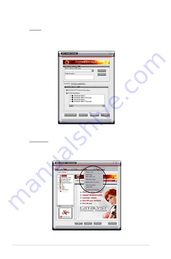
Profiles
Click the
Profiles
tab on the Catalyst™ Control Center to access the Profiles
Manager, which allows you to create customized environments for your
desktop, video, and 3D applications.
Preferences
Click the
Preferences
tab on the Catalyst™ Control Center to select a
language, restore defaults, change skins, or enable/disable the System Tray
icon.


