background image

5-2

Chapter 5: Software support
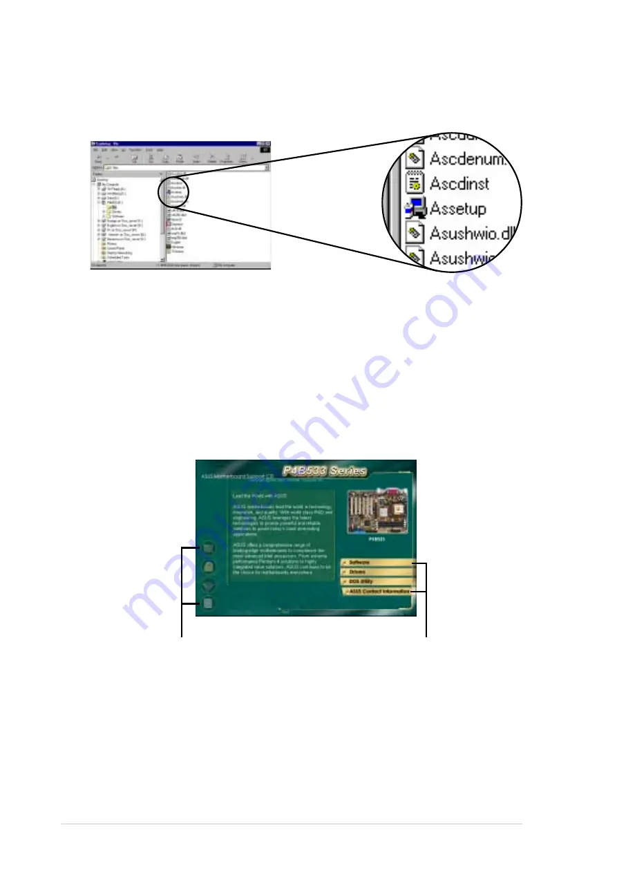
5.2.2 Main menu

From the welcome screen, the program takes you directly to the main
menu. The main menu displays an image of the motherboard, and the
buttons and icons that link you to the software, drivers, utilities, and other
information contained in the support CD.

If the welcome screen did not appear automatically, locate and double-
click on the file ASSETUP.EXE from the BIN folder in the support CD to
display the menus.

Click on a button to display
the available options

Place your mouse cursor
on an icon and click to
display the specified item

Summary of Contents for P4B533

Page 1: ...Motherboard P4B533 V User Guide ...

Page 2: ...OR A PARTICULAR PURPOSE IN NO EVENT SHALL ASUS ITS DIRECTORS OFFICERS EMPLOYEES OR AGENTS BE LIABLE FOR ANY INDIRECT SPECIAL INCIDENTAL OR CONSEQUENTIAL DAMAGES INCLUDING DAMAGES FOR LOSS OF PROFITS LOSS OF BUSINESS LOSS OF USE OR DATA INTERRUPTION OF BUSINESS AND THE LIKE EVEN IF ASUS HAS BEEN ADVISED OF THE POSSIBILITY OF SUCH DAMAGES ARISING FROM ANY DEFECT OR ERROR IN THIS MANUAL OR PRODUCT SP...

Page 3: ...3 2 Value added solutions 1 4 1 4 Motherboard overview 1 6 1 4 1 Major components 1 6 1 4 2 Core specifications 1 8 Chapter 2 Hardware information 2 1 Motherboard installation 2 1 2 1 1 Placement direction 2 1 2 1 2 Screw holes 2 1 2 2 Motherboard layout 2 2 2 3 Before you proceed 2 3 2 4 Central Processing Unit CPU 2 4 2 4 1 Overview 2 4 2 4 2 Installing the CPU 2 5 2 4 3 Installing the heatsink ...

Page 4: ...apter 4 BIOS setup 4 1 Managing and updating your BIOS 4 1 4 1 1 Using ASUS EZ Flash to update the BIOS 4 1 4 1 2 Using AFLASH to update the BIOS 4 3 4 2 BIOS Setup program 4 7 4 2 1 BIOS menu bar 4 8 4 2 2 Legend bar 4 8 4 3 Main Menu 4 10 4 3 1 Primary and Secondary Master Slave 4 12 4 3 2 Keyboard Features 4 16 4 4 Advanced Menu 4 17 4 4 1 Chip Configuration 4 21 4 4 2 I O Device Configuration ...

Page 5: ...menu 5 2 5 2 3 Software menu 5 3 5 2 4 Drivers menu 5 5 5 2 5 DOS Utility menu 5 6 5 2 6 ASUS Contact Information 5 6 5 2 7 Other information 5 7 5 3 Software information 5 9 5 3 1 ASUS Update 5 9 5 3 2 ASUS MyLogo2 5 10 5 3 3 ASUS PC Probe 5 12 5 3 4 E Color 3Deep 5 17 5 3 5 Winbond Voice Editor 5 20 5 3 6 Multi Channel Audio Feature 5 24 Index I 1 ...

Page 6: ... cause harmful interference to radio or television reception which can be determined by turning the equipment off and on the user is encouraged to try to correct the interference by one or more of the following measures Reorient or relocate the receiving antenna Increase the separation between the equipment and receiver Connect the equipment to an outlet on a circuit different from that to which t...

Page 7: ...your area If you are not sure about the voltage of the electrical outlet you are using contact your local power company If the power supply is broken do not try to fix it by yourself Contact a qualified service technician or your retailer Operation safety Before installing the motherboard and adding devices on it carefully read all the manuals that came with the package Before using the product ma...

Page 8: ...e hardware setup procedures that you have to perform when installing system components It includes description of the switches jumpers and connectors on the motherboard Chapter 3 Powering up This chapter describes the power up sequence and gives information on the BIOS beep codes Chapter 4 BIOS setup This chapter tells how to change system settings through the BIOS Setup menus Detailed description...

Page 9: ...are products The ASUS websites are listed in the ASUS Contact Information on page x 2 Optional Documentation Your product package may include optional documentation such as warranty flyers that may have been added by your dealer These documents are not part of the standard package WARNING Information to prevent injury to yourself when trying to complete a task CAUTION Information to prevent damage...

Page 10: ...IONAL America Address 6737 Mowry Avenue Mowry Business Center Building 2 Newark CA 94560 USA General Fax 1 510 608 4555 General Email tmd1 asus com Technical Support Support Fax 1 510 608 4555 General Support 1 502 995 0883 Notebook Support 1 877 918 ASUS 2787 Web Site www asus com Support Email tsd asus com ASUS COMPUTER GmbH Europe Address Harkortstr 25 40880 Ratingen BRD Germany General Fax 49 ...

Page 11: ...X 1 5V only 6 x PCI Integrated in Intel 82845G 2 x UltraDMA 100 66 33 C Media 8738 MX 6 channel PCI audio controller Intel 82562ET PHY ASUS JumperFree mode ASUS POST Reporter ASUS EZ Plug ASUS MyLogo2 ASUS Q Fan ASUS EZ Flash USB 2 0 ready Power Loss Restart SFS Stepless Frequency Selection CPU throttle Adjustable CPU VCORE and memory and AGP voltages Multi language BIOS AGP warning LED LCD TV Out...

Page 12: ... intrusion SMBus and SIR CIR connectors GAME MIDI connector optional S PDIF In Out connector optional CD AUX Modem audio connectors optional Front panel audio connector optional 4Mb Flash ROM Award BIOS TCAV PnP DMI2 0 WfM2 0 SM BIOS2 3 Multi language BIOS ASUS EZ Flash ASUS MyLogo2 PCI 2 2 USB 2 0 WfM 2 0 DMI 2 0 WOL WOR by PME chassis intrusion SMBus ATX form factor 12 in x 9 0 in 30 5 cm x 22 8...

Page 13: ...apter 1 This chapter describes the features of the P4B533 V motherboard It includes brief explanations of the special attributes of the motherboard and the new technology it supports Product introduction ...

Page 14: ...ASUS P4B533 V motherboard Chapter summary 1 1 Welcome 1 1 1 2 Package contents 1 1 1 3 Special features 1 2 1 4 Motherboard overview 1 6 ...

Page 15: ...d 6 channel PCI audio features the P4B533 V is your perfect vehicle to get ahead in the world of power computing Before you start installing the motherboard and hardware devices on it check the items in your package with the list below 1 2 Package contents Check your P4B533 V package for the following items ASUS P4B533 V motherboard ATX form factor 12 in x 9 0 in 30 5 cm x 22 86 cm ASUS P4B533 V s...

Page 16: ...USB 2 0 technology The motherboard implements the new Universal Serial Bus USB 2 0 specification extending the connection speed from 12 Mbps on USB 1 1 to a fast 480 Mbps on USB 2 0 The higher bandwidth of USB 2 0 allows connection of devices such as high resolution video conferencing cameras next generation scanners and printers and fast storage units USB 2 0 is backward compatible with USB 1 1 S...

Page 17: ...ctor from the power supply This connector is necessary to provide the additional power required by the P4 CPU See page 2 27 ASUS POST Reporter P4B533 V offers a new exciting feature called the ASUS POST Reporter to provide friendly voice messages and alerts during the Power On Self Tests POST Through the system s internal speaker or an added external speaker you will hear the messages informing yo...

Page 18: ...ry and processor ASUS Multi language BIOS The multi language BIOS allows you to select the language of your choice from the available options The localized BIOS menus allow you to configure easier and faster Visit the ASUS website for information on the supported languages See page 4 11 on how to select your desired language ASUS EZ Flash BIOS With the ASUS EZ Flash you can easily update the syste...

Page 19: ...p mode or to soft off mode depending on the BIOS setting Pressing the power switch for more than 4 seconds lets the system enter the soft off mode regardless of the BIOS setting ACPI ready The Advanced Configuration power Interface ACPI provides more energy saving features for operating systems that support OS Direct Power Management OSPM Auto fan off The system fans power off automatically when t...

Page 20: ... 2 ATX 12V connector 3 CPU socket 4 North Bridge controller 5 DDR DIMM sockets 6 ASUS EZ Plug 12V connector 7 ATX power connector 8 Floppy disk connector 9 IDE connectors 10 South Bridge controller 11 Super I O controller 12 Standby power LED 13 DIP switches DSW2 14 Flash ROM 15 ASUS ASIC 16 Audio controller optional 17 PCI slots 18 AGP warning LED 19 AGP slot 20 LAN PHY optional 21 PS 2 mouse por...

Page 21: ...ASUS P4B533 V motherboard user guide 1 7 4 5 19 16 2 18 7 8 15 14 17 3 13 1 6 10 11 12 9 20 21 22 31 30 29 27 24 25 26 23 28 ...

Page 22: ...interconnects to the south bridge ICH4 via the Intel proprietary Hub Interface DDR DIMM sockets These three 184 pin DIMM sockets support up to 2GB system memory using unbuffered non ECC PC2100 1600 DDR DIMMs ASUS EZ Plug 12V connector This ASUS patented auxilliary power connector is used if you don t have an ATX 12V power supply Connect a 4 pin device connector from a standard power supply to this...

Page 23: ...inder to turn off the system power before plugging or unplugging devices DIP switches DSW2 This 4 switch Dual Inline Package DIP allows you to select the CPU frequency multiple Flash ROM This 4Mb firmware contains the programmable BIOS program ASUS ASIC This chip performs multiple system functions that include hardware and system voltage monitoring IRQ routing among others Audio controller This C ...

Page 24: ...mode the function of this jack becomes Rear Speaker Out on audio models only Line Out jack This Line Out lime jack connects a headphone or a speaker In 6 channel mode the function of this jack becomes Front Speaker Out on audio models only Microphone jack This Mic pink jack connects a microphone In 6 channel mode the function of this jack becomes Bass Center on audio models only USB 2 0 ports 1 an...

Page 25: ... Hardware information This chapter describes the hardware setup procedures that you have to perform when installing system components It includes details on the switches jumpers and connectors on the motherboard ...

Page 26: ...ter summary 2 1 Motherboard installation 2 1 2 2 Motherboard layout 2 2 2 3 Before you proceed 2 3 2 4 Central Processing Unit CPU 2 4 2 5 System memory 2 10 2 6 Expansion slots 2 13 2 7 Switches and jumpers 2 16 2 8 Connectors 2 24 ...

Page 27: ...1 1 Placement direction When installing the motherboard make sure that you place it into the chassis in the correct orientation The edge with external ports goes to the rear part of the chassis as indicated in the image below 2 1 2 Screw holes Place six 6 screws into the holes indicated by circles to secure the motherboard to the chassis Make sure to unplug the power cord before installing or remo...

Page 28: ...cs Port AGP BCS2 AGP_WARN1 GAME1 SMARTCON1 CLRTC1 C Media CMI8738 6CH Audio Controller SPDIF1 USBPWR_34 KBPWR1 OVER_VOLT1 CHASSIS1 FP_LO_SWL1 USB_56 Super I ODSW2 4Mbit Firmware Hub ASUS ASIC with Hardware Monitor DDR DIMM1 64 72 bit 184 pin module 0 1 Speech Controller DSW1 PS 2KBMS T Mouse B Keyboard DDR DIMM2 64 72 bit 184 pin module 2 3 DDR DIMM3 64 72 bit 184 pin module 4 5 Below Mic In Cente...

Page 29: ... 5 Before you install or remove any component ensure that the ATX power supply is switched off or the power cord is detached from the power supply Failure to do so may cause severe damage to the motherboard peripherals and or components When lit the green LED SB_PWR1 indicates that the system is ON in sleep mode or in soft off mode a reminder that you should shut down the system before removing or...

Page 30: ...res the hyper pipelined technology rapid execution engine 533 400MHz system bus and execution trace cache Together these attributes improve system performance by allowing higher core frequencies faster execution of integer instructions and data transfer rates of 4 2GB s and 3 2GB s Note in the illustration that the CPU has a gold triangular mark on one corner This mark indicates the processor Pin ...

Page 31: ...eps to install a CPU 1 Locate the 478 pin ZIF socket on the motherboard 2 Unlock the socket by pressing the lever sideways then lift it up to a 90 100 angle Make sure that the socket lever is lifted up to 90 100 angle otherwise the CPU does not fit in completely Socket Lever 90 100 ...

Page 32: ... CPU into the socket until it fits in place The CPU fits only in one correct orientation DO NOT force the CPU into the socket to prevent bending the pins and damaging the CPU 5 When the CPU is in place press it firmly on the socket while you push down the socket lever to secure the CPU The lever clicks on the side tab to indicate that it is locked Gold Mark ...

Page 33: ... motherboard components Follow these steps to install the CPU heatsink and fan 1 Place the heatsink on top of the installed CPU making sure that the heatsink fits properly on the retention module base When you buy a boxed Intel Pentium 4 Processor the package includes the heatsink fan and retention mechanism In case you buy a CPU separately make sure that you use only Intel certified heatsink and ...

Page 34: ... the holes on each corner of the module base Keep the retention locks lifted upward while fitting the retention mechanism to the module base Make sure that the fan and retention mechanism assembly perfectly fits the heatsink and module base otherwise you cannot snap the hooks into the holes Retention Hole Retention Hook Snapped to the Retention Hole Retention Lock ...

Page 35: ... to the connector on the motherboard labeled CPU_FAN1 3 Push down the locks on the retention mechanism to secure the heatsink and fan to the module base When secure the retention locks should point to opposite directions Don t forget to connect the CPU fan connector Hardware monitoring errors may occur if you fail to plug this connector CPU Fan Connector CPU_FAN1 ...

Page 36: ...memory however has the ability to perform two data operations in one clock cycle thus providing twice the throughput of SDR memory For example a 200MHz DDR DIMM will support a 100MHz memory bus and a 266MHz DDR DIMM will support a 133MHz memory bus A DDR DIMM has the same physical dimensions as an SDR DIMM but it has a 184 pin footprint compared to the 168 pin of the SDR DIMM Also a DDR DIMM is si...

Page 37: ...e notch on the DIMM matches the break on the socket You may install any DDR DIMMs with 64MB 128MB 256MB 512MB and 1GB densities into the DIMM sockets DDR DIMM1 DDR DIMM2 DDR DIMM3 Rows 0 1 Rows 2 3 Rows 3 2 SS DS DS None SS DS SS SS SS Single sided DIMM DS Double sided DIMM DDR DIMM sockets 2 and 3 share the same rows so if you install a double sided DIMM into DIMM2 socket you must leave DIMM3 soc...

Page 38: ...outward to unlock the DIMM Support the DIMM lightly with your fingers when pressing the retaining clips The DIMM might get damaged when it flips out with extra force 2 Remove the DIMM from the socket 3 Firmly insert the DIMM into the socket until the retaining clips snap back in place and the DIMM is properly seated Locked Retaining Clip ...

Page 39: ...the bracket opposite the slot that you intend to use Keep the screw for later use 4 Align the card connector with the slot and press firmly until the card is completely seated on the slot 5 Secure the card to the chassis with the screw you removed earlier 6 Replace the system cover Make sure to unplug the power cord before adding or removing expansion cards Failure to do so may cause you physical ...

Page 40: ...IDE Channel 15 10 Secondary IDE Channel These IRQs are usually available for ISA or PCI devices When using PCI cards on shared slots ensure that the drivers support Share IRQ or that the cards do not need IRQ assignments Otherwise conflicts will arise between the two PCI groups making the system unstable and the card inoperable IRQ assignments for this motherboard A B C D E F G H PCI slot 1 shared...

Page 41: ... card make sure that you ask for one with 1 5V specification Note the notches on the card golden fingers to ensure that they fit the AGP slot on your motherboard If you installed an incorrect AGP card such as a SiS305 based AGP card or any other 3 3V AGP card the onboard red LED AGP_WARN lights up an indication that the card is not supported on the motherboard As long as this LED is lighted you ca...

Page 42: ...2 3 4 P4B533 V DIP Switches ON OFF DSW2 1 Frequency Selection 2 Frequency Selection 3 Frequency Selection 4 Frequency Selection 5 Frequency Selection 1 Frequency Multiple 2 Frequency Multiple 3 Frequency Multiple 4 Frequency Multiple DSW1 OFF ON ON 1 2 3 4 5 Set the JEN jumper to pins 1 2 jumper mode and the PSBSEL1 jumper to pins 2 3 DSW1 if you wish to use the DSW1 switches Otherwise setting the...

Page 43: ...peed To select the CPU external frequency using the DIP switches ensure that the JEN1 jumper is set to jumper mode P4B533 V DSW1 P4B533 V CPU External Frequency Selection CPU AGP PCI 114MHz 76MHz 38MHz 117MHz 78MHz 39MHz 120MHz 80MHz 40MHz 133MHz 66MHz 33MHz 135MHz 67MHz 33MHz 100MHz 66MHz 33MHz 101MHz 66MHz 33MHz 105MHz 70MHz 35MHz 107MHz 71MHz 35MHz 109MHz 72MHz 36MHz 137MHz 68MHz 34MHz 141MHz 7...

Page 44: ...available only on unlocked CPUs If you are using a locked CPU setting the switches does not produce any effect P4B533 V ON 1 2 3 4 ON 1 2 3 4 ON 1 2 3 4 ON 1 2 3 4 ON 1 2 3 4 ON 1 2 3 4 ON 1 2 3 4 ON 1 2 3 4 ON 1 2 3 4 ON 1 2 3 4 ON 1 2 3 4 ON 1 2 3 4 ON 1 2 3 4 ON 1 2 3 4 ON 1 2 3 4 ON 1 2 3 4 P4B533 V CPU Frequency Multiple Selection DSW2 8 0x 10 0x 11 0x 12 0x 16 0x 15 0x 14 0x 13 0x 17 0x 18 0...

Page 45: ...ontrol 6 VCORE over voltage 3 pin OVER_VOLT1 When enabled this jumper allows CPU VCORE ranges of 1 5V to 1 8V for Pentium 4 Northwood CPU and 1 75V to 1 95V for Pentium 4 Willamette CPU When this jumper is disabled Northwood has a VCORE setting range of 1 5V to 1 7V and Willamette has 1 75V to 1 85V You may adjust the CPU VCORE through the BIOS Setup Setting to a very high core voltage may cause p...

Page 46: ...have the appropriate power supply to support this feature The USBPWR_12 and USBPWR_34 jumpers are for the rear USB ports The USBPWR_56 jumper is for the internal USB header that you can connect to the front USB ports 1 This feature requires a power supply that can provide at least 1A on the 5VSB lead when these jumpers are set to 5VSB Otherwise the system does not power up 2 The total current cons...

Page 47: ... external speaker Connect the speakers to the Line Out jack lime colored on the rear panel 9 SMB V2 0 setting two 3 pin SMB20 These jumpers allow you to enable or disable the SMBus 2 0 support on the motherboard When these jumpers are set to pins 2 3 Enable you may install PCI devices that comply with SMBus 2 0 specification P4B533 V P4B533 V Speaker Selector SPEECH1 LINEOUT BUZZER Default 1 2 2 3...

Page 48: ...ass Center Setting BASS CENTER CENTER BASS BCS1 BCS2 Default 1 2 2 3 11 Line out selector 2 pin FP_LO_SWL1 FP_LO_SWR1 on audio models only By default these jumpers are shorted jumper caps on to route the signal from the audio controller to the rear panel Line Out jack to make it available for audio out devices such as speakers or a headphone If you connect the Intel Front Panel audio cable to the ...

Page 49: ...ation such as system passwords is powered by the onboard button cell battery To erase the RTC RAM 1 Turn OFF the computer and unplug the power cord 2 Remove the battery 3 Short the solder points with a metal object for about 5 seconds 4 Re install the battery 5 Plug the power cord and turn ON the computer 6 Hold down the Del key during the boot process and enter BIOS setup to re enter data P4B533 ...

Page 50: ...LED The read or write activities of any device connected to the primary or secondary IDE connector cause this LED to light up 2 Floppy disk drive connector 34 1 pin FLOPPY1 This connector supports the provided floppy drive ribbon cable After connecting one end to the motherboard connect the other end to the floppy drive Pin 5 is removed to prevent incorrect insertion when using ribbon cables with ...

Page 51: ...the jumper settings BIOS supports specific device bootup If you have more than two UltraDMA 100 66 devices purchase another UltraDMA 100 66 cable You may configure two hard disks to be both master devices with two ribbon cables one for the primary IDE connector and another for the secondary IDE connector 1 Pin 20 on each IDE connector is removed to match the covered hole on the UltraDMA cable conn...

Page 52: ...ith a jumper cap If you wish to use the chassis intrusion detection feature remove the jumper cap from the pins 5 SMBus connector 6 1 pin SMB1 This connector allows you to connect SMBus System Management Bus devices Devices communicate with an SMBus host and or other SMBus devices using the SMBus interface SMBus is a specific implementation of an I2 C bus a multi device bus that allows multiple ch...

Page 53: ... CPU If you are using a standard ATX power supply that does not have the ATX 12V plug connect one 4 pin device power plug to the ASUS EZ Plug connector labeled EZ_PLUG1 Make sure that your ATX 12V power supply can provide 8A on the 12V lead and at least 1A on the 5 volt standby lead 5VSB The minimum recommended wattage is 230W or 300W for a fully configured system The system may become unstable an...

Page 54: ... of sufficient air flow within the system may damage the motherboard components These are not jumpers DO NOT place jumper caps on the fan connectors 8 Smart Card Reader connector 14 1 pin SMARTCON1 optional This connector accommodates a Smart Card Reader that allows you to conveniently make transactions such as financial health care telephony or traveling services through a Smart Card user interfa...

Page 55: ...ame with a USB 2 0 GAME module connect the USB cable to this header The module has two USB 2 0 ports that support the next generation USB peripherals such as high resolution cameras scanners and printers 10 Power supply thermal connector 2 pin TRPWR1 If your power supply has a thermal monitoring feature connect its thermal sensor cable to this connector Download the USB 2 0 driver from the Microso...

Page 56: ...he audio and a voice modem card 11 GAME MIDI connector 16 1 pin GAME1 This connector supports a GAME MIDI module If your package came with the optional USB 2 0 GAME module connect the GAME MIDI cable to this connector The GAME MIDI port on the module connects a joystick or a game pad for playing games and MIDI devices for playing or editing audio files P4B533 V P4B533 V Game Connector GAME1 5V 1 5...

Page 57: ...r 24 1 pin AFPANEL1 optional This connector allows you to connect an optional ASUS iPanel an easy to access drive bay with front I O ports and status LEDs If you are not using an ASUS iPanel you can connect an optional wireless transmitting and receiving infrared module to the SIR connector P4B533 V P4B533 V LINE_IN Connector FP_LINE1 AGND BLINE_LIN_L ALINE_LIN_L BLINE_IN_R LINE_IN_R P4B533 V P4B5...

Page 58: ...connector 10 1 pin FP_AUDIO1 on audio models only This is an interface for the Intel front panel audio cable that allow convenient connection and control of audio devices Make sure to remove the caps from the FP_LO_SWL1 and FP_LO_SWR1 jumpers if you installed the Intel front panel audio cable Refer to page 2 22 for the location of the jumpers P4B533 V P4B533 V Digital Audio Connector SPDIF1 GND 5V...

Page 59: ... P4B533 V Serial COM2 Bracket PIN 1 COM2 18 Serial port 2 connector 10 1 pin COM2 This connector accommodates a second serial port using an optional serial port bracket Connect the bracket cable to this connector then install the bracket into a slot opening at the back of the system chassis System Power LED Lead 3 1 pin PLED This 3 1 pin connector connects to the system power LED The LED lights up...

Page 60: ...his 2 pin connector allows you to manually place the system into a suspend mode or green mode where system activity is instantly decreased to save power and to expand the life of certain system components Attach the case mounted suspend switch to this 2 pin connector ATX Power Switch Soft Off Switch Lead 2 pin PWRBTN This connector connects a switch that controls the system power Pressing the powe...

Page 61: ...Chapter 3 Powering up This chapter describes the power up sequence and gives information on the BIOS beep codes ...

Page 62: ...ASUS P4B533 V motherboard Chapter summary 3 1 Starting up for the first time 3 1 3 2 Vocal POST Messages 3 2 3 3 Powering off the computer 3 4 ...

Page 63: ...en standards or if it has a power standby feature the monitor LED may light up or switch between orange and green after the system LED turns on The system then runs the power on tests While the tests are running the BIOS beeps or additional messages appear on the screen If you do not see anything within 30 seconds from the time you turned on the power the system may have failed a power on test Che...

Page 64: ...el Pentium 4 Processor into the CPU socket System failed CPU test Check the CPU if properly installed Call ASUS technical support for assistance See the ASUS contact information on page x System failed memory test Install 184 pin unbuffered PC2100 1600 DIMMs into the DIMM sockets Check if the DIMMs on the DIMM sockets are properly installed Make sure that your DIMMs are not defective Refer to sect...

Page 65: ...the motherboard See section 2 8 Connectors No IDE hard disk detected Make sure you have connected an IDE hard disk drive to the one of the IDE connectors on the motherboard See section 2 8 Connectors CPU temperature too high Check CPU fan if working properly CPU fan failed Check the CPU fan and make sure it turns on after you applied power to the system CPU voltage out of range Check your power su...

Page 66: ...ou can press the ATX power switch after exiting or shutting down the operating system If you use Windows 95 98 2000 XP click the Start button click Shut Down then click the OK button to shut down the computer The power supply should turn off after Windows shuts down The message You can now safely turn off your computer does not appear when shutting down with ATX power supplies ...

Page 67: ...Chapter 4 BIOS setup This chapter tells how to change system settings through the BIOS Setup menus Detailed descriptions of the BIOS parameters are also provided ...

Page 68: ...S P4B533 V motherboard Chapter summary 4 1 Managing and updating your BIOS 4 1 4 2 BIOS Setup program 4 7 4 3 Main Menu 4 10 4 4 Advanced Menu 4 17 4 5 Power Menu 4 28 4 6 Boot Menu 4 34 4 7 Exit Menu 4 36 ...

Page 69: ...bsite see ASUS contact information on page x Save the file to a floppy disk 2 Reboot the computer 3 To use EZ Flash press Alt F2 during POST to display the following screen Write down the BIOS file name on a piece of paper You need to type the exact BIOS file name at the EZ Flash screen 4 Insert the disk that contains the new BIOS file into the floppy drive You will receive the error message WARNI...

Page 70: ...prompt type Y to continue with the update process Pressing N exits the EZ Flash screen and reboots the system without updating the BIOS The following prompts appear if you typed Y 7 Press Y for both items to completely update the main BIOS area and the boot block area BIOS Information in File BIOS Version P4B533 V Boot Block WARNING Continue to update the BIOS Y N _ DO NOT shutdown or reset the sy...

Page 71: ...O NOT copy AUTOEXEC BAT and CONFIG SYS to the disk 2 Type COPY D AFLASH AFLASH EXE A assuming D is your CD ROM drive to copy AFLASH EXE to the boot disk you created BIOS setup must specify Floppy as the first item in the boot sequence 4 In DOS mode type A AFLASH Enter to run AFLASH If the word unknown appears after Flash Memory the memory chip is either not programmable or is not supported by the ...

Page 72: ...apter 4 BIOS Setup 5 Select 1 Save Current BIOS to File from the Main menu and press Enter The Save Current BIOS To File screen appears 6 Type a filename and the path for example A XXX XX XXX then press Enter ...

Page 73: ...Menu type 2 then press Enter The Update BIOS Including Boot Block and ESCD screen appears 5 Type the filename of your new BIOS and the path for example A XXX XX XXX then press Enter To cancel this operation press Enter 6 When prompted to confirm the BIOS update press Y to start the update Update the BIOS only if you have problems with the motherboard and you are sure that the new BIOS revision wil...

Page 74: ...ge Flashed Successfully appears 8 Follow the onscreen instructions to continue If you encounter problems while updating the new BIOS DO NOT turn off the system because this may cause boot problems Just repeat the process and if the problem persists load the original BIOS file you saved to the boot disk If the Flash Memory Writer utility is not able to successfully update a complete BIOS file the s...

Page 75: ...record them in the CMOS RAM of the Flash ROM The Flash ROM on the motherboard stores the Setup utility When you start up the computer the system provides you with the opportunity to run this program Press Delete during the Power On Self Test POST to enter the Setup utility otherwise POST continues with its test routines If you wish to enter Setup after POST restart the system by pressing Ctrl Alt ...

Page 76: ...ar The keys in the legend bar allow you to navigate through the various setup menus The following table lists the keys found in the legend bar with their corresponding functions Navigation Key s Function Description F1 or Alt H Displays the General Help screen from any where in the BIOS Setup Esc Jumps to the Exit menu or returns to the main menu from a sub menu Left or Right arrow Selects the men...

Page 77: ...p window press Enter or Esc Sub menu Note that a right pointer symbol as shown on the left appears to the left of certain fields This pointer indicates that you can display a sub menu from this field A sub menu contains additional options for a field parameter To display a sub menu move the highlight to the field and press Enter The sub menu appears Use the legend keys to enter values and move fro...

Page 78: ...ay year Valid values for month day and year are Month 1 to 12 Day 1 to 31 Year up to 2099 Use the Tab or Shift Tab keys to move between the month day and year fields Legacy Diskette A 1 44M 3 5 in Sets the type of floppy drive installed Configuration options None 360K 5 25 in 1 2M 5 25 in 720K 3 5 in 1 44M 3 5 in 2 88M 3 5 in Floppy 3 Mode Support Disabled This is required to support older Japanes...

Page 79: ...ring system startup Passwords are not case sensitive meaning passwords typed in either uppercase or lowercase letters are accepted The BIOS Setup program allows you to specify two different passwords a Supervisor password and a User password If you did not set a Supervisor password anyone can access the BIOS Setup program If you did the Supervisor password is required to enter the BIOS Setup progr...

Page 80: ... be because the hard disk drive is too old or too new If the hard disk was already formatted on an older system Setup may detect incorrect parameters In these cases select User Type HDD to manually enter the IDE hard disk drive parameters Refer to the next section for details Before attempting to configure a hard disk drive make sure you have the correct configuration information supplied by the d...

Page 81: ...ess the Esc key to return to the Main menu When the Main menu appears the hard disk drive field displays the size for the hard disk drive that you configured User Type HDD After entering the IDE hard disk drive information into BIOS use a disk utility such as FDISK to partition and format new IDE hard disk drives This is necessary so that you can write or read data from the hard disk Make sure to ...

Page 82: ...the Translation Method field to Manual Head This field configures the number of read write heads Refer to the drive documentation to determine the correct value To make changes to this field set the Type field to User Type HDD and the Translation Method field to Manual Sector This field configures the number of sectors per track Refer to the drive documentation to determine the correct value To ma...

Page 83: ...toring Disabled This field allows you to enable or disable the S M A R T Self Monitoring Analysis and Reporting Technology system that utilizes internal hard disk drive monitoring technology This parameter is normally disabled because the resources used in the SMART monitoring feature may decrease system performance Configuration options Disabled Enabled PIO Mode 4 This option lets you set a PIO P...

Page 84: ...rd Auto Repeat Rate 6 Sec This controls the speed at which the system registers repeated keystrokes Options range from 6 to 30 characters per second Configuration options 6 Sec 8 Sec 10 Sec 12 Sec 15 Sec 20 Sec 24 Sec 30 Sec Keyboard Auto Repeat Delay 1 4 Sec This field sets the time interval for displaying the first and second characters Configuration options 1 4 Sec 1 2 Sec 3 4 Sec 1 Sec ...

Page 85: ...et to Manual This field sets the frequency multiple between the CPU s internal frequency CPU speed and external frequency Set this field in conjunction with CPU Frequency MHz to match the speed of the CPU The item CPU Frequency Multiple is accessible only if you have an unlocked processor If your processor frequency multiple is locked you cannot change the setting of this item CPU External Frequen...

Page 86: ...the AGP PCI frequency If the system becomes unstable return to the default setting Auto When this item is set to Manual the AGP PCI Frequency MHz item appears Configuration options Auto Manual Selecting a very high AGP PCI frequency may cause the system to be unstable CPU VCore Setting Auto The Manual setting allows you to manually select the core voltage supplied to the CPU see next item However ...

Page 87: ...following table DDR Reference Voltage Auto This item controls the DDR SDRAM operating voltage Configuration options 2 9V 2 7V 2 6V Auto AGP VDDQ Voltage Auto This item controls the AGP operating voltage Configuration options 1 7V 1 6V 1 5V Auto CPU Level 1 Cache CPU Level 2 Cache Enabled These fields allow you to choose from the default Enabled or choose Disabled to turn on or off the CPU Level 1 ...

Page 88: ...RQ12 whether or not a PS 2 mouse is detected at startup Configuration options Enabled Auto USB Legacy Support Auto This motherboard supports Universal Serial Bus USB devices The default of Auto allows the system to detect a USB device at startup If detected the USB controller legacy mode is enabled If not detected the USB controller legacy mode is disabled When you set this field to Disabled the U...

Page 89: ... depends on SDRAM SPD This item controls the latency between the DDR SDRAM active command and the read write command Configuration options 2T 3T SDRAM Configuration By SPD This parameter allows you to set the optimal timings for items 2 5 depending on the memory modules that you are using The default setting is By SPD which configures items 2 5 by reading the contents in the SPD Serial Presence De...

Page 90: ...led to enable the onboard VGA controller Set to Auto to allow BIOS to automatically select either the onboard VGA or the AGP card controller if you installed one The AGP card cannot be selected if this field is set to Enabled Configuration options Auto Enabled Graphics Aperture Size 64MB This feature allows you to select the size of mapped memory for AGP graphic data Configuration options 4MB 8MB ...

Page 91: ...ystem components Expansion cards can only access memory up to 16MB Configuration options Disabled Enabled Delayed Transaction Disabled When set to Enabled this feature frees the PCI bus when the CPU is accessing 8 bit ISA cards This process normally consumes about 50 60 PCI clocks without PCI delayed transaction Set this field to Disabled when using ISA cards that are not PCI 2 1 compliant Configu...

Page 92: ...allow you to set the addresses for the onboard serial connectors Serial Port 1 and Serial Port 2 must have different addresses Configuration options 3F8H IRQ4 2F8H IRQ3 3E8H IRQ4 2E8H IRQ10 Disabled UART2 Use As COM Port This field allows you to select the device on which to assign UART2 Configuration options COM Port IR Smart Card Reader Onboard Parallel Port 378H IRQ7 This field allows you to se...

Page 93: ...llows normal speed operation in a two way mode Configuration options Normal EPP ECP ECP EPP ECP DMA Select 3 This field allows you to configure the parallel port DMA channel for the selected ECP mode This selection is available only if you select ECP or ECP EPP in Parallel Port Mode above Configuration options 1 3 Speech POST Reporter Enabled This field enables or disables the ASUS POST Reporter f...

Page 94: ... like graphics accelerators or MPEG video cards may not show colors properly Setting this field to Enabled corrects this problem If you are using standard VGA cards leave this field to the default setting Disabled Configuration options Disabled Enabled PCI Latency Timer 32 Leave this field to the default setting 32 for best performance and stability USB 1 1 Controllers 3 Controllers This field all...

Page 95: ...ions No ICU Yes 4 4 3 1 PCI IRQ Resource Exclusion USB 2 0 Controller Enabled This field allows you to enable or disable the onboard USB 2 0 controller Set to Enabled if you wish to install USB 2 0 devices Configuration options Disabled Enabled Primary VGA BIOS PCI VGA Card This field allows you to select the primary graphics card Configuration options PCI VGA Card AGP VGA Card Onboard LAN Control...

Page 96: ...Saving system power is conserved to its greatest amount This setting automatically puts the system into suspend mode after a brief period of system inactivity Min Saving allows the least power saving as the system enters suspend mode only after a long period of inactivity Configuration options User Defined Disabled Min Saving Max Saving You should install the Advanced Power Management APM utility ...

Page 97: ... any IDE hard disk drives in the system after a period of inactivity as set in this user configurable field This feature does not affect SCSI hard drives Configuration options Disabled 1 Min 2 Min 3 Min 15 Min ACPI Suspend To RAM Disabled This field allows you to enable or disable the ACPI Suspend to RAM feature To support this feature the 5VSB of the power supply should have the capacity to provi...

Page 98: ...up the computer when the external modem receives a call while the computer is in Soft off mode Configuration options Disabled Enabled The computer cannot receive or transmit data until the computer and applications are fully running Thus connection cannot be made on the first try Turning an external modem off and then back on while the computer is off causes an initialization string that turns the...

Page 99: ... On By PS 2 Mouse Disabled When set to Enabled this parameter allows you to use the PS 2 mouse to turn on the system This feature requires an ATX power supply that provides at least 1A on the 5VSB lead Configuration options Disabled Enabled Automatic Power Up Disabled This allows an unattended or automatic system power up You may configure your system to power up at a certain time of the day by se...

Page 100: ...perature see page 2 29 for the location of the TRPWR connector The POWER temperature item shows N A if you do not have the appropriate power supply Select Ignore to disable the power temperature auto detect function Q Fan Control Disabled This item allows you to enable or disable the ASUS Q Fan feature that smartly adjusts the fan speeds for more efficient system operation When this field is set t...

Page 101: ...ons 10 15 11 15 12 15 13 15 14 15 Full Speed Speed Up Down Response Time 4 Sec 8 Sec This item indicates the time period before the fan speeds adjust to the value set in the Fan Speed Ratio field This item appears only when the Q Fan Control item is set to Enabled Configuration options 1 Sec 2 Sec 2 Sec 4 Sec 3 Sec 6 Sec 4 Sec 8 Sec CPU Fan Speed xxxxRPM or N A Chassis Fan Speed xxxxRPM or N A Pow...

Page 102: ...ard Drive ATAPI CD ROM and Other Boot Device Removable Device Legacy Floppy Configuration options Disabled Legacy Floppy LS 120 ZIP ATAPI MO IDE Hard Drive This field allows you to select which IDE hard disk drive to use in the boot sequence Pressing Enter will show the product IDs of all connected IDE hard disk drives ATAPI CD ROM This field allows you to select which ATAPI CD ROM drive to use in...

Page 103: ...message when it detects a virus If this occurs you can either allow the operation to continue or use a virus free bootable floppy disk to restart and investigate your system Configuration options Disabled Enabled Quick Power On Self Test Enabled This field speeds up the Power On Self Test POST routine by skipping retesting a second third and fourth time Configuration options Disabled Enabled Boot ...

Page 104: ...ff When you select this option a confirmation window appears Select Yes to save changes and exit Pressing Esc does not immediately exit this menu Select one of the options from this menu or F10 from the legend bar to exit If you attempt to exit the Setup program without saving your changes the program prompts you with a message asking if you want to save your changes before exiting Pressing Enter ...

Page 105: ...ing the values to the non volatile RAM Discard Changes This option allows you to discard the selections you made and restore the previously saved values After selecting this option a confirmation appears Select Yes to discard any changes and load the previously saved values Save Changes This option saves your selections without exiting the Setup program You can then return to other menus and make ...

Page 106: ...4 38 Chapter 4 BIOS Setup ...

Page 107: ...Chapter 5 Software support This chapter describes the contents of the support CD that comes with the motherboard package ...

Page 108: ...ASUS P4B533 V motherboard Chapter summary 5 1 Install an operating system 5 1 5 2 Support CD information 5 1 5 3 Software information 5 9 ...

Page 109: ...or general reference only Refer to your OS documentation for more information 5 2 Support CD information The support CD that came with the motherboard contains useful software and several utility drivers that enhance the motherboard features 5 2 1 Running the support CD To begin using the support CD simply insert the CD into your CD ROM drive The CD automatically displays the welcome screen and th...

Page 110: ...d icons that link you to the software drivers utilities and other information contained in the support CD If the welcome screen did not appear automatically locate and double click on the file ASSETUP EXE from the BIN folder in the support CD to display the menus Click on a button to display the available options Place your mouse cursor on an icon and click to display the specified item ...

Page 111: ...n to display the second menu screen To return to the first menu screen click on the Back button on the lower right corner of the second screen ASUS Update This program allows you to download the latest version of the BIOS from the ASUS website Before using the ASUS Update make sure that you have an Internet connection so you can connect to the ASUS website ASUS Screen Saver This item installs the ...

Page 112: ...eoLive Mail 4 0 Direct X This item installs the Microsoft V8 0a driver E Color 3Deep This item installs the 3Deep software 3Deep is the first application that gives online gamers the competitive edge in multi player skirmishes This application removes dark washed out graphics to deliver true vibrant colors Acrobat Reader This item installs the Adobe Acrobat Reader V5 0 The Acrobat Reader software ...

Page 113: ... components This utility installs to the target system the Windows INF files that outline to the operating system how the chipset components will be configured You may install this utility in three modes interactive silent and unattended preload The interactive mode requires user input during installation This is not required in the silent and unattended preload modes Refer to the online help or r...

Page 114: ...DOS version You can use this utility if you wish to update the BIOS Audio utility This item installs the C Media audio controller Smart Card Reader This item installs the Smart Card Reader device driver AGP This item installs the AGP driver USB2 The Microsoft USB 2 0 driver has not been officially released as of the support CD production date Please download the USB 2 0 driver from the Microsoft w...

Page 115: ...ional information on the motherboard and the contents of the support CD This section shows the pop up windows that appear when you click the icons Motherboard Info The window displays the general specifications of the P4B533 V motherboard Browse this CD The window displays the support CD contents in graphical format ...

Page 116: ...al Support Form The window displays the ASUS Technical Support Request Form that you have to fill up when requesting technical support Readme The window displays the contents of the support CD and a brief description of each in text format ...

Page 117: ...te The ASUS Update is a utility that allows you to update the motherboard BIOS and drivers This utility requires an Internet connection either through a network or an Internet Service Provider ISP Follow these steps to use the ASUS Update 2 Select your desired update method then click Next 1 Launch the utility from your Windows Start menu Programs AsusUpdate Vx xx xx AsusUpdate The ASUS Update ini...

Page 118: ...atically installed when you install the ASUS Update utility from the software menu See section 5 2 3 Software menu 1 Launch the ASUS Update utility See section 5 3 1 ASUS Update 2 When prompted for the BIOS update method select the option Update BIOS from a file 3 Specify the location of the BIOS file such as from a floppy disk Click Next Before using ASUS MyLogo2 feature use the AFLASH utility to...

Page 119: ...ASUS MyLogo2 directly from the Windows Start menu to change your BIOS boot logo After you have modified the BIOS file with the new logo use the ASUS Update utility to upload the new BIOS into the EEPROM 4 From the selection that appears choose a logo image Click Next 5 When you click on an image it displays larger on the MyLogo2 screen If you wish you may create your own boot logo image in GIF JPG...

Page 120: ...nal external frequencies through the DMI Explorer Starting ASUS PC Probe When ASUS PC Probe starts a splash screen appears allowing you to select whether to show the screen again when you open PC Probe or not To bypass this startup screen clear the Show up in next execution check box The PC Probe icon appears on the taskbar system tray indicating that ASUS PC Probe is running Clicking the icon all...

Page 121: ...mperature for supported processors only Temperature Warning threshold adjustment Move the slider up to increase the threshold level or down to decrease the threshold level Fan Monitor Shows the PC fan rotation Voltage Monitor Shows the PC voltages Fan Warning threshold adjustment Move the slider up to increase the threshold level or down to decrease the threshold level ...

Page 122: ...ws the used and free space of the PC s hard disk drives and the file allocation table or file system used Fan Control Lets you enable disable Smart Fan Control Smart Fan Control adjusts the fan speed automatically based on the current CPU temperature and predefined threshold CPU Cooling System Setup Lets you select when to enable software CPU cooling When When CPU Overheated is selected the CPU co...

Page 123: ...mation pertinent to the PC such as CPU type CPU speed and internal external frequencies and memory size Utility Lets you run programs outside of the ASUS Probe modules To run a program click Execute Program NOTE This feature is currently unavailable Information Memory Shows the PC memory load memory usage and paging file usage ...

Page 124: ...king the PC Probe icon brings up a menu to open or exit ASUS PC Probe and pause or resume all system monitoring When the ASUS PC Probe senses a problem with your PC portions of the ASUS PC Probe icon change to red the PC speaker beeps and the ASUS PC Probe monitor appears ...

Page 125: ...may also tune your internet applications to match true internet source colors with the color displayed on the monitor 3Deep Control Panel Using the Windows Start button activate the 3Deep Control Panel program from the 3Deep Applications group on the Main Program menu The control panel offers access to the Color Wizard tuning program a Game Gamma setting and a Tweak slider for brightness adjustmen...

Page 126: ...sely blend and match with the background 2 Follow the instructions to manually adjust the brightness level of the monitor 3 Select the faintest of the three colors blue red and green 3Deep Color Tuning 1 Select the type of monitor connected to the computer either CRT or LCD ...

Page 127: ...ars indicating that the tuning process is complete click Finish 5 The next step repeats the color matching process to achieve full color quality 7 Click on the Set Up Now button to connect to the Internet Follow the screen instructions to set up True Internet Color ...

Page 128: ...rogram Launch the program either from the Winbond Voice Editor icon on your desktop or from the Windows Start menu Programs Winbond Voice Editor Voice Editor The Winbond Voice Editor screen appears Playing the default wave files To play the default wave files simply click on a POST event on the left side of the screen then click the Play button The default language setting is English To avoid conf...

Page 129: ...ick Open The event messages for the language you selected appear on the Voice Editor screen For some languages not all events have a corresponding message due to file size constraints 3 Click on the Write button to update the EEPROM 4 Click Yes on the confirmation window that appears The next time you boot your computer the POST messages are announced in the language that you selected ...

Page 130: ... POST events on the leftmost column of the screen 2 Prepare your message for each event The total compressed size for all the wave files must not exceed 1Mbit so make your messages as short as possible 3 Use a recording software such as Windows Recorder to record your messages 4 Save the messages as wave files WAV It is recommended that you save your files in low quality to keep them small For exa...

Page 131: ...en on the Edit button The Event Sound Editor window appears 8 Locate and select your wave file for the event then click on the arrow opposite Voice1 The file you selected appears on the space next to it 9 Click OK to return to the Voice Editor screen 10 Do steps 7 to 9 for the other events 11 When done click the Save button A window appears prompting you to save your configuration 12 Type a file n...

Page 132: ...s Mixer Audio Rack 3 Click on the mixer icon to display the C Media Audio Mixer 4 Click on the Advanced button on the Mixer to display the Speaker Volume Sound Effects and Options menus Make sure that the BCS1 BCS2 jumpers are set correctly before using the 6 channel audio feature See page 2 22 for the settings You must use 4 or 6 channel speakers for this setup Setting the C Media Audio Mixer 1 I...

Page 133: ...for configuring and testing your speaker system To configure your speakers launch the Speaker Channel Configuration menu by clicking on the TV Box on the program interface The functions of the Line Out lime Line In blue and Mic pink connectors on the rear panel change when you select the 6 channel audio configuration Refer to the following table Connector Settings and Functions Headphone 2 Speaker...

Page 134: ...5 26 Chapter 5 Software support ...

Page 135: ...Index This part contains an alphabetical list of the topics found in this document ...

Page 136: ...ASUS P4B533 V motherboard ...

Page 137: ...ng 4 1 BIOS Beep Codes 3 1 BIOS AFLASH utility 4 3 Boot Device selection 4 35 Boot Up NumLock Status 4 16 Boot Virus Detection 4 35 C Central Processing Unit CPU fan connector 2 9 installation 2 5 Level 1 Level 2 Cache 4 19 Speed 4 17 CPU socket 1 8 2 5 Chip Configuration 4 21 Clear RTC RAM 2 23 Concurrent PCI 1 4 Connectors ASUS EZ Plug 1 3 1 8 2 27 ASUS iPanel 2 31 ATX power 1 6 2 27 chassis ala...

Page 138: ...J JumperFree mode 2 16 Jumpers Bass Center setting 2 22 Clear RTC 2 23 CPU sysstem bus 2 17 JumperFree 2 16 keyboard power 2 19 Line Out selector 2 22 SMBus 2 0 2 21 Speaker selector 2 21 USB device wake up 2 20 VCORE over voltage 2 19 K Keyboard Auto Repeat Delay 4 16 Auto Repeat Rate 4 16 L LEDs AGP warning 1 9 2 3 standby power 1 9 2 3 Legacy Diskette 4 10 M Motherboard major components 1 6 IRQ...

Page 139: ...Monitoring 4 15 Sony Philips Digital Interface S PDIF 1 3 2 32 Super I O controller 1 9 Support CD 5 1 ASUS Update 5 9 DOS Utility menu 5 6 Drivers menu 5 5 E Color 3Deep 5 17 Main menu 5 2 motherboard information 5 7 multi channel audio 5 24 readme file 5 8 Software menu 5 3 Technical Support Form 5 8 Welcome screen 5 1 Suspend Mode 4 29 System Controller North Bridge 1 8 South Bridge 1 8 System ...

Page 140: ...I 4 Index ...

Reviews: