


28
ASUS P2B-L/P2B-S/P2B-LS User’s Manual
Connectors
III. INST
ALLA
TION
III. INSTALLATION
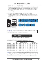
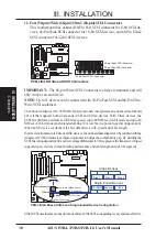
6. Universal Serial BUS Ports 1 & 2 (Two 4-pin Female)
Two USB ports are available for connecting USB devices.
P2B-L/S/LS Universal Serial Bus (USB)
USB 2
USB 1
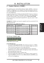
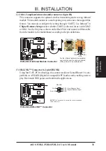
7. LAN Condition Connector (6-pin A) (optional/reserved)
This connector supports the optional network condition connector module. This
module mounts to system cases that support this feature.
R
P2B-L/S/LS Network Condition LED Connectors
Link LED Connector
Activity LED Connector
Speed LED Connector
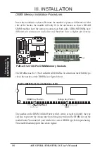
8. Floppy Disk Drive Connector (34-1pin FLOPPY)
This connector supports the provided floppy disk drive ribbon cable. After con-
necting the single end to the board, connect the two plugs on the other end to the
floppy drives. (Pin 5 is removed to prevent inserting in the wrong orienta-
tion when using ribbon cables with pin 5 plugged.)
R
P2B-L/S/LS Floppy Disk Drive Connector
NOTE: Orient the red stripe to Pin 1
Floppy Drive Connector
Pin 1
Summary of Contents for P2B-L
Page 8: ......
Page 16: ...16 ASUS P2B L P2B S P2B LS User s Manual This page was intentionally left blank ...
Page 32: ......
Page 46: ......
Page 78: ...78 ASUS P2B L P2B S P2B LS User s Manual This page was intentionally left blank ...
Page 87: ...ASUS P2B L P2B S P2B LS User s Manual 87 This page was intentionally left blank ...
Page 88: ...88 ASUS P2B L P2B S P2B LS User s Manual This page was intentionally left blank ...


