background image

10

ASUS P/I-XP55T2P4 User’s Manual

III. INSTALLATION

(Jumpers)

III.  INST

ALLA

TION

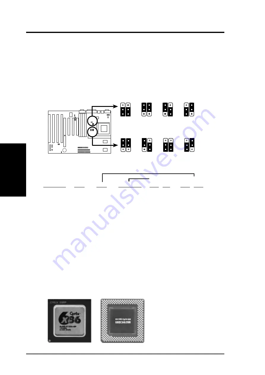
7. CPU External Clock (BUS) Frequency Selection  (JP9, JP10)

These jumpers tells the clock generator what frequency to send to the CPU to allow
the selection of the CPU’s External frequency (or BUS Clock).  The BUS Clock
times the BUS Ratio equals the CPU's Internal frequency (the advertised CPU speed).

8. CPU to BUS Frequency Ratio  (JP12, JP13)

These jumpers set the frequency ratio between the Internal frequency of the CPU
and the External frequency (called the BUS Clock) within the CPU.  These must
be set together with the above jumpers CPU External (BUS) Frequency Selection.

1
2
3

JP9

50MHz

55MHz

1
2
3

60MHz

1
2
3

66MHz

1
2
3

CPU External Clock (BUS) Frequency Selection

CPU : BUS Frequency Ratio (1.5x, 2.0x, 2.5x, 3.0x)

JP10

1.5 x

2.0 x

2.5 x

3.0 x

JP9

JP10

JP9

JP10

JP9

JP10

1
2
3

1
2
3

1
2
3

1
2
3

JP12

JP13

JP12

JP13

JP12

JP13

JP12

JP13

Set the jumpers by the Internal speed of the 

Intel, AMD, or Cyrix 

CPU’s as follows:

(BUS Freq.)

(Freq. Ratio)

CPU Model

Freq.

Ratio

(BUS Freq.)

JP10 JP9

JP13 JP12

Intel Pentium

200MHz

3.0x

66MHz

[2-3] [1-2]

[2-3] [1-2]

Intel Pentium

166MHz

2.5x

66MHz

[2-3] [1-2]

[2-3] [2-3]

Intel Pentium

150MHz

2.5x

60MHz

[1-2] [2-3]

[2-3] [2-3]

Intel Pentium

133MHz

2.0x

66MHz

[2-3] [1-2]

[1-2] [2-3]

Intel Pentium

120MHz

2.0x

60MHz

[1-2] [2-3]

[1-2] [2-3]

Intel Pentium

100MHz

1.5x

66MHz

[2-3] [1-2]

[1-2] [1-2]

Intel Pentium

90MHz

1.5x

60MHz

[1-2] [2-3]

[1-2] [1-2]

Intel Pentium

75MHz

1.5x

50MHz

[2-3] [2-3]

[1-2] [1-2]

AMD

100MHz

1.5x

66MHz

[2-3] [1-2]

[1-2] [1-2]

AMD

90MHz

1.5x

60MHz

[1-2] [2-3]

[1-2] [1-2]

AMD

75MHz

1.5x

50MHz

[2-3] [2-3]

[1-2] [1-2]

*Cyrix 166+

133MHz

2.0x

66MHz

[2-3] [1-2]

[1-2] [2-3]

*The only Cyrix CPU that is supported on this motherboard is labeled Cyrix 6x86
P166+ but must be Revision 2.7 and later.  Look on the underside of the CPU for the
serial number.  The number should read G8DC6620A or larger.

Summary of Contents for P/I-XP55T2P4

Page 1: ...R P I XP55T2P4 Pentium Motherboard USER S MANUAL ...

Page 2: ...s of use or data interruption of business or for indirect special incidental or consequential damages of any kind even ifASUS has been advised of the possibility of such damages arising from any defect or error in this manual or product ASUS may revise this manual from time to time without notice Products mentioned in this manual are mentioned for identification purposes only Product names appeari...

Page 3: ...s com tw Gopher gopher asus com tw FTP ftp asus com tw pub ASUS ASUS COMPUTER INTERNATIONAL Marketing Info Address 721 Charcot Avenue San Jose CA 95131 USA Telephone 1 408 474 0567 Fax 1 408 474 0568 Email info usa asus com tw Technical Support BBS 1 408 474 0569 Email tsd usa asus com tw ASUS COMPUTER GmbH Marketing Info Address Harkort Str 25 40880 Ratingen BRD Germany Telephone 49 2102 445011 F...

Page 4: ... SRAM 12 TAG SRAM Upgrade 12 DRAM Memory Installation Procedures 13 Static RAM SRAM for Level 2 External Cache 14 Compatible Cache Modules for this Motherboard 14 3 Central Processing Unit CPU 15 4 Expansion Cards 16 Expansion Card Installation Procedure 16 Assigning IRQs for Expansion Cards 16 Assigning DMA Channels for ISA Cards 17 ASUS MediaBus Card 18 5 External Connectors 19 Power Connection ...

Page 5: ...KTOP MANAGEMENT 49 Desktop Management Interface DMI 49 Introducing the DMI Configuration Utility 49 System Requirements 49 Using the DMI Configuration Utility 50 Notes 50 VI PCI SC200 SCSI Card 53 NCR SCSI BIOS and Drivers 53 The PCI SC200 SCSI Interface Card 54 Setting Up the PCI SC200 54 Setting the INT Assignment 55 Terminator Settings 55 SCSI ID Numbers 56 VII I A16C Audio Card 57 I A16C Audio...

Page 6: ...icular installation If this equipment does cause harmful interference to radio or television reception which can be determined by turning the equipment off and on the user is encouraged to try to correct the inter ference by one or more of the following measures Re orient or relocate the receiving antenna Increase the separation between the equipment and receiver Connect the equipment to an outlet...

Page 7: ...II DOS Win3 1x Audio Software Manual with I A16C bundle only IX Windows 95 Audio Software Manual with I A16C bundle only Item Checklist Please check that your package is complete If you discover damaged or missing items please contact your retailer The ASUS P I XP55T2P4 motherboard with built in 2 serial 1 parallel PS 2 Keyboard and PS 2 Mouse connectors 1 IDE ribbon cable 1 floppy ribbon cable Su...

Page 8: ...able to 512KB or 512KB onboard Pipelined Burst SRAM Upgrades are made through a Synchronous SRAM cache module See page 14 for compatible cache modules Versatile DRAM Memory Support Supports 72 pin SIMMs of 4MB 8MB 16MB 32MB or 64MB to form a memory size between 8MB to 256MB Supports both Fast Page Mode FPM and Extended Data Output EDO SIMMs see page 12 ISA and PCI Expansion Slots Provides four 16 ...

Page 9: ...odes 3 and 4 and Bus Master IDE DMA Mode 2 BIOS supports IDE CD ROM or SCSI boot up Optional IrDA This motherboard supports an optional infrared port module for wireless interface Parts of the Motherboard II FEATURES Parts of Board Intel s 430HX PCIset Onboard 256KB 512KB Pipelined Burst L2 Cache CPU ZIF Socket 7 PCI 4 or ASUS MediaBus 2 0 Super Multi I O Programmable Flash ROM 4 72 pin SIMM Socke...

Page 10: ... Mouse PS 2 Key board Parallel Printer COM 2 Case Connector JP17 JP18 CPU ZIF Socket 7 Tag SRAM Upgrade IR Conn MediaBus 2 0 PCI Slot 2 PCI Slot 4 Secondary IDE Primary IDE PCI Slot 3 CMOS Operate Clear Block Write Dis En JP19 JP16 Multi I O En Dis Universal Serial Bus Super Multi I O JP12 L2 Cache 256 512 JP15 JP14 JP13 Memory Cached 64 512 CPU Fan Power Bus Freq JP9 JP10 Freq Ratio CPU Volt STD ...

Page 11: ...p 16 16 bit ISA Bus Expansion slots 6 PCI Slots 1 2 3 p 16 32 bit PCI Bus Expansion slots 7 PCI 4 MediaBus p 18 32 bit PCI Bus Slot and MediaBus Connectors 1 PS 2 Keyboard p 19 PS 2 Keyboard connector 6 pin female 2 PS 2 Mouse p 19 PS 2 Mouse connector 6 pin female 3 Parallel Port p 19 Parallel Port connector 25 pin female 4 Serial Port p 19 Serial Port COM1 COM2 9 pin male 5 ATX Power Input p 20 ...

Page 12: ...also be shown graphically such as to connect pins 1 2 and to connect pins 2 3 Jumpers with two pins will be shown as for short On and for open Off For manufacturing simplicity the jumpers may be sharing pins from other groups Use the diagrams in this manual instead of following the pin layout on the board Settings with two jumper numbers require that both jumpers be moved together To connect the p...

Page 13: ...che you may install a cache module of either 256KB or 512KB IMPORTANT See page 14 SRAM Cache for installation procedures Regardless of your cache combination set the following jumpers according to the total amount of L2 cache that is present onboard and installed as a module Cache Size JP14 256KB 1 2 512KB 2 3 Total L2 Cache Size Setting 256KB 512KB JP14 256KB 512KB 1 2 3 JP14 1 2 3 2 Flash ROM Bo...

Page 14: ...t to 64MB 512MB will make the system unstable Mcache chips can only allow cacheable memory up to 64MB See Map of Motherboard on page 4 for L2 cache locations If the cache module that you install already have an extended tag do not install another TAG SRAM into the TAG SRAM Upgrade Socket Cacheable Size JP15 64MB BSRAM MCache 1 2 Default 512MB BSRAM Only 2 3 Memory Cacheable Size 64MB 512MB 512MB C...

Page 15: ...2 Default Clear CMOS Data 2 3 momentarily CMOS RAM Operation Clear CMOS Data Operation Default Clear CMOS Data JP17 1 2 3 JP17 1 2 3 6 Battery Test Jumper JP19 The CMOS RAM is powered by the onboard button cell battery You can test the battery s current by removing this jumper and attaching a current meter to each pin WARNING You must unplug the power cord to your power supply to ensure that there...

Page 16: ...JP9 JP10 JP9 JP10 JP9 JP10 1 2 3 1 2 3 1 2 3 1 2 3 JP12 JP13 JP12 JP13 JP12 JP13 JP12 JP13 Set the jumpers by the Internal speed of the Intel AMD or Cyrix CPU s as follows BUS Freq Freq Ratio CPU Model Freq Ratio BUS Freq JP10 JP9 JP13 JP12 Intel Pentium 200MHz 3 0x 66MHz 2 3 1 2 2 3 1 2 Intel Pentium 166MHz 2 5x 66MHz 2 3 1 2 2 3 2 3 Intel Pentium 150MHz 2 5x 60MHz 1 2 2 3 2 3 2 3 Intel Pentium 1...

Page 17: ...CPU s For ex ample most CPU s only have a single power plane and use the standard voltage settingbutcurrentlyCyrix6x86166 Rev2 7 AMDK586 100 andIntelPentium 166 200 CPU s use the VRE setting WARNING You can damage your CPU if you are not exactly clear on CPU jumper settings check with your retailer before using your system Single Power Plane JP1 STD 3 3V 3 465V 1 2 Default VRE 3 4V 3 6V 2 3 Voltag...

Page 18: ...ule Modules with more than 24 chips exceed the design specifications of the memory sub system and will cause unreliable operation TAG SRAM Upgrade The purpose of this SRAM is described on page 9 You must use a standard 5Volt SRAM chip that is 15ns or faster See the illustration below for installation location and orientation Insert one 16K8 or 32K8 SRAM chip as shown by the Top view with the semi ...

Page 19: ...dule firmly into place starting from a 45 degree angle making sure that all the contacts are aligned with the sockets 3 With your finger tips rock the memory module into a vertical position so that it clicks into place Metal Clip Plastic Safety Tab This Side Only Mounting Hole 72 Pin DRAM in SIMM Socket 4 The plastic guides should go through the two Mounting Holes on the sides and the Metal Clips ...

Page 20: ...umper 1 Total Level 2 Cache Size Setting on page 8 when changes are made to your cache size Pipelined Burst Cache Module 42 Pins 38 Pins Insert the module as shown Because the number of pins are different on either side of the break the module will only fit in the orientation as shown Compatible Cache Modules for this Motherboard NOTE ASUS CMI Rev 3 0 has two TAG SRAM s to comply with COAST 3 0 sp...

Page 21: ...rt the CPU with the correct orientation as shown Use the notched corner of the CPU with the white dot as your guide The white dot should point towards the end the of the lever Notice that there is a blank area where one hole is missing from that corner of the square array of pin holes and a 1 printed on the motherboard next to that corner Because the CPU has a corner pin for three of the four corn...

Page 22: ...n your expansion card 3 Remove your computer system s cover 4 Remove the bracket on the slot you intend to use Keep the bracket for pos sible future use 5 Carefully align the card s connectors and press firmly 6 Secure the card on the slot with the screw you removed in step 4 7 Replace the computer system s cover 8 Setup the BIOS if necessary such as IRQ xx Used By ISA Yes in PNPAND PCI SETUP 9 In...

Page 23: ...stalled IRQs are assigned to PNP cards from those not used by Legacy cards The PCI and PNP configuration of the BIOS setup utility can be used to indicate which IRQs are being used by Legacy cards For older Legacy cards that does not work with the BIOS you can contact your vendor for an ISA Configuration Utility An IRQ number is automatically assigned to PCI expansion cards after those used by Leg...

Page 24: ...ecifications The gap between the MediaBus extension and the PCI Slot 4 has been increased from 0 32 to 0 40 in order to prevent Rev 1 2 MediaBus cards from being installed into the new motherboards and vice versa The following are MediaBus cards designed for MediaBus 2 0 that can be used on this motherboard PCI AS2940UW Ultra Fast Wide SCSI Audio MediaBus Card PCI AV264CT N PCI Audio Video MediaBu...

Page 25: ... Keyboard Connector 6 Pin Female 2 PS 2 Mouse Connector 6 pin female The system will direct IRQ12 to the PS 2 mouse if one is detected If not detected expansion cards can use IRQ12 See PS 2 Mouse Control in BIOS FEATURES SETUP PS 2 Mouse Connector 6 Pin Female 3 Parallel Printer Connector 25 female You can enable the parallel port and choose the IRQ through BIOS Setup on page 37 Onboard Parallel P...

Page 26: ...hole sizes Find the proper orientation and push down firmly making sure that the pins are aligned IMPORTANT Make sure that the ATX power supply can take at least 10mAmp load on the 5Volt standby lead 5VSB You may experience difficulty in powering on your system without this ATX Power Connector on Motherboard 3 3V 12 0V GND PS ON GND GND GND 5 0V 5 0V 5 0V PW 0K 12 0V 3 3V 3 3V GND 5 0V GND 5 0V GN...

Page 27: ...er settings You may also config ure two hard disks to be both Masters using one ribbon cable on the primary IDE connector and another ribbon cable on the secondary IDE connector Pin 20 is removed to prevent inserting in the wrong orientation when using ribbon cables with pin 20 plugged Primary IDE Connector Pin 1 Secondary IDE Connector 7 Floppy Drive Connector 34 pin block This connector supports...

Page 28: ...ace the system into a suspend mode or Green mode where system activity will be instantly decreased to save elec tricity and expand the life of certain components when the system is not in use This 2 pin connector See the figure on the next page connects to the case mounted suspend switch If you do not have a switch for the connector you may use the Turbo Switch since it does not have a function SM...

Page 29: ...unction when a standard power sup ply is used See the figure below 13 Reset Switch Lead CON1 This 2 pin connector connects to the case mounted reset switch for rebooting your computer without having to turn off your power switch This is a pre ferred method of rebooting in order to prolong the life of the system s power supply See the figure below 14 Speaker Connector CON1 This 4 pin connector conn...

Page 30: ... the mother board and or the CPU fan if these pins are incorrectly used These are not jumpers do not place jumper caps over these pins 12Volt Power Connector for CPU Cooling Fan Air Flow Air Flow GND 12V 16 IrDA Compliant Infrared Module Connector IR CON This connector supports the optional wireless transmitting and receiving infra red module This module mounts to a small opening on system cases t...

Page 31: ...s or if it has a power standby feature The system will then run power on tests While the tests are running additional messages will appear on the screen If you do not see anything within 30 seconds from the time you turn on the power the system may have failed a power on test Recheck your jumper settings and connections or call your retailer for assistance 7 During power on hold down the Delete ke...

Page 32: ...ing bootup Larger num bers represent a newer BIOS file NOTE A binary BIOS file is no longer included with the support software Save the motherboard s BIOS file to a floppy diskette as soon as your system is operational See Flash Memory Writer Utility in this section to Save Current BIOS to File Flash Memory Writer Utility IMPORTANT Flash Type may also be INTEL 28F001BXT If unknown is shown after F...

Page 33: ... Parameter Block This option erases the Plug and Play PnP configuration record 2 Update BIOS Including Boot Block and ESCD This option updates the Boot Block the motherboard BIOS and the PnP ESCD Parameter Block from a new BIOS file NOTE Update BIOS Main Block from File and Update BIOS Including Boot Block and ESCD requires that the system is running in real mode This utility will not operate if t...

Page 34: ...nter key The utility then uploads the BIOS file from disk The following message will appear DO NOT TURN OFF THE SYSTEM IF THERE IS A PROBLEM If you encounter problems while downloading the new BIOS DO NOT turn off your system since this might prevent your system from booting up Just repeat the process and if the problem still persists upload the original BIOS file you saved to disk in step 1 of th...

Page 35: ...ng the motherboard reconfiguring your system or you receive a Run Setup message you will need to enter new setup information This section describes how to configure your system using this utility The BIOS ROM of the system stores the Setup utility When you turn on the com puter the system provides you with the opportunity to run this program This ap pears during the Power On Self Test POST Press t...

Page 36: ...clock and error handling If the motherboard is already installed in a working system you will not need to select this option anymore However if the configuration stored in the CMOS memory on the board gets lost or damaged or if you change your system hardware configuration you will need to respecify the configuration values The configuration values usually get lost or corrupted when the power of t...

Page 37: ... date and time prompts by creating an AUTOEXEC BAT file For information on how to create this file please refer to the MS DOS manual Hard Disk Drives This field records the specifications for all non SCSI hard disk drives installed in your system The onboard PCI IDE connectors provide Primary and Secondary channels for connecting up to four IDE hard disks or other IDE devices Each chan nel can sup...

Page 38: ...er than 528MB set it to LBA for drives over 528MB that support Logical Block Addressing LBA to allow larger IDE hard disks set it to Large for drives over 528MB that do not sup port LBA Large type of drive can only be used with MS DOS and is very uncom mon Most IDE drives over 528MB support the LBA mode Auto detection of hard disks on bootup For each field Primary Master Primary Slave Secondary Ma...

Page 39: ...left or right arrow key Floppy 3 Mode Support This is the Japanese standard floppy drive The standard stores 1 2MB in a 3 5 diskette This is normally disabled but you may choose from either Drive A Drive B Both Disabled Default Video Set this field to the type of video display card installed in your system The options are EGA VGA Default Mono for Hercules or MDA CGA 40 CGA 80 If you are using a VG...

Page 40: ...tion you need To load the last set values press the F5 key F6 and F7 load the BIOS default values and Setup default values respectively Details of BIOS Features Setup Virus Warning This field protects the boot sector and partition table of your hard disk against acci dental modifications Any attempt to write to them will cause the system to halt and display a warning message If this occurs you can...

Page 41: ...t setting is to check first the hard disk and then the floppy drive that is C A Swap Floppy Drive When enabled the BIOS swaps floppy drive assignments so that Drive A becomes Drive B and Drive B becomes DriveAunder DOS By setup default this field is set to Disabled Boot Up Floppy Seek When enabled the BIOS will seek the floppy A drive one time By setup default this field is set to Disabled Floppy ...

Page 42: ...e default of Auto allows the system to detect a PS 2 Mouse on bootup If de tected IRQ12 will be used for the PS 2 Mouse IRQ12 will be reserved for expan sion cards if a PS 2 Mouse is not detected Disabled will reserve IRQ12 for expan sion cards and therefore the PS 2 Mouse will not function PCI VGA Palette Snoop Some display cards that are nonstandardVGAsuch as graphics accelerators or MPEG Video ...

Page 43: ...f Enabled PCI Streaming Leave on default setting of Enabled Passive Release Leave on default setting of Enabled Chipset Global Features Leave on default setting of Enabled 16 bit I O Recovery Time Timing for 16 bit ISA cards Leave on default setting of 1 BUSCLK 8 bit I O Recovery Time Timing for 8 bit ISA cards Leave on default setting of 1 BUSCLK Video BIOS Cacheable Allows the Video BIOS to be c...

Page 44: ... more information on DRAM memory modules Onboard FDC Controller When enabled this field allows you to connect your floppy disk drives to the on board floppy drive connector instead of a separate controller card If you want to use a different controller card to connect the floppy drives set this field to Dis abled Default setting is Enabled Onboard FDC Swap A B This field reverses the drive letter ...

Page 45: ... you select ECP or ECP EPP in the Parallel Port Mode Select either DMA Channel 1 3 default or Disable UART2 Use Infrared When enabled this field activates the onboard infrared feature and sets the second serial UART to support the infrared module connector on the motherboard If your system already has a second serial port connected to the onboard COM2 connector it will no longer work if you enable...

Page 46: ...nd mode acti vated by the BIOS Power Management For DOS environments you need to add DEVICE C DOS POWER EXE in you CONFIG SYS ForWindows 3 1x and Windows 95 you need to install Windows including the APM feature A batteryandpowercordiconlabeled Power willappearinthe ControlPanel Choose Advanced in the Power Management Field Video Off Option Susp Stby Off This field determines when to activate the v...

Page 47: ...y This time period is user configurable to 1 15 Mins or Disable This feature does not affect SCSI hard drives The Doze Mode Standby Mode and Suspend Mode fields set the period of time after which each of these modes activate At Max Saving these modes activate sequentially in the given order after one minute at Min Saving after one hour PM Events This section sets the wake up call of the system If ...

Page 48: ...re available No ICU and Yes The first option the default value indicates either that the displayed IRQ is not used or an ISA Configuration Utility ICU is being used to determine if an ISA card is using that IRQ If you install a Legacy ISA card that requires a unique IRQ and you are not using an ICU you must set the field for that IRQ to Yes For example If you install a Legacy ISAcard that requires...

Page 49: ...k size If you have more than one Legacy ISA card in your system that requires to use this address range you can increase the block size to either 8K 16K 36K or 64K If you are using an ICU to accomplish this task leave ISA MEM Block BASE to its default setting of No ICU NCR SCSI BIOS The default uses Auto settings for the onboard NCR SCSI BIOS see section VI If you wish not to use the onboard NCR S...

Page 50: ...rm Press the N key and then the Enter key to abort This feature does not affect the fields on the Standard CMOS Setup screen Load Setup Defaults This Load Setup Defaults option allows you to load the default values to the sys tem configuration fields These default values are the optimized configuration set tings for the system To load these default values highlight Load Setup Defaults on the main ...

Page 51: ...hat the password is case sensitive and can be up to 8 alphanumeric characters long type in your password and then press the Enter key The system confirms your password by asking you to type it again After setting a password the screen automatically reverts to the main screen To implement the password protection specify in the Security Option field of the BIOS Features Setup screen when the system ...

Page 52: ...ports Enhanced IDE with two connectors for connecting up to four IDE devices If you want to use another con troller that supports four drives you must disable the onboard IDE controller in the Chipset Features Setup screen When auto detection is completed the program automatically enters all entries you accepted on the field for that drive in the Standard CMOS Setup screen Skipped entries are igno...

Page 53: ...t accept them Press the N key to reject the presented settings and enter the correct ones manually from the Standard CMOS Setup screen Save and Exit Setup Select this option to save into the CMOS memory all modifications you specify during the current session To save the configuration changes highlight the Save Exit Setup option on the main screen and then press the Enter key Exit Without Saving S...

Page 54: ...ASUS P I XP55T2P4 User s Manual 48 This page was intentionally left blank ...

Page 55: ...llows the system integrator or end user to add additional information into the MIFD such as serial numbers housing configurations and ven dor information Those information not detected by the motherboard BIOS and has to be manually entered through the DMI Configuration Utility and updated into the MIFD This DMI Configuration Utility provides the same reliability as PnP updat ing and will prevent t...

Page 56: ...t available for editing The blue text Press ENTER for detail contains a second pop up menu is available use the plus minus keys to change the settings Enter to exit and save ESC to exit and not save If the user has made changes ESC will prompt you to answer Y or N Enter Y to go back to the left hand screen and save enter N to go back to left hand screen and not save If editing has not been made ES...

Page 57: ... press ESC and a message Bad File Name appears here to show it was not saved Load MIFD You can load the disk file to memory by entering a drive and path and file name here Load BIOS Defaults You can load the BIOS defaults from a MIFD file and can clear all user modified and added data You must reboot your computer in order for the defaults to be saved back into the Flash BIOS V DMI Using DMI Utili...

Page 58: ...ASUS P I XP55T2P4 User s Manual 52 This page was intentionally left blank ...

Page 59: ...vers provide higher performance than the direct BIOS support To use these drivers you must install them into your system and add them to your system configuration files Driver support for SCSI devices used with SCO UNIX is also provided These drivers are included in the second SCO UNIX floppy disk Win dows 95 support is also available using the device drivers included within the Win dows software ...

Page 60: ...m you can connect SCSI devices installed in your system case to the internal connector on the card You also have the additional option of connecting external SCSI devices to the external SCSI 2 connector on the card If you get the ASUS PCI SC200 later on as an option you will need to install it yourself The setup procedure is explained here Setting Up the ASUS PCI SC200 There are two jumper settin...

Page 61: ...o the ASUS PCI SC200 with a fifty pin flat ribbon cable External devices connect to the external port with a SCSI 2 cable If there are more than one internal or external devices additional devices are connected with cables to form a daisy chain The SCSI chain must be terminated at both ends or the devices in the chain will not work properly Many SCSI devices use a set of terminating resistors to t...

Page 62: ...rmination Required End Device SCSI Device 3 SCSI Device 4 SCSI Device 2 SCSI Device 1 Termination Required End Device No Termination Required JP5 Short SCSI ID Numbers All SCSI devices including the ASUS PCI SC200 interface card must have a SCSI identification number that is not in use by any other SCSI device There are eight possible ID numbers 0 through 7 The ASUS PCI SC200 has a fixed SCSI ID o...

Page 63: ...16C is easily damaged by static electric ity Observe the following precautions while unpacking and handling the board Before handling the board discharge static electricity form your body by touch ing an unpainted area of the system s metal chassis While installing the board ground yourself frequently to discharge any static electricity that may accu mulate in your body After removing the board fo...

Page 64: ...udio Out from the CD ROM is not connected to the Audio In on the card you can only use the direct output located in the front panel of the CD ROM and adjust volume level by the knob CD Audio Connector Pin Definitions Panasonic Sony Mitsumi PC Speaker In PC Speaker Out Pin Definition Pin Definition Pin Definition Pin Definition Pin Definition 1 Left Signal 1 Right Signal 1 GND 1 Mono Signal 1 Right...

Reviews: