


A S U S N C C H - D R
A S U S N C C H - D R
A S U S N C C H - D R
A S U S N C C H - D R
A S U S N C C H - D R
4 - 2 7
4 - 2 7
4 - 2 7
4 - 2 7
4 - 2 7
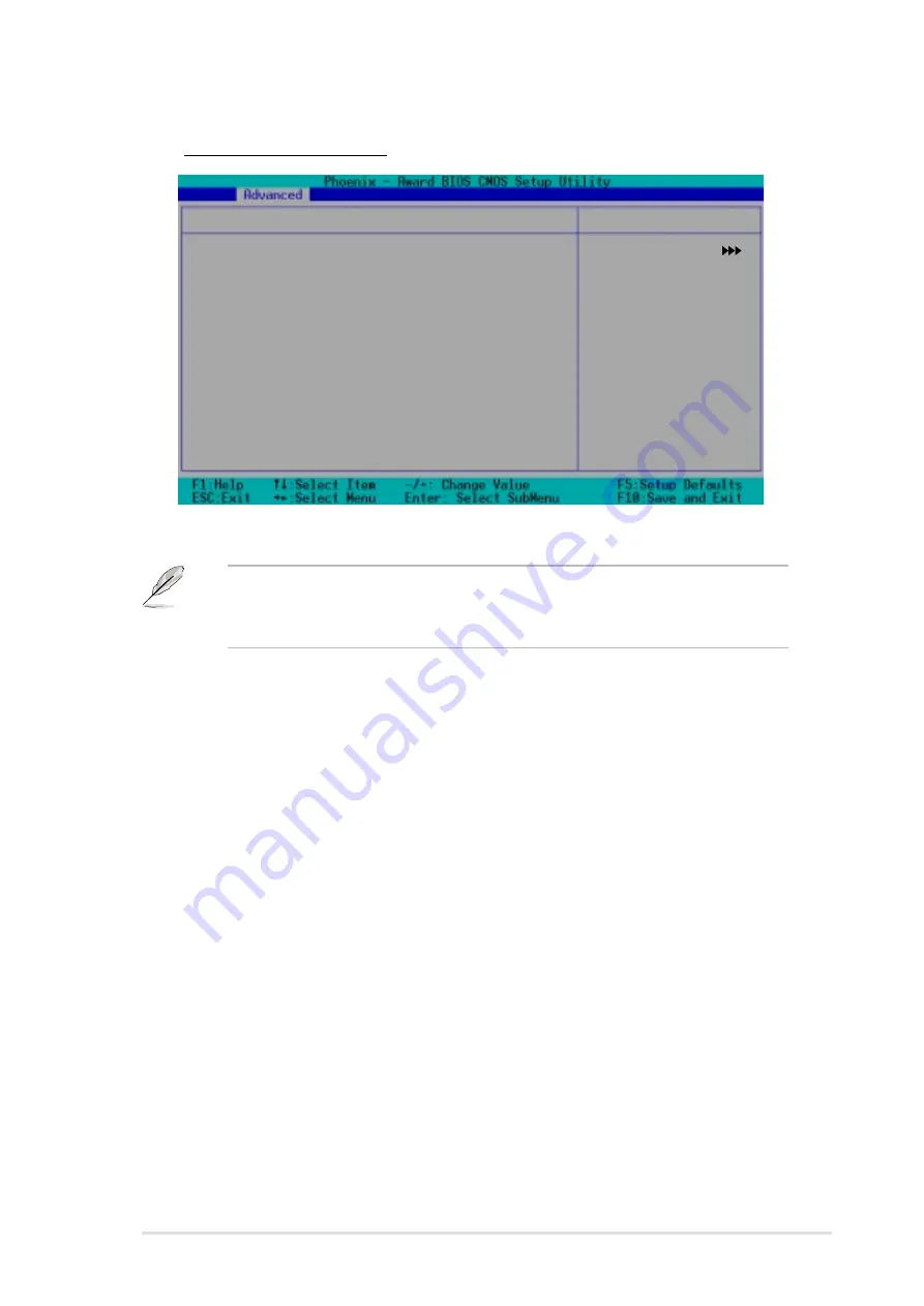
*** On-Chip Serial ATA Setting ***
On-Chip Serial ATA
[Auto]
SATA Mode
IDE
Serial ATA Port0 Mode
SATA0 master
Serial ATA Port1 Mode
SATA1 master
SATA Configuration
Select Menu
Item Specific Help
[Disabled]: Disable
SATA Controller.
[Auto]: Auto-arrange
the BIOS.
[Combined Mode]: PATA
and SATA are combined.
Max. of 2 IDE drives on
each channel.
[Enhanced Mode]: Enable
both SATA and PATA.
Max. of 6 IDE drives
are supported.
[SATA Only]: SATA is
opeating in legacy
mode.
S A T A C o n f i g u r a t i o n
S A T A C o n f i g u r a t i o n
S A T A C o n f i g u r a t i o n
S A T A C o n f i g u r a t i o n
S A T A C o n f i g u r a t i o n
***On-Chip Serial ATA Setting***
***On-Chip Serial ATA Setting***
***On-Chip Serial ATA Setting***
***On-Chip Serial ATA Setting***
***On-Chip Serial ATA Setting***
The SATA Mode and Serial ATA Port0 Mode items are configurable
only when the On-Chip Serial ATA item is set to [ Combined Mode]
[Enhanced Mode] or [SATA Only].
On-chip Serial ATA [Auto]
On-chip Serial ATA [Auto]
On-chip Serial ATA [Auto]
On-chip Serial ATA [Auto]
On-chip Serial ATA [Auto]
This item allows you to configure your serial ATA devices, if present.
Configuration options: [Disabled] [Auto] [Combined Mode]
[Enhanced Mode] [SATA Only]
a.
Setting to [A u t o
A u t o
A u t o
A u t o
A u t o] allows BIOS to automatically configure the SATA
devices.
b.
Setting to [C o m b i n e d M o d e
C o m b i n e d M o d e
C o m b i n e d M o d e
C o m b i n e d M o d e
C o m b i n e d M o d e] allows you to install parallel ATA and
serial ATA devices at the same time. You may install t w o I D E
t w o I D E
t w o I D E
t w o I D E
t w o I D E
d e v i c e s o n a n y o f t h e p a r a l l e l A T A c h a n n e l s
d e v i c e s o n a n y o f t h e p a r a l l e l A T A c h a n n e l s
d e v i c e s o n a n y o f t h e p a r a l l e l A T A c h a n n e l s
d e v i c e s o n a n y o f t h e p a r a l l e l A T A c h a n n e l s
d e v i c e s o n a n y o f t h e p a r a l l e l A T A c h a n n e l s, and o n e I D E
o n e I D E
o n e I D E
o n e I D E
o n e I D E
d e v i c e o n e a c h s e r i a l A T A c h a n n e l
d e v i c e o n e a c h s e r i a l A T A c h a n n e l
d e v i c e o n e a c h s e r i a l A T A c h a n n e l
d e v i c e o n e a c h s e r i a l A T A c h a n n e l
d e v i c e o n e a c h s e r i a l A T A c h a n n e l for a maximum of f o u r
f o u r
f o u r
f o u r
f o u r
devices. Use ths option when you installed a legacy operating system
like MS-DOS, Windows ME/98/NT4.0.
c.
Setting to [E n h a n c e d M o d e
E n h a n c e d M o d e
E n h a n c e d M o d e
E n h a n c e d M o d e
E n h a n c e d M o d e] allows you to install parallel ATA and
serial ATA devices at the same time, with a maximum of s i x
s i x
s i x
s i x
s i x IDE
devices on each channel. Use this option when you installed a native
operating system like Windows 2000/XP.
d.
Setting to [S A T A O n l y
S A T A O n l y
S A T A O n l y
S A T A O n l y
S A T A O n l y] allows you to install IDE devices on the
Serial ATA channels only.
e.
Setting to [D i s a b l e d
D i s a b l e d
D i s a b l e d
D i s a b l e d
D i s a b l e d] disables the onboard SATA controller. The
RAID feature is also disabled.
Summary of Contents for NCCH-DR
Page 1: ...Motherboard NCCH DR Series ...
Page 12: ...x i i x i i x i i x i i x i i ...


