


1-22
Chapter 1: Product introduction
10. USB 2.0 ports 3 and 4. These two 4-pin Universal Serial Bus (USB)
ports are available for connecting USB 2.0 devices.
11. USB 2.0 ports 1 and 2. These two 4-pin Universal Serial Bus (USB)
ports are available for connecting USB 2.0 devices.
12. Serial port (COM port). This 9-pin COM port is for pointing devices and
other serial devices.
13. Coaxial S/PDIF Out port. This port connects an external audio output
device via a coaxial S/PDIF cable.
14. PS/2 keyboard port. This purple connector is for a PS/2 keyboard.
7. Line Out port (lime). This port connects a headphone or a speaker. In
4-channel, 6-channel, and 8-channel configuration, the function of this
port becomes Front Speaker Out.
8. Microphone port (pink). This port connects a microphone.
9. Center/Subwoofer port (orange). This port connects the center/
subwoofer speakers.
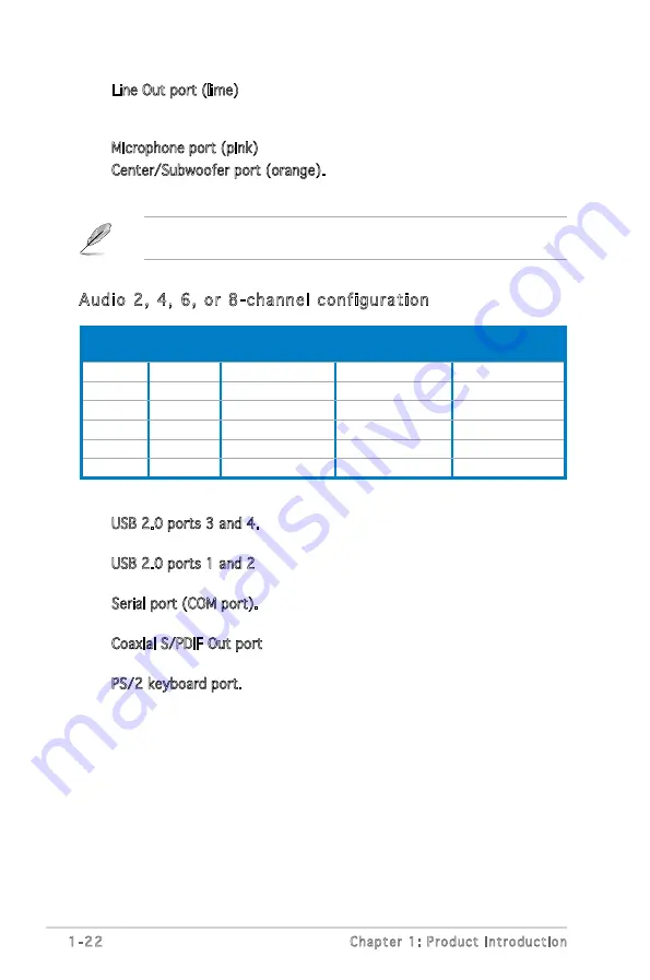
Refer to the audio configuration table below for the function of the audio
ports in 2, 4, 6, or 8-channel configuration.
Port
Headset
2-channel
4-channel
6-channel
8-channel
Light Blue
Line In
Line In
Line In
Line In
Lime
Line Out
Front Speaker Out Front Speaker Out Front Speaker Out
Pink
Mic In
Mic In
Mic In
Mic In
Gray
–
–
–
Side Speaker Out
Black
–
Rear Speaker Out
Rear Speaker Out
Rear Speaker Out
Orange
–
–
Center/Subwoofer
Center/Subwoofer
Audio 2, 4, 6, or 8-channel configuration
Summary of Contents for Motherboard M2S-X
Page 1: ...Motherboard M2S X ...
Page 12: ...xii ...
Page 42: ...1 30 Chapter 1 Product introduction ...
Page 80: ...2 38 Chapter 2 BIOS Setup ...


