background image

ASUS M4A88TD-V EVO

2-31

Chapter 2

4. 

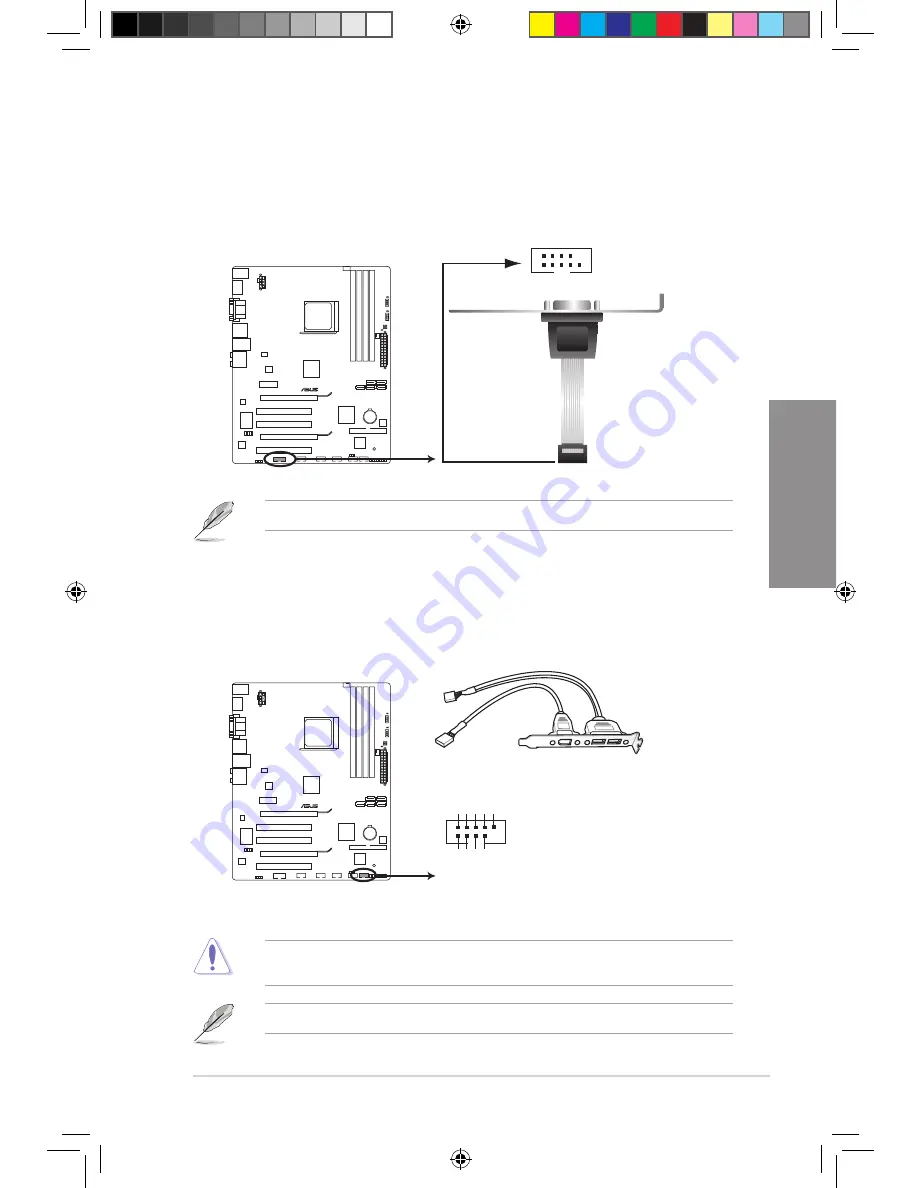
IEEE 1394a port connector (10-1 pin IE1394_1)

This connector is for an IEEE 1394a port. Connect the IEEE 1394a module cable to this 

connector, then install the module to a slot opening at the back of the system chassis. 

Never connect a USB cable to the IEEE 1394a connector. Doing so will damage the 

motherboard!

The IEEE 1394a module is purchased separately.

3. 

Serial port connector (10-1 pin COM1)

This connector is for a serial (COM) port. Connect the serial port module cable to this 

connector, then install the module to a slot opening at the back of the system chassis.

The COM module is purchased separately.

M4A88TD-V EVO

M4A88TD-V EVO  

IEEE 1394a Connector

PIN 1

TPA1-

GND

TPB1-

+12V

GND

TPA1+

GND

TPB1+

+12V

IE1394_1

M4A88TD-V EVO

M4A88TD-V EVO Serial port (COM1) connector

PIN 1

COM1

E5889_M4A88TD-V EVO_Contents V2.31   31

5/26/10   4:04:28 PM

Summary of Contents for M4A88TD-V EVO

Page 1: ...Motherboard M4A88TD V EVO E5889_M4A88TD V EVO_Contents V2 1 1 5 26 10 4 03 13 PM ...

Page 2: ...enefit without intent to infringe Offer to Provide Source Code of Certain Software This product may contain copyrighted software that is licensed under the General Public License GPL and under the Lesser General Public License Version LGPL The GPL and LGPL licensed code in this product is distributed without any warranty Copies of these licenses are included in this product You may obtain the comp...

Page 3: ... 2 2 2 1 Motherboard layout 2 2 2 2 2 Layout contents 2 3 2 2 3 Placement direction 2 4 2 2 4 Screw holes 2 4 2 3 Central Processing Unit CPU 2 5 2 3 1 Installing the CPU 2 5 2 3 2 Installing the CPU heatsink and fan 2 7 2 4 System memory 2 10 2 4 1 Overview 2 10 2 4 2 Memory configurations 2 11 2 4 3 Installing a DIMM 2 16 2 4 4 Removing a DIMM 2 16 2 5 Expansion slots 2 17 2 5 1 Installing an ex...

Page 4: ... setup program 3 9 3 3 1 BIOS menu screen 3 9 3 3 2 Menu bar 3 9 3 3 3 Navigation keys 3 10 3 3 4 Menu items 3 10 3 3 5 Submenu items 3 10 3 3 6 Configuration fields 3 10 3 3 7 Pop up window 3 10 3 3 8 Scroll bar 3 10 3 3 9 General help 3 10 3 4 Main menu 3 11 3 4 1 SATA 1 2 3 5 6 E SATA 3 11 3 4 2 SATA Configuration 3 13 3 4 3 System Information 3 14 3 5 Ai Tweaker menu 3 15 3 5 1 CPU Level UP 3 ...

Page 5: ...tion 3 23 3 6 2 Chipset 3 25 3 6 3 Onboard Devices Configuration 3 28 3 6 4 PCIPnP 3 29 3 6 5 USB Configuration 3 30 3 7 Power menu 3 31 3 7 1 Suspend Mode 3 31 3 7 2 ACPI 2 0 Support 3 31 3 7 3 ACPI APIC Support 3 31 3 7 4 APM Configuration 3 32 3 7 5 Hardware Monitor 3 33 3 7 6 Anti Surge Support 3 34 3 7 7 NB Thermal Protect 3 34 3 8 Boot menu 3 35 3 8 1 Boot Device Priority 3 35 3 8 2 Boot Set...

Page 6: ...disks 4 14 4 5 3 Setting the RAID item in BIOS 4 14 4 5 4 AMD Option ROM Utility 4 15 4 6 Creating a RAID driver disk 4 18 4 6 1 Creating a RAID driver disk without entering the OS 4 18 4 6 2 Creating a RAID driver disk in Windows 4 18 4 6 3 Installing the RAID driver during Windows OS installation 4 18 4 6 4 Using a USB floppy disk drive 4 19 Chapter 5 ATI CrossFireX technology support 5 1 ATI Cr...

Page 7: ...ceiver is connected Consult the dealer or an experienced radio TV technician for help Canadian Department of Communications Statement This digital apparatus does not exceed the Class B limits for radio noise emissions from digital apparatus set out in the Radio Interference Regulations of the Canadian Department of Communications This class B digital apparatus complies with Canadian ICES 003 The u...

Page 8: ...re about the voltage of the electrical outlet you are using contact your local power company If the power supply is broken do not try to fix it by yourself Contact a qualified service technician or your retailer Operation safety Before installing the motherboard and adding devices on it carefully read all the manuals that came with the package Before using the product ensure all cables are correct...

Page 9: ...ons of the BIOS parameters are also provided Chapter 4 Software support This chapter describes the contents of the support DVD that comes with the motherboard package and the software Chapter 5 ATI CrossFireX technology support This chapter describes the ATI CrossFireX feature and shows the graphics card installation procedures Where to find more information Refer to the following sources for addi...

Page 10: ...Example Enter means that you must press the Enter or Return key Key1 Key2 Key3 If you must press two or more keys simultaneously the key names are linked with a plus sign Example Ctrl Alt Del DANGER WARNING Information to prevent injury to yourself when trying to complete a task CAUTION Information to prevent damage to the components when trying to complete a task IMPORTANT Instructions that you M...

Page 11: ...output Integrated ATI Radeon HD 4250 GPU Dual independent displays support D Sub DVI D D Sub HDMI Supports HDMI with max resolution 1920 x 1200 1080P Supports DVI D with max resolution 2560 x 1600 60Hz Supports RGB with max resolution 2048 x 1536 85Hz Supports H 264 VC 1 MPEG 2 DirectX 10 1 and OpenGL 2 0 Supports Shader Model 4 1 Universal Video Decoder UVD 2 0 Maximum UMA memory size 1 GB 128 MB...

Page 12: ... Fanless Design Stylish heatsink solution ASUS Fan Xpert ASUS EZ DIY ASUS O C Profile ASUS CrashFree BIOS 3 ASUS EZ Flash 2 ASUS MyLogo 2 ASUS exclusive overclocking features Intelligent overclocking tools TurboV EVO GPU Boost Turbo Key II Precision Tweaker 2 vCore Adjustable CPU voltage at 0 003125V increment vDIMM Adjustable DRAM voltage at 0 015V increment vChipset N B Adjustable chipset voltag...

Page 13: ...x S PDIF Out header 1 x Core Unlocker switch 1 x Turbo Key II switch 1 x MemOK button 1 x Front panel audio connector 1 x COM connector 24 pin ATX Power connector 8 pin EATX 12V Power connector 1 x System panel connector BIOS features 16 Mb Flash ROM SPI AMI BIOS PnP DMI 2 0 WfM 2 0 SM BIOS 2 5 ACPI 2 0a ASUS EZ Flash 2 ASUS CrashFree BIOS 3 Manageability WOL by PME WOR by PME WOR by Ring PXE Supp...

Page 14: ...xiv E5889_M4A88TD V EVO_Contents V2 14 14 5 26 10 4 03 23 PM ...

Page 15: ...n your package with the list below 1 2 Package contents Check your motherboard package for the following items If any of the above items is damaged or missing contact your retailer The illustrated items above are for reference only Actual product specifications may vary with different models UserManual ASUS M4A88TD V EVO motherboard User guide Support DVD 2 x Serial ATA 6 0 Gb s cables with 6 0 Gb...

Page 16: ... performance ATI CrossFireX Technology ATI s CrossFireX boosts image quality along with rendering speed eliminating the need to scale down screen resolution to get high quality images CrossFireX allows higher antialiasing anisotropic filtering shading and texture settings Adjust your display configurations experiment with the advanced 3D settings and check the effects with a real time 3D rendered ...

Page 17: ...features ASUS Power Solutions ASUS Power solutions intelligently and automatically provide balanced computing power and energy consumption 8 2 Phase Power Design To fully unleash the next generation AM3 CPU s potential this motherboard has adopted the brand new 8 phase VRM power design which delivers high power efficiency and supreme overclocking ability These high quality power components effecti...

Page 18: ...ons in different geographic regions and your PC s loading The built in variety of useful profiles offer flexible controls of fan speed to achieve a quiet and cool environment ASUS EZ DIY ASUS EZ DIY feature collection provides you with easy ways to install computer components update the BIOS or back up your favorite settings ASUS O C Profile The motherboard features the ASUS O C Profile that allow...

Page 19: ...r supply case to avoid damaging them due to static electricity Hold components by the edges to avoid touching the ICs on them Whenever you uninstall any component place it on a grounded antistatic pad or in the bag that came with the component Before you install or remove any component ensure that the ATX power supply is switched off or the power cord is detached from the power supply Failure to d...

Page 20: ...er I O ALC 892 RTL 8111E ICS 477C KB_USB56 SPDIFO_ HDMI 16Mb BIOS SB_PWR VT6330 CLRTC 24 4cm 9 6in AMD 880G AMD SB850 DDR3 DIMM_B1 64bit 240 pin module SOCKET AM3 DDR3 DIMM_B2 64bit 240 pin module DDR3 DIMM_A1 64bit 240 pin module DDR3 DIMM_A2 64bit 240 pin module SATA6 SATA3 SATA1 SATA5 SATA2 AUDIO LAN1_USB12 F_ ESATA_ USB34 PWR_FAN CHA_FAN PANEL SPDIF_OUT COM1 30 5cm 12 0in MemOK DRAM_LED O2LED1...

Page 21: ...MemOK switch 2 22 10 DRAM LED DRAM_LED 2 38 11 AMD SB850 Serial ATA 6 0 Gb s connectors 7 pin SATA1 SATA2 SATA3 SATA5 SATA6 2 30 12 IDE connector 40 1 pin PRI_EIDE 2 29 13 Clear RTC RAM 3 pin CLRTC 2 20 14 Standby power LED SB_PWR 2 38 15 System panel connector 20 8 pin PANEL 2 36 16 IEEE 1394a port connector 10 1 pin IE1394_1 2 31 17 USB connectors 10 1 pin USB78 USB910 USB1112 USB1314 2 32 18 Se...

Page 22: ...ion The edge with external ports goes to the rear part of the chassis as indicated in the image below 2 2 4 Screw holes Place nine screws into the holes indicated by circles to secure the motherboard to the chassis DO NOT overtighten the screws Doing so can damage the motherboard Place this side towards the rear of the chassis E5889_M4A88TD V EVO_Contents V2 4 4 5 26 10 4 03 35 PM ...

Page 23: ...orientation DO NOT force the CPU into the socket to prevent bending the connectors on the socket and damaging the CPU Ensure that all power cables are unplugged before installing the CPU 2 3 1 Installing the CPU To install a CPU 1 Locate the CPU socket on the motherboard Ensure that the socket lever is lifted up to a 90º angle Otherwise the CPU will not fit in completely 2 Press the lever sideways...

Page 24: ...locked Gold triangle Small triangle 6 Apply some Thermal Interface Material to the exposed area of the CPU that the heatsink will be in contact with ensuring that it is spread in an even thin layer Some heatsinks come with pre applied thermal paste If so skip this step The Thermal Interface Material is toxic and inedible DO NOT eat it If it gets into your eyes or touches your skin wash it off imme...

Page 25: ...ism If the instructions in this section do not match the CPU documentation follow the latter The retention module base is already installed on the motherboard upon purchase You do not have to remove the retention module base when installing the CPU or installing other motherboard components If you purchased a separate CPU heatsink and fan assembly ensure that a Thermal Interface Material is proper...

Page 26: ...base A clicking sound denotes that the retention bracket is in place 4 Push down the retention bracket lock on the retention mechanism to secure the heatsink and fan to the module base Ensure that the fan and heatsink assembly perfectly fits the retention mechanism module base otherwise you cannot snap the retention bracket in place E5889_M4A88TD V EVO_Contents V2 8 8 5 26 10 4 03 48 PM ...

Page 27: ... labeled CPU_FAN Do not forget to connect the CPU fan connector Hardware monitoring errors can occur if you fail to plug this connector This connector is backward compatible with old 3 pin CPU fan CPU_FAN CPU FAN PWM CPU FAN IN CPU FAN PWR GND M4A88TD V EVO M4A88TD V EVO CPU fan connector E5889_M4A88TD V EVO_Contents V2 9 9 5 26 10 4 03 49 PM ...

Page 28: ...revent installation on a DDR2 DIMM socket DDR3 modules are developed for better performance with less power consumption The figure illustrates the location of the DDR3 DIMM sockets Recommended memory configurations One DIMM Install one memory module in any slot as a single channel operation Two DIMMs dual channel operation Four DIMMs dual channel operation M4A88TD V EVO M4A88TD V EVO 240 pin DDR3 ...

Page 29: ...ped for single channel operation We recommend that you install the memory modules from the blue slots for better overclocking capability Always install DIMMs with the same CAS latency For optimum compatibility we recommend that you obtain memory modules from the same vendor AMD AM3 100 and 200 Series CPU support up to DDR3 1066 MHz When overclocking some AMD CPUs may not support DDR3 1600 or highe...

Page 30: ...art No Size SS DS Chip Brand Chip No Timing Voltage DIMM support 1 DIMM 2 DIMM 4 DIMM A Data AD31600E001GM O U3K 3072MB Kit of 3 SS 8 8 8 24 1 65V 1 85V A Data AD31600X002GMU XMP 4096MB Kit of 2 DS 7 7 7 20 1 75 1 85V CORSAIR TR3X3G1600C8D XMP 3072MB Kit of 3 SS 8 8 8 24 1 65V CORSAIR CMX4GX3M2A1600C9 XMP 4096MB Kit of 2 DS 9 9 9 24 1 65V CORSAIR CMX4GX3M2A1600C9 XMP 4096MB Kit of 2 DS 9 9 9 24 1 ...

Page 31: ...3 1333MHz capability Vendor Part No Size SS DS Chip Brand Chip No Timing Voltage DIMM support 1 DIMM 2 DIMM 4 DIMM A Data AD31333001GOU 1024MB SS A Data AD30908C8D 151C E0906 A Data AD31333G001GOU 3072MB Kit of 3 SS 8 8 8 24 1 65 1 85V A Data AD31333002GOU 2048MB DS A Data AD30908C8D 151C E0903 A Data AD31333G002GMU 2048MB DS 8 8 8 24 1 65 1 85V Apacer 78 A1GC6 9L1 2048MB DS APACER AM5D5808DEWSBG ...

Page 32: ...XMP 3072MB Kit of 3 SS 1 6V OCZ OCZ3P1333LV4GK 4096MB Kit of 2 DS 7 7 7 20 1 65V OCZ OCZ3P1333LV4GK 4096MB Kit of 2 DS 7 7 7 20 1 65V OCZ OCZ3RPX1333EB4GK 4096MB Kit of 2 DS 6 5 5 20 1 85V OCZ OCZ3X13334GK XMP 4096MB Kit of 2 DS 7 7 7 20 1 75V OCZ OCZ3G1333LV6GK 6144MB Kit of 3 DS 9 9 9 20 1 65V OCZ OCZ3P1333LV6GK 6144MB Kit of 3 DS 7 7 7 20 1 65V OCZ OCZ3X1333LV6GK XMP 6144MB Kit of 3 DS 8 8 8 20...

Page 33: ...12872AZ 1G1F1 1024MB SS Micron 9HF22D9KPT ECC 7 Micron MT16JTF25664AZ 1G1F1 2048MB DS Micron 9HF22D9KPT 7 Micron MT18JSF25672AZ 1G1F1 2048MB DS Micron 9GF22D9KPT ECC 7 SAMSUNG M378B2873EH1 CF8 1024MB SS Samsung SEC 901 HCF8 K4B1G0846E Elixir M2Y2G64CB8HC5N BE 2048MB DS Elixir N2CB1G80CN BE Elixir M2Y2G64CBHA9N BE 2048MB DS 7 7 7 20 Elixir M2Y2G64CBHC9N BE 2048MB DS Elixir Kingtiger 2GB DIMM PC3 85...

Page 34: ...y further to ensure proper sitting of the DIMM 1 Unlock a DIMM socket by pressing the retaining clips outward 2 Align a DIMM on the socket such that the notch on the DIMM matches the DIMM slot key on the socket A DIMM is keyed with a notch so that it fits in only one direction DO NOT force a DIMM into a socket in the wrong direction to avoid damaging the DIMM Locked Retaining Clip 3 2 1 Always ins...

Page 35: ...s with the screw you removed earlier 6 Replace the system cover 2 5 2 Configuring an expansion card After installing the expansion card configure it by adjusting the software settings 1 Turn on the system and change the necessary BIOS settings if any See Chapter 3 for information on BIOS setup 2 Assign an IRQ to the card Refer to the tables on the next page 3 Install the software drivers for the e...

Page 36: ...System CMOS Real Time Clock 9 4 IRQ Holder for PCI Steering 10 5 IRQ Holder for PCI Steering 11 6 IRQ Holder for PCI Steering 12 7 Reserved 13 8 Numeric Data Processor 14 9 Primary IDE Channel IRQ assignments for this motherboard A B C D E F G H PCIE x16_1 shared PCIE x16_2 shared PCIE x1_1 shared PCI_1 shared PCI_2 shared PCI_3 shared LAN shared Onboard 880G Video Controller shared Onchip SATA Co...

Page 37: ...er cards that comply with the PCI Express specifications Refer to the figure below for the location of the slots 2 5 6 PCI Express 2 0 x16 slots This motherboard has two PCI Express 2 0 x16 slots that support PCI Express 2 0 x16 graphics cards complying with the PCI Express specifications Refer to the figure below for the location of the slots PCIe 2 0 x16_1 slot blue at x 16 link PCIe 2 0 x16_2 s...

Page 38: ...me Clock RTC RAM in CMOS You can clear the CMOS memory of date time and system setup parameters by erasing the CMOS RTC RAM data The onboard button cell battery powers the RAM data in CMOS which include system setup information such as system passwords To erase the RTC RAM 1 Turn OFF the computer and unplug the power cord 2 Move the jumper cap from pins 1 2 default to pins 2 3 Keep the cap on pins...

Page 39: ... O2LED2 LED If you clear the CMOS or load the BIOS setup defaults the related overclocking items in the BIOS menu follow the current setting of the Turbo Key II switch If you change the switch setting to Enable under the OS environment the Turbo Key II function will be activated after the next system bootup You may use the TurboV Auto Tuning overclock in the BIOS setup program and enable the Turbo...

Page 40: ...DRAM_LED increases indicating different test processes Due to memory tuning requirement the system automatically reboots when each timing set is tested If the installed DIMMs still fail to boot after the whole tuning process the DRAM_LED lights continuously Replace the DIMMs with ones recommended in the Memory QVL Qualified Vendors Lists in this user manual or on the ASUS website at www asus com I...

Page 41: ...ear the CMOS or load the BIOS setup defaults the ASUS Core Unlocker item in the BIOS menu follows the current setting of the Core Unlocker switch You may also press 4 during the Power On Self Test POST to activate the Core Unlocker function The system will use the last setting you have made For ensuring the system performance turn the switch setting to Enable when the system is powered off M4A88TD...

Page 42: ... LAN RJ 45 port 11 USB 2 0 ports 1 and 2 6 USB 2 0 ports 5 and 6 12 Audio I O ports and Refer to the tables on the next page for LAN port and audio port definitions Refer to the notes and troubleshooting on HDTV overscaling or underscaling on the next pages DO NOT insert a different connector to the external SATA port To use hot plugging set the SATA Port1 Port4 item in the BIOS to AHCI Refer to 3...

Page 43: ...E Linked ORANGE 100 Mbps connection BLINKING Data activity GREEN 1 Gbps connection Dual display table This table indicates whether the dual display you want to use is supported or not Dual display output Supported Not supported DVI D Sub HDMI D Sub DVI HDMI Playback of Blu Ray Discs For better playback quality we suggest that you follow the system requirements in the suggested list below Suggested...

Page 44: ...I 1 4 Click Scaling Options 5 Move the Underscan Overscan slider to adjust the overall size of the display on the HDMI DTV Using this slider increases or decreases any black borders that may be visible around the outside of the display The Scaling Options function of the DTV HDMI 1 item in the ATI CATALYST Control Center is adjustable only when you are using an HDTV compliance resolution such as 4...

Page 45: ...ASUS M4A88TD V EVO 2 27 Chapter 2 2 8 2 Audio I O connections Audio I O ports Connect to Headphone and Mic Connect to Stereo 2 1 channel Speakers E5889_M4A88TD V EVO_Contents V2 27 27 5 26 10 4 04 21 PM ...

Page 46: ...2 28 Chapter 2 Hardware information Chapter 2 Connect to 4 1 channel Speakers Connect to 7 1 channel Speakers Connect to 5 1 channel Speakers E5889_M4A88TD V EVO_Contents V2 28 28 5 26 10 4 04 23 PM ...

Page 47: ...ble for Ultra DMA 133 100 66 IDE devices If any device jumper is set as Cable Select ensure that all other device jumpers have the same setting 1 IDE connector 40 1 pin PRI_EIDE The onboard IDE connector is for the Ultra DMA 133 100 66 signal cable There are three connectors on each Ultra DMA 133 100 66 signal cable blue black and gray Connect the blue connector to the motherboard s IDE connector ...

Page 48: ...connectors to RAID in the BIOS See section 3 4 2 SATA Configuration for details You must install Windows XP Service Pack 2 or later version before using Serial ATA hard disk drives The Serial ATA RAID feature is available only if you are using Windows XP SP2 or later version When using hot plug and NCQ set the type of the SATA connectors to AHCI in the BIOS See section 3 4 2 SATA Configuration for...

Page 49: ...motherboard The IEEE 1394a module is purchased separately 3 Serial port connector 10 1 pin COM1 This connector is for a serial COM port Connect the serial port module cable to this connector then install the module to a slot opening at the back of the system chassis The COM module is purchased separately M4A88TD V EVO M4A88TD V EVO IEEE 1394a Connector PIN 1 TPA1 GND TPB1 12V GND TPA1 GND TPB1 12V...

Page 50: ...amage the motherboard You can connect the front panel USB cable to the ASUS Q Connector USB blue first and then install the Q Connector USB to the USB connector onboard if your chassis supports front panel USB ports The USB module cable is purchased separately M4A88TD V EVO M4A88TD V EVO USB2 0 connectors USB 5V USB_P8 USB_P8 GND NC USB 5V USB_P7 USB_P7 GND USB78 PIN 1 USB 5V USB_P10 USB_P10 GND N...

Page 51: ...omponents These are not jumpers Do not place jumper caps on the fan connectors The CPU_FAN connector supports the CPU fan of maximum 2A 24 W fan power Only the 4 pin CPU_FAN and 3 pin CHA_FAN connectors support the ASUS Fan Xpert feature If you install two VGA cards we recommend that you plug the rear chassis fan cable to the motherboard connector labeled CHA_FAN for better thermal environment CHA...

Page 52: ...panel audio module to this connector to avail of the motherboard s high definition audio capability If you want to connect a high definition front panel audio module to this connector set the Front Panel Select item in the BIOS setup to HD Audio if you want to connect an AC 97 front panel audio module to this connector set the item to AC 97 By default this connector is set to HD Refer to 3 6 3 Onb...

Page 53: ...tput when configuring a system with more power consuming devices The system may become unstable or may not boot up if the power is inadequate If you are uncertain about the minimum power supply requirement for your system refer to the Recommended Power Supply Wattage Calculator at http support asus com PowerSupplyCalculator PSCalculator aspx SLanguage en us for details If you want to use two high ...

Page 54: ...r 4 pin SPEAKER This 4 pin connector is for the chassis mounted system warning speaker The speaker allows you to hear system beeps and warnings ATX power button soft off button 2 pin PWRSW This connector is for the system power button Reset button 2 pin RESET This 2 pin connector is for the chassis mounted reset button for system reboot without turning off the system power 10 System panel connecto...

Page 55: ...ons and then match them to their respective front panel cable labels The labels on the front panel cables may vary depending on the chassis model 2 Install the ASUS Q Connector to the system panel connector ensuring the orientation matches the labels on the motherboard 3 The front panel functions are now enabled The figure shows the Q Connector is properly installed on the motherboard IDE_LED POWE...

Page 56: ...erboard component The illustration below shows the location of the onboard LED 2 DRAM LED DRAM LED checks the DRAM in sequence during motherboard booting process If an error is found the LED next to the error device will continue lighting until the problem is solved This user friendly design provides an intuitional way to locate the root problem within a second M4A88TD V EVO SB_PWR ON Standby Powe...

Page 57: ... Core Unlocker LED lights when the Core Unclocker switch is turned to Enable The Core Unlocker LED keeps on lighting even though the ASUS Core Unlocker item in the BIOS menu is set to Disabled M4A88TD V EVO M4A88TD V EVO Turbo Key II LED O2LED2 M4A88TD V EVO M4A88TD V EVO Core Unlocker LED O2LED1 E5889_M4A88TD V EVO_Contents V2 39 39 5 26 10 4 04 40 PM ...

Page 58: ...eps see the BIOS beep codes table below or additional messages appear on the screen If you do not see anything within 30 seconds from the time you turned on the power the system may have failed a power on test Check the jumper settings and connections or call your retailer for assistance 7 At power on hold down the Delete key to enter the BIOS Setup Follow the instructions in Chapter 3 BIOS Beep D...

Page 59: ... the system s failure to boot Carefully follow the instructions of this chapter to update your BIOS if necessary Visit the ASUS website www asus com to download the latest BIOS file for this motherboard The following utilities allow you to manage and update the motherboard BIOS setup program 1 ASUS Update Updates the BIOS in Windows environment 2 ASUS EZ Flash 2 Updates the BIOS using a USB flash ...

Page 60: ... an Internet connection either through a network or an Internet Service Provider ISP Installing ASUS Update To install ASUS Update 1 Place the support DVD in the optical drive 2 From the Main menu click the Utilities tab then click Install ASUS Update VX XX XX 3 The ASUS Update utility is copied to your system Quit all Windows applications before you update the BIOS using this utility Updating the...

Page 61: ... a file from the dropdown menu then click Next M4A88TDV M4A88TDV ROM Ensure to load the BIOS default settings to ensure system compatibility and stability Select the Load Setup Defaults item under the Exit menu See section 3 10 Exit Menu for details 5 Follow the onscreen instructions to complete the update process The ASUS Update utility is capable of updating itself through the Internet Always up...

Page 62: ...p program Go to the Tools menu to select EZ Flash 2 and press Enter to enable it 2 Press Tab to switch between drives until the correct BIOS file is found When the correct BIOS file is found EZ Flash 2 performs the BIOS update process and automatically reboots the system when done This function can support devices such as a USB flash disk with FAT 32 16 format and single partition only DO NOT shut...

Page 63: ...le at support asus com and save it to a USB flash drive Recovering the BIOS To recover the BIOS 1 Turn on the system 2 Insert the motherboard support DVD to the optical drive or the USB flash drive containing the BIOS file to the USB port 3 The utility automatically checks the devices for the BIOS file When found the utility reads the BIOS file and starts flashing the corrupted BIOS file 4 Turn of...

Page 64: ...e BIOS in DOS environment This utility also allows you to copy the current BIOS file that you can use as a backup when the BIOS fails or gets corrupted during the updating process The succeeding utility screens are for reference only The actual utility screen displays may not be same as shown Before updating BIOS 1 Prepare the motherboard support DVD and a USB flash drive in FAT32 16 format and si...

Page 65: ...OS To back up the current BIOS file using the BIOS Updater Ensure that the USB flash drive is not write protected and has enough free space to save the file 1 At the FreeDOS prompt type bupdater o filename and press Enter The filename is any user assigned filename with no more than eight alphanumeric characters for the filename and three alphanumeric characters for the extension Update ROM E5889_M...

Page 66: ...to connect all SATA hard disk drives after updating the BIOS file if you have disconnected them Updating the BIOS file To update the BIOS file using BIOS Updater 1 At the FreeDOS prompt type bupdater pc g and press Enter D bupdater pc g 2 The BIOS Updater screen appears as below 3 Press Tab to switch between screen fields and use the Up Down Home End keys to select the BIOS file and press Enter BI...

Page 67: ... and may not exactly match what you see on your screen If the system becomes unstable after changing any BIOS setting load the default settings to ensure system compatibility and stability Select the Load Setup Defaults item under the Exit menu See section 3 10 Exit Menu for details If the system fails to boot after changing any BIOS setting try to clear the CMOS and reset the motherboard to the d...

Page 68: ... fields These fields show the values for the menu items If an item is user configurable you can change the value of the field opposite the item You cannot select an item that is not user configurable A configurable field is enclosed in brackets and is highlighted when selected To change the value of a field select it and press Enter to display a list of options Refer to 3 3 7 Pop up window 3 3 7 P...

Page 69: ...SATA 1 2 3 5 6 E SATA While entering Setup the BIOS automatically detects the presence of SATA devices There is a separate submenu for each SATA device Select a device item and press Enter to display the SATA device information The BIOS automatically detects the values opposite the dimmed items Device Vendor Size LBA Mode Block Mode PIO Mode Async DMA Ultra DMA and SMART Monitoring These values ar...

Page 70: ...nd to the device occurs one sector at a time PIO Mode Auto Auto Allows automatic selection of the PIO Programmed input output modes which correspond to different data transfer rates 0 1 2 3 4 Sets the PIO mode to Mode 0 1 2 3 or 4 DMA Mode Auto DMA Direct Memory Access allows your computer to transfer data to and from the hardware devices installed with much less CPU overhead The DMA mode consists...

Page 71: ...hen you want to create a RAID configuration from the SATA hard disk drives AHCI Set to AHCI when you want the SATA hard disk drives to use the AHCI Advanced Host Controller Interface The AHCI allows the onboard storage driver to enable advanced Serial ATA features that increases storage performance on random workloads by allowing the drive to internally optimize the order of commands When this ite...

Page 72: ...ystem Information This menu gives you an overview of the general system specifications The BIOS automatically detects the BIOS information CPU specification and system memory in this menu E5889_M4A88TD V EVO_Contents V2 14 14 5 26 10 4 05 06 PM ...

Page 73: ...tious when changing the settings of the Ai Tweaker menu items Incorrect field values can cause the system to malfunction The configuration options for this chapter vary depending on the CPU and DIMM model you installed on the motherboard Scroll down to display the following items E5889_M4A88TD V EVO_Contents V2 15 15 5 26 10 4 05 08 PM ...

Page 74: ...he numeric keypad The values range from 100 to 150 3 5 2 CPU OverClocking Auto Allows you to select the CPU overclocking options to achieve the desired CPU internal frequency Select any of these preset overclocking configuration options Manual Allows you to individually set overclocking parameters Auto Loads the optimal settings for the system D O C P Allows you to select a DRAM O C profile and th...

Page 75: ...s Auto Overclock 2 Overclock 5 Overclock 8 Overclock 10 3 5 3 CPU Ratio Auto Allows you to set the ratio between the CPU Core Clock and the FSB Frequency Use the and keys to adjust the ratio The valid value ranges vary according to your CPU model The following two items appear only when you installed a 6 core CPU on this motherboard AMD Turbo CORE technology Enabled Enables or disables the AMD Tur...

Page 76: ...onfiguration options Auto Turbo Extreme Manual GPU Power Saving Mode Disabled This item appears only when you set the GPU Booster item to Enabled and allows you to enable or disable the GPU Power Saving Mode Configuration options Enabled Disabled GPU Engine Clock 700 This item appears when you set the GPU Booster item to Disabled or the Enhanced iGPU SpeedStep item to Manual and allows you to set ...

Page 77: ...e Time Auto Configuration options Auto 11 CLK 41 CLK DRAM WRITE Recovery Time Auto Configuration options Auto 5 CLK 6 CLK 7 CLK 8 CLK 10 CLK 12 CLK DRAM RAS to RAS Delay Auto Configuration options Auto 4 CLK 5 CLK 6 CLK 7 CLK DRAM READ to WRITE Delay Auto Configuration options Auto 3 CLK 17 CLK DRAM WRITE to READ Delay DD Auto Configuration options Auto 2 CLK 10 CLK DRAM WRITE to READ Delay SD Aut...

Page 78: ... 5x DQS drive strength Auto Configuration options Auto 0 75x 1x 1 25x 1 5x Processor ODT Auto Configuration options Auto 240 ohms 20 120 ohms 20 60 ohms 20 Some of the following items are adjusted by typing the desired values using the numeric keypad and press the Enter key You can also use the and keys to adjust the value To restore the default setting type auto using the keyboard and press the E...

Page 79: ... 3 5 13 DRAM Voltage Auto Allows you to set the DRAM voltage The values range from 1 20000V to 2 44500V with a 0 01500V interval 3 5 14 HT Voltage Auto Allows you to set the HyperTransport voltage The values range from 1 20000V to 1 40000V with a 0 01000V interval 3 5 15 NB 1 2V Voltage Auto Allows you to set the Northbridge 1 2V voltage The values range from 1 20000V to 1 83000V with a 0 01000V i...

Page 80: ...uire a better cooling system to work stably under high voltage settings 3 5 20 CPU Load Line Calibration Auto Allows you to select the CPU Load Line mode Configuration options Auto Disabled Enabled 3 5 21 CPU NB Load Line Calibration Auto Allows you to select the CPU NB Load Line mode Configuration options Auto Disabled Enabled 3 5 22 PCI PCIe CLK Status Enabled Allows you to enable and disable cl...

Page 81: ...settings for the CPU and other system devices 3 6 1 CPU Configuration The items in this menu show the CPU related information that the BIOS automatically detects The items shown in this screen may be different due to the CPU you installed GART Error Reporting Disabled Disabled Disables the GART Error Reporting function Enabled Enables the GART Error Reporting function E5889_M4A88TD V EVO_Contents ...

Page 82: ...ction ACPI SRAT Table Enabled Enabled Enables the building of ACPI SRAT Table Disabled Disables the building of ACPI SRAT Table C1E Support Enabled Enabled Enables the C1E support function This item should be enabled in order to enable the Enhanced Halt Sate Disabled Disables this function ASUS Core Unlocker Disabled Enabled Enables the ASUS Core Unlocker to get the full computing power of the pro...

Page 83: ...nk memory interleaving Configuration options Auto Disabled Channel Interleaving Auto Configuration options Disabled Address bits 6 Address bits 12 Auto XOR of Address bits 20 16 6 XOR of Address bits 20 16 9 Enable Clock to All DIMMs Disabled Enables unused Clocks to DIMMs even though memory slots are not populated Configuraiton options Enabled Disabled MemClk Tristate C3 ATLVID Disabled Configura...

Page 84: ... ECC mode automatically Super Set to Super to adjust the DRAM BG Scrub sub item manually Max Set to Max to adjust ECC mode automatically User Set to User to adjust all the subitems manually Memory Hole Remapping Enabled Configuration options Disabled Enabled DCT Unganged Mode Always Configuration options Auto Always Power Down Enable Disabled Enables or disables the DDR power down mode Configurati...

Page 85: ...e Internal Graphics Mode item to SIDEPORT or UMA SIDEPORT Configuration options DDR3 1333MHz DDR3 1400MHz DDR3 1430MHz DDR3 1460MHz DDR3 2000MHz UMA SP Interleave Mode Auto This item appears only when you set the Internal Graphics Mode item to UMA SIDEPORT Configuration options Auto Coarse Fine Surround View Auto If you set the PCI Express device as the primary display and enable this item you may...

Page 86: ...ation options Disabled Enabled Front Panel Select HD Audio Allows you to set the front panel audio connector AAFP mode to legacy AC 97 or high definition audio depending on the audio standard that the front panel audio module supports AC 97 Sets the front panel audio connector AAFP mode to legacy AC 97 HD Audio Sets the front panel audio connector AAFP mode to high definition audio Onboard LAN Con...

Page 87: ...bled Disables the VT6330 IDE Boot ROM 3 6 4 PCIPnP The PCI PnP menu items allow you to change the advanced settings for PCI PnP devices Plug And Play O S No Yes When set to Yes and if you install a Plug and Play operating system the operating system configures the Plug and Play devices not required for boot No When set to No BIOS configures all the devices in the system E5889_M4A88TD V EVO_Content...

Page 88: ... The following items appear only when you set USB Support to Enabled Legacy USB Support Auto Auto Allows the system to detect the presence of USB devices at startup If detected the USB controller legacy mode is enabled If no USB device is detected the legacy USB support is disabled Enabled Enables the support for USB devices on legacy operating systems OS Disabled Disables the function USB 2 0 Con...

Page 89: ...S only Sets the ACPI suspend mode to S1 POS Power On Suspend S3 only Sets the ACPI suspend mode to S3 STR Suspend To RAM 3 7 2 ACPI 2 0 Support Enabled Disabled The system will not add additional tables as per ACPI 2 0 specifications Enabled The system adds additional tables as per ACPI 2 0 specifications 3 7 3 ACPI APIC Support Enabled Disabled The system disables the Advanced Configuration and P...

Page 90: ...nabled The computer could be powered up when the external modem receives a call while the computer is in Soft off mode The computer cannot receive or transmit data until the computer and applications are fully running Thus connection cannot be made on the first try Turning an external modem off and then back on while the computer is off causes an initialization string that turns the system power o...

Page 91: ... shows N A Select Ignored if you do not wish to display the detected speed VCORE Voltage 3 3V Voltage 5V Voltage 12V Voltage The onboard hardware monitor automatically detects the voltage output through the onboard voltage regulators Select Ignored if you do not want to detect this item CPU Q Fan Function Disabled Disabled Disables the CPU Q Fan feature Enabled Enables the CPU Q Fan feature The fo...

Page 92: ...an speed If the Chassis fan speed is below the specified limit the system sends out warning beeps Configuration options 500 RPM 400 RPM 300 RPM 200 RPM 100 RPM Ignored Chassis Q Fan Mode Standard Turbo Sets to Turbo to achieve maximum chassis fan speed Standard Sets to Standard to make the chassis fan automatically adjust depending on the chassis temperature Silent Sets to Silent to minimize fan s...

Page 93: ...iority sequence from the available devices The number of device items that appears on the screen depends on the number of devices installed in the system Configuration options Removable Dev Hard Drive ATAPI CD ROM Disabled To select the boot device during system startup press F8 when ASUS Logo appears To access Windows OS in Safe Mode do any of the following Press F5 when ASUS Logo appears Press F...

Page 94: ...lay Mode Force BIOS Force BIOS The third party ROM messages will be forced to display during the boot sequence Keep Current The third party ROM messages will be displayed only if the third party manufacturer had set the add on device to do so Bootup Num Lock On Off Sets the power on state of the NumLock to Off On Sets the power on state of the NumLock to On Wait For F1 If Error Enabled Disabled Di...

Page 95: ...change the supervisor password follow the same steps as in setting a user password To clear the supervisor password select the Change Supervisor Password then press Enter twice The message Password Uninstalled appears If you have forgotten your BIOS password you can clear clear it by erasing the CMOS Real Time Clock RTC RAM See section 2 6 Jumper for information on how to erase the RTC RAM After y...

Page 96: ...sword composed of up to six letters and or numbers then press Enter 3 Confirm the password when prompted The message Password Installed appears after you set your password successfully To change the user password follow the same steps as in setting a user password Clear User Password Select this item to clear the user password Password Check Setup Setup BIOS checks for user password when accessing...

Page 97: ...ed Auto Enter OS Timer 10 Seconds Sets countdown duration that the system waits at the Express Gate s first screen before starting Windows or other installed OS Choose Prompt User to stay at the first screen of Express Gate for user action Configuration options Prompt User 1 second 3 seconds 5 seconds 10 seconds 15 seconds 20 seconds 30 seconds Reset User Data No Allows you to clear Express Gate s...

Page 98: ... item allows you to store or load multiple BIOS settings Add Your CMOS Profile Allows you to save the current BIOS file to the BIOS Flash In the Name sub item key in your profile name and press Enter and then choose a profile number to save your CMOS settings in the Save to sub item Load CMOS Profiles Allows you to load the previous BIOS settings saved in the BIOS Flash Press Enter to load the fil...

Page 99: ...vices such as a USB flash disk with FAT 32 16 format and single partition only DO NOT shut down or reset the system while updating the BIOS to prevent the system boot failure We recommend that you update the BIOS file only coming from the same memory CPU configuration and BIOS version Only the CMO file can be loaded Start O C Profile Allows you to run the utility to save and load CMOS Press Enter ...

Page 100: ... a message asking if you want to save your changes before exiting Press Enter to save the changes while exiting Exit Discard Changes Select this option only if you do not want to save the changes that you made to the Setup program If you made changes to fields other than System Date System Time and Password the BIOS asks for a confirmation before exiting Discard Changes This option allows you to d...

Page 101: ...ty and system stability The contents of the support DVD are subject to change at any time without notice Visit the ASUS website at www asus com for updates Chapter 4 Software support Chapter 4 4 2 1 Running the support DVD Place the support DVD into the optical drive The DVD automatically displays the Highlights menu if Autorun is enabled in your computer Click each menu tab and select the items y...

Page 102: ...enu before opening the files The screenshots in this section are for reference only The actual software manuals containing in the support DVD vary by models 1 Click the Manual tab Click ASUS Motherboard Utility Guide from the manual list on the left 2 The Manual folder of the support DVD appears Double click the folder of your selected software 3 Some software manuals are provided in different lan...

Page 103: ... icon appears in the Windows notification area Click this icon to close or restore the application PC Probe II main window Refer to the software manual in the support DVD or visit the ASUS website at www asus com for detailed software configuration Button Function Opens the Configuration window Opens the Report window Opens the Desktop Management Interface window Opens the Peripheral Component Int...

Page 104: ... icon to restore the window Using AI Suite Click each utility button to launch the utility or click the Normal button to restore system default settings Click to launch each utility Click to restore default settings Click to open the monitor window that displays system information such as CPU temperature CPU voltage fan speed and CPU FSB frequency The screenshots in this section are for reference ...

Page 105: ... on the AI Suite main window Using Fan Xpert Fan profiles Disable Select this mode to disable the Fan Xpert function Performance This mode boosts the fan to achieve maximal fan speed for the best cooling effect Optimal This mode adjusts the CPU fan speed with the ambient temperature Silent This mode minimizes fan speed for quiet fan operation Manual This mode allows you to change the CPU fan profi...

Page 106: ... to the current system status You can also configure advanced settings for each mode Launching EPU After installing EPU from the motherboard support DVD double click the EPU tray icon to launch the program EPU main menu Max Power Saving Mode EPU supports GPU power saving solution when you install the GPU Boost driver from the support DVD and set EPU to Auto or Maximum Power Saving Mode Refer to th...

Page 107: ...B port for example USB port 1 before turning on the computer to speed the boot up time The display aspect of ASUS Express Gate can be affected due to different monitor specifications Please adjust the screen resolution using Express Gate Configuration Panel Installation of at least 1GB system memory is recommended for better performance The First Screen Express Gate s first screen appears within a...

Page 108: ...dio Driver from the support CD DVD that came with the motherboard package If the Realtek audio software is correctly installed you will find the Realtek HD Audio Manager icon on the taskbar Double click on the icon to display the Realtek HD Audio Manager Realtek HD Audio Manager A Realtek HD Audio Manager for Windows Vista Control settings window Configuration option tabs Information button Exit b...

Page 109: ... next system boot Use the Save Profile function to save your customized overclocking settings and manually load the profile after Windows starts When GPU Boost is enabled ASUS EPU will be set to High Performance mode automatically To launch ASUS GPU Boost 1 Install the ASUS TurboV EVO utility from the motherboard support DVD 2 Install the ASUS GPU Boost driver from the motherboard support DVD 3 Cl...

Page 110: ... the CPU documentation before adjusting CPU voltage settings Setting a high voltage may damage the CPU permanently and setting a low voltage may make the system unstable For system stability all changes made in ASUS TurboV except for Auto Tuning will not be saved to BIOS settings and will not be kept on the next system boot Use the Save Profile function to save your customized overclocking setting...

Page 111: ... devices such as the CPU and DRAM The auto tuning function overclocks your system settings including the frequency and voltage of the CPU and DRAM Installation of advanced cooling systems is recommended The auto tuned settings will be stored in system BIOS and will take effect after the system automatically reboots 1 Click the Auto Tuning tab and then click Start You can also click More Settings f...

Page 112: ...otherboard 4 4 4 Using ASUS Turbo Key ASUS Turbo Key allows the user to set a group of hotkeys into physical overclocking buttons After the easy setup Turbo Key can boost performances without interrupting ongoing work or games with just one touch Configuring ASUS Turbo Key 1 Click the Turbo Key tab 2 Select your desired hotkey combination 3 You can decide the performance boost level by selecting T...

Page 113: ...rage Use of two new identical hard disk drives is required for this setup RAID 1 Data mirroring copies and maintains an identical image of data from one drive to a second drive If one drive fails the disk array management software directs all applications to the surviving drive as it contains a complete copy of the data in the other drive This RAID configuration provides data protection and increa...

Page 114: ...hanges and then exit the BIOS Setup See section 3 4 2 SATA Configuration for details 4 5 2 Installing Serial ATA hard disks The motherboard supports Serial ATA hard disk drives For optimal performance install identical drives of the same model and capacity when creating a disk array To install the SATA hard disks for a RAID configuration 1 Install the SATA hard disks into the drive bays 2 Connect ...

Page 115: ...ss ESC to exit the utility The RAID BIOS setup screens shown in this section are for reference only and may not exactly match the items on your screen To create a RAID volume using more than four hard disk drives ensure that the SATA connectors 5 6 are set to RAID mode Option ROM Utility c 2009 Advanced Micro Devices Inc View Drive Assignments 1 LD View LD Define Menu 2 Delete LD Menu 3 Controller...

Page 116: ...Capabilities Capacity GB Assignment 01 00 xxxxxxxxx xxxxxxx xxxxxx Y 02 00 xxxxxxxxx xxxxxxx xxxxxx Y 03 00 xxxxxxxxx xxxxxxx xxxxxx N 04 00 xxxxxxxxx xxxxxxx xxxxxx N LD No LD Name RAID Mode Drv LD 1 Logical Drive 1 RAID 0 2 Strip Block 64 KB Fast Init ON Gigabyte Boundary ON Cache Mode WriteThru Please press Ctrl Y key to input the LD Name or press any key to exit If you do not input any LD name...

Page 117: ...ying a RAID set information To display a RAID set information 1 In the Main Menu press 2 to enter the LD View LD Define Menu function 2 Select a RAID item and press Enter to display its information Option ROM Utility c 2009 Advanced Micro Devices Inc Any Key To Continue View LD Defination Menu Drives Assignments Port ID Drive Model Capabilities Capacity GB 01 00 xxxxxxxxx xxxxxxx xxxxxx 02 00 xxxx...

Page 118: ...driver disk 7 Insert a formatted floppy disk into the USB floppy disk drive then press Enter 8 Follow the succeeding screen instructions to complete the process 4 6 2 Creating a RAID driver disk in Windows To create a RAID driver disk in Windows 1 Start Windows 2 Plug the USB floppy disk drive and insert a floppy disk 3 Place the motherboard support DVD into the optical drive 4 Go to the Make Disk...

Page 119: ...ferent vendors or 3 When prompted to select the SCSI adapter to install select the RAID driver for the corresponding OS version 4 Follow the succeeding screen instructions to complete the installation To install the RAID driver for Windows Vista or later OS 1 During the OS installation click Load Driver to allow you to select the installation media containing the RAID driver 2 Insert the USB flash...

Page 120: ... bottom of the two sections id USB VID_xxxx PID_xxxx usbstor 10 Save and exit the file Add the same line to both sections The VID and PID vary with different vendors HardwareIds SCSI Napa_i386_ahci8086 id PCI VEN_1002 DEV_4392 CC_0104 ahcix86 id PCI VEN_1002 DEV_4391 CC_0106 ahcix86 id PCI VEN_1002 DEV_4393 CC_0104 ahcix86 id USB VID_03EE PID_6901 usbstor HardwareIds SCSI Napa_amd64_ahci id PCI VE...

Page 121: ...ssFireX technology that allows you to install multi graphics processing units GPU graphics cards Follow the installation procedures in this section 5 1 1 Requirements Prepare two identical CrossFireX ready graphics cards or one CrossFireX ready dual GPU graphics card that are ATI certified Ensure that your graphics card driver supports the ATI CrossFireX technology Download the latest driver from ...

Page 122: ... graphics card 5 1 3 Installing two CrossFireX graphics cards The following pictures are for reference only The graphics cards and the motherboard layout may vary with models but the installation steps remain the same 1 Prepare two CrossFireX ready graphics cards 2 Insert the two graphics card into the PCIEX16 slots If your motherboard has more than two PCIEX16 slots refer to Chapter 2 in this use...

Page 123: ...ter To launch the ATI Catalyst Control Center 1 Right click on the Windows desktop and select Catalyst TM Control Center You can also right click the ATI icon in the Windows notification area and select Cayalist Control Center 2 The Catalyst Control Center Setup Assistant appears when the system detects the existance of multi graphics cards Click Go to continue to the Catalyst Control Center Advan...

Page 124: ...r to load automatically 5 2 ATI Hybrid CrossFireX technology The motherboard supports the ATI Hybrid CrossFireX technology that allows you to install multi graphics processing units GPU CrossFireX cards 5 2 1 System requirements Before using ATI Hybrid CrossFireX ensure that your system meets the following basic requirements Operating System Windows Vista 7 Memory capacity Minimum 1GB CPU AM3 On b...

Page 125: ...hen select the Enable CrossFire check box When a confirmation message pops up click Yes The screen blacks out for about one minute 4 Click OK The add on graphics card is set to be the main monitor Using the onboard graphics card 1 Right click on the Windows desktop and then click ATI CATALYST R Control Center from the shortcut menu The ATI CATALYST Control Center screen appears 2 Click Graphics Se...

Page 126: ...r follow the below instructions 4 Right click on the Windows desktop then click Personalize from the shortcut menu 5 Click Display Settings Select Default Monitor on ATI Radeon HD 4250 Graphics then select the check boxes of This is my main monitor and Extend the desktop onto this monitor Click OK and then Yes from the confirmation window 6 Restart the system Right click on the Windows desktop the...

Page 127: ...4555 Web site usa asus com Technical Support Telephone 1 812 282 2787 Support fax 1 812 284 0883 Online support support asus com ASUS COMPUTER GmbH Germany and Austria Address Harkort Str 21 23 D 40880 Ratingen Germany Fax 49 2102 959911 Web site www asus de Online contact www asus de sales Technical Support Telephone Component 49 1805 010923 Telephone System Notebook Eee LCD 49 1805 010920 Suppor...

Page 128: ... 2 2007 06 EN 302 326 3 V1 3 1 2007 09 2006 95 EC LVD Directive EN 60950 1 2001 A11 2004 EN 60950 1 2006 EN60065 2002 A1 2006 2005 32 EC EuP Directive Regulation EC No 1275 2008 EN 62301 2005 Regulation EC No 278 2009 EN 62301 2005 CE marking Declaration Date Mar 14 2010 Year to begin affixing CE marking 2010 Position CEO Name Jerry Shen Signature __________ EC conformity marking DECLARATION OF CO...

Reviews: