background image

4-4

Chapter 4: Software support

Chapter 4

Refer to the software manual in the support DVD or visit the ASUS website at  

www.asus.com for detailed software configuration.

4.3.2 

Audio configurations

The Realtek

®

 audio CODEC provides 8-channel audio capability to deliver the ultimate audio 

experience on your computer. The software provides Jack-Sensing function, S/PDIF Out 

support, and interrupt capability. The CODEC also includes the Realtek

®

 proprietary UAJ

®


(Universal Audio Jack) technology for all audio ports, eliminating cable connection errors and 

giving users plug and play convenience.

Follow the installation wizard to install the Realtek

®

 Audio Driver from the support CD/DVD 

that came with the motherboard package.

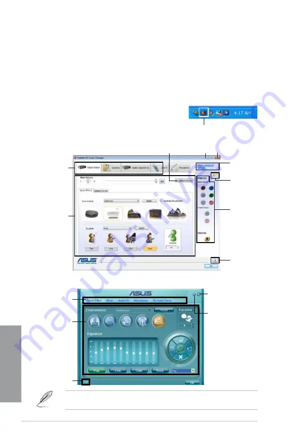
If the Realtek audio software is correctly installed, you will find 

the 

Realtek HD Audio Manager

 icon on the taskbar. Double-

click on the icon to display the Realtek HD Audio Manager.

Realtek HD Audio Manager

A. 

Realtek HD Audio Manager for Windows

®

 Vista™

Control 

settings 

window

Configuration 

option tabs 

Information 

button

Exit button

Minimize button

Device 

advanced 

settings

Connector 

settings

Analog 

and digital 

connector 

status

Set default device button

Control settings 

window

Configuration 

options 

Information button

Exit button

Minimize button

B. 

Realtek HD Audio Manager for Windows XP

Summary of Contents for M4A79T Deluxe U3S6

Page 1: ...Motherboard M4A79T Deluxe ...

Page 2: ...MERCHANTABILITY OR FITNESS FOR A PARTICULAR PURPOSE IN NO EVENT SHALL ASUS ITS DIRECTORS OFFICERS EMPLOYEES OR AGENTS BE LIABLE FOR ANY INDIRECT SPECIAL INCIDENTAL OR CONSEQUENTIAL DAMAGES INCLUDING DAMAGES FOR LOSS OF PROFITS LOSS OF BUSINESS LOSS OF USE OR DATA INTERRUPTION OF BUSINESS AND THE LIKE EVEN IF ASUS HAS BEEN ADVISED OF THE POSSIBILITY OF SUCH DAMAGES ARISING FROM ANY DEFECT OR ERROR ...

Page 3: ...yout contents 2 3 2 2 3 Placement direction 2 4 2 2 4 Screw holes 2 4 2 3 Central Processing Unit CPU 2 5 2 3 1 Installing the CPU 2 5 2 3 2 Installing the heatsink and fan 2 7 2 4 System memory 2 10 2 4 1 Overview 2 10 2 4 2 Memory configurations 2 11 2 4 3 Installing a DIMM 2 15 2 4 4 Removing a DIMM 2 15 2 5 Expansion slots 2 16 2 5 1 Installing an expansion card 2 16 2 5 2 Configuring an expan...

Page 4: ...r 3 8 3 3 9 General help 3 8 3 4 Main menu 3 9 3 4 1 Primary IDE Master Slave SATA 1 5 ESATA 3 9 3 4 2 Storage Configuration 3 11 3 4 3 System Information 3 12 3 5 Ai Tweaker menu 3 12 3 5 1 AI Overclocking Tuner Auto 3 12 3 5 2 CPU Ratio Auto 3 13 3 5 3 FSB Frequency XXX 3 13 3 5 4 PCIE Frequency XXX 3 13 3 5 5 DRAM Frequency 800MHz 3 13 3 5 6 CPU NB Frequency Auto 3 13 3 5 7 HT Link Speed Auto 3...

Page 5: ...iority 3 28 3 8 2 Boot Settings Configuration 3 29 3 8 3 Security 3 30 3 9 Tools menu 3 32 3 9 1 ASUS EZ Flash 2 3 32 3 9 2 Express Gate 3 32 3 9 3 ASUS O C Profile 3 33 3 9 4 AI NET 2 3 34 3 10 Exit menu 3 35 Chapter 4 Software support 4 1 Installing an operating system 4 1 4 2 Support DVD information 4 1 4 2 1 Running the support DVD 4 1 4 2 2 Obtaining the software manuals 4 2 4 3 Software info...

Page 6: ...ng a RAID SATA driver disk in Windows 4 20 Chapter 5 ATI CrossFireX technology support 5 1 ATI CrossFireX technology 5 1 5 1 1 Requirements 5 1 5 1 2 Before you begin 5 1 5 2 Installing CrossFireX graphics cards 5 2 5 2 1 Dual CrossFireX installation 5 2 5 2 2 Triple CrossFireX installation 5 3 5 2 3 Quad CrossFireX installation 5 4 5 3 Software information 5 5 5 3 1 Installing the device drivers ...

Page 7: ...ause harmful interference to radio or television reception which can be determined by turning the equipment off and on the user is encouraged to try to correct the interference by one or more of the following measures Reorient or relocate the receiving antenna Increase the separation between the equipment and receiver Connect the equipment to an outlet on a circuit different from that to which the...

Page 8: ...efore installing the motherboard and adding devices on it carefully read all the manuals that came with the package Before using the product make sure all cables are correctly connected and the power cables are not damaged If you detect any damage contact your dealer immediately To avoid short circuits keep paper clips screws and staples away from connectors slots sockets and circuitry Avoid dust ...

Page 9: ...OS Setup menus Detailed descriptions of the BIOS parameters are also provided Chapter 4 Software support This chapter describes the contents of the support DVD that comes with the motherboard package and the software Chapter 5 ATI CrossFireX support This chapter describes the ATI CrossFireX feature and shows the graphics card installation procedures Where to find more information Refer to the foll...

Page 10: ...ey1 Key2 Key3 If you must press two or more keys simultaneously the key names are linked with a plus sign Example Ctrl Alt D Command Means that you must type the command exactly as shown then supply the required item or value enclosed in brackets Example At the DOS prompt type the command line afudos M4a79tdlx ROM DANGER WARNING Information to prevent injury to yourself when trying to complete a t...

Page 11: ...VL Qualified Vendors Lists Expansion slots 4 x PCI Express 2 0 x16 slots with ATICrossFireX support dual x16 triple x16 x8 x8 or quad x8 modes 2 x PCI 2 2 slots Multi GPU support Supports ATICrossFireX technology up to Quad CrossFireX Storage SB750 chipset 1 x Ultra DMA 133 100 66 for up to 2 PATA devices 5 x SATA3 Gb s ports supporting RAID 0 1 5 10 and JBOD 1 x eSATA3 Gb s port SATAon the go LAN...

Page 12: ...ymer Cpacitors VRM 5000hrs lifespan 105 C 500 000hrs 65 C ASUS MyLogo 2 AMD OverDrive Support Advanced cooling system is required when advanced overclocking functions of AMD OverDrive are enabled ASUS exclusive overclocking features Intelligent overclocking tools AI Overclocking Intelligent CPU Frequency Tuner TurboV Turbo Key Precision Tweaker 2 vCore Adjustable CPU voltage at 0 0125V increment v...

Page 13: ... connector 2 x Chassis Fan connectors 1 x Power Fan connector 1 x IEEE1394a connector Front panel audio connector 1 x S PDIF Out Header Chassis Intrusion connector CD audio in 24 pin ATX Power connector System Panel Q Connector 8 pin ATX 12V Power connector 1 x Power on switch 1 x Reset switch BIOS features 8 Mb Flash ROM AMI BIOS PnP DMI 2 0 SM BIOS 2 5 ACPI 2 0a ASUS EZ Flash 2 CrashFree BIOS 2 ...

Page 14: ...xiv ...

Page 15: ...t below 1 2 Package contents Check your motherboard package for the following items ASUS M4A79T Deluxe Motherboard 1 x Multi functional module 2 port USB 2 0 and 1 port IEEE 1394a 2 x ASUS CrossFire bridge cables 5 x Serial ATA signal cables 1 x Ultra DMA 133 100 66 cable 1 x ASUS Q Shield I O shield UserManual 1 x ASUS Q Connector Kit User Guide Support DVD If any of the above items is damaged or...

Page 16: ...ering shading and texture settings Adjust your display configurations experiment with the advanced 3D settings and check the effects with a real time 3D rendered previews within ATI Catalyst Control Center DDR3 1600 O C support This motherboard supports DDR3 1600 O C that provides faster data transfer rate and more bandwith to increase memory computing efficiency enhancing system performance in 3D...

Page 17: ... s Restriction on the use of Hazardous Substances RoHS to safeguard consumers health while minimizing the impact of the environment ASUS EPU The ASUS EPU Energy Processing Unit provides total system power management by detecting current PC loadings and intelligently moderating power usage for critical PC components in real time helping save power and money AI Nap With AI Nap the system can continu...

Page 18: ...and efficient operation ASUS EZ DIY ASUS EZ DIY feature collection provides you easy ways to install computer components update the BIOS or back up your favorite settings ASUS Q Shield The specially designed ASUS Q Shield does without the usual fingers making it convenient and easy to install With better electric conductivity it ideally protects your motherboard against static electricity and shie...

Page 19: ...iendly interface makes overclock with just a few clicks away Moreover the ASUS OC profiles in TurboV provides the best O C settings in different scenarios Turbo Key ASUS Turbo Key allows the user to turn the PC power button into a physical overclocking button After the easy setup Turbo Key can boost performances without interrupting ongoing work or games with just one touch Precision Tweaker 2 All...

Page 20: ...1 6 Chapter 1 Product Introduction Chapter 1 ...

Page 21: ...object or a metal object such as the power supply case to avoid damaging them due to static electricity Hold components by the edges to avoid touching the ICs on them Whenever you uninstall any component place it on a grounded antistatic pad or in the bag that came with the component Before you install or remove any component ensure that the ATX power supply is switched off or the power cord is de...

Page 22: ...2 2 Chapter 2 Hardware information Chapter 2 2 2 1 Motherboard layout Refer to 2 8 Connectors for more information about rear panel connectors and internal connectors 2 2 Motherboard overview ...

Page 23: ...29 7 Clear RTC RAM 3 pin CLRTC 2 20 8 System panel connector 20 8 pin PANEL 2 36 9 Chassis intrusion connector 4 1 pin CHASSIS 2 33 10 Reset switch 2 22 11 Power on switch 2 22 12 USB connectors 10 1 pin USB78 USB910 USB1112 2 30 13 CPU overvoltage setting 3 pin OV_CPU 2 21 14 Serial port connector 10 1 pin COM1 2 31 15 Floppy disk drive connector 34 1 pin FLOPPY 2 27 16 IEEE 1394a port connector ...

Page 24: ... the correct orientation The edge with external ports goes to the rear part of the chassis as indicated in the image below 2 2 4 Screw holes Place nine 9 screws into the holes indicated by circles to secure the motherboard to the chassis DO NOT overtighten the screws Doing so can damage the motherboard Place this side towards the rear of the chassis ...

Page 25: ...e AM3 socket has a different pinout from the AM2 AM2 socket Make sure you use a CPU designed for the AM3 socket The CPU fits in only one correct orientation DO NOT force the CPU into the socket to prevent bending the connectors on the socket and damaging the CPU Make sure that the socket lever is lifted up to a 90 angle Otherwise the CPU will not fit in completely 2 Press the lever sideways to unl...

Page 26: ... tab to indicate that it is locked Gold triangle Small triangle 6 Apply several drops of thermal paste to the exposed area of the CPU that the heatsink will be in contact with ensuring that it is spread in an even thin layer Some heatsinks come with pre applied thermal paste If so skip this step The Thermal Interface Material is toxic and inedible DO NOT eat it If it gets into your eyes or touches...

Page 27: ...or the CPU heatsink and the retention mechanism If the instructions in this section do not match the CPU documentation follow the latter The retention module base is already installed on the motherboard upon purchase You do not have to remove the retention module base when installing the CPU or installing other motherboard components If you purchased a separate CPU heatsink and fan assembly make s...

Page 28: ...et to the retention module base A clicking sound denotes that the retention bracket is in place 4 Push down the retention bracket lock on the retention mechanism to secure the heatsink and fan to the module base Ensure that the fan and heatsink assembly perfectly fits the retention mechanism module base otherwise you cannot snap the retention bracket in place ...

Page 29: ... is in place connect the CPU fan cable to the connector on the motherboard labeled CPU_FAN Do not forget to connect the CPU fan connector Hardware monitoring errors can occur if you fail to plug this connector This connector is backward compatible with old 3 pin CPU fan ...

Page 30: ...sions as a DDR2 DIMM but is notched differently to prevent installation on a DDR2 DIMM socket DDR3 modules are developed for better performance with less power consumption The figure illustrates the location of the DDR3 DIMM sockets Recommended memory configurations One DIMM You may install one memory module in any slot as a single channel operation Two DIMMs dual channel operation Four DIMMs dual...

Page 31: ...the same vendor Due to the memory address limitation on 32 bit Windows OS when you install 4GB or more memory on the motherboard the actual usable memory for the OS can be about 3GB or less For effective use of memory we recommend that you install a 64 bit Windows OS when having 4GB or more memory installed on the motherboard This motherboard does not support DIMMs made up of 256 megabit Mb chips ...

Page 32: ...00CL7D 4GBPI 4096MB Kit of 2 DS N A Heat Sink Package 7 7 7 18 1333 9 9 9 24 1 9 G Skill F3 12800CL8T 6GBHK XMP 6144MB Kit of 3 DS N A Heat Sink Package 8 8 8 21 1333 8 8 8 21 1 6 1 65 G SKILL F3 12800CL9T 6GBNQ 6144MB Kit of 3 DS N A Heat Sink Package 9 9 9 24 1601 9 9 9 24 1 5 1 6 KINGSTON KHX12800D3LLK3 3GX XMP 3072MB Kit of 3 SS N A Heat Sink Package 1333 9 9 9 24 1 65 KINGSTON KHX12800D3K2 4G...

Page 33: ... N A Heat Sink Package 9 9 9 24 1333 9 9 9 24 1 5 KINGMAX FLFD45F B8EE9 1024MB SS ELPIDA J1108BASE DJ E 1333 9 9 9 24 KINGSTON KVR1333D3N9 1G 1024MB SS ELPIDA J1108BASE DJ E 1333 9 9 9 24 1 5 KINGSTON KVR1333D3N9 2G 2048MB DS ELPIDA J1108BASE DJ E 1333 9 9 9 24 1 5 MICRON MT16JTF25664AY 1G4BYES 2048MB DS MICRON Z9HWR 1333 9 9 9 24 OCZ OCZ3RPX1333EB2GK 1024MB SS N A Heat Sink Package 1066 6 5 5 20 ...

Page 34: ...N A Heat Sink Package 6 6 6 15 1 65 Hynix HMT112U6AFP8C G7N0 1024MB SS HYNIX H5TQ1G83AFPG7C 7 Hynix HYMT112U64ZNF8 G7 1024MB SS HYNIX HY5TQ1G831ZNFP G7 7 Hynix HMT125U6AFP8C G7N0 2048MB DS HYNIX H5TQ1G83AFPG7C 7 Hynix HYMT125U64ZNF8 G7 2048MB DS HYNIX HY5TQ1G831ZNFP G7 7 KINGSTON KVR1066D3N7 1G 1024MB DS ELPIDA J5308BASE AC E 1 5 KINGSTON KVR1066D3N7 2G 2048MB DS SAMSUNG K4B1G0846C ZCF8 1 5 MICRON...

Page 35: ...retaining clips snap back in place and the DIMM is properly seated Make sure to unplug the power supply before adding or removing DIMMs or other system components Failure to do so may cause severe damage to both the motherboard and the components A DIMM is keyed with a notch so that it fits in only one direction DO NOT force a DIMM into a socket to avoid damaging the DIMM Unlocked retaining clip 1...

Page 36: ...ot 5 Secure the card to the chassis with the screw you removed earlier 6 Replace the system cover 2 5 2 Configuring an expansion card After installing the expansion card configure it by adjusting the software settings 1 Turn on the system and change the necessary BIOS settings if any See Chapter 3 for information on BIOS setup 2 Assign an IRQ to the card Refer to the tables on the next page 3 Inst...

Page 37: ...red USB controller 1 shared USB controller 2 shared USB controller 3 shared USB controller 4 shared USB 2 0 controller shared HD audio shared Onboard SATA shared IRQ Priority Standard function 0 1 System Timer 1 2 Keyboard Controller 2 Redirect to IRQ 9 4 12 Communications Port COM1 5 13 IRQ Holder for PCI Steering 6 14 Floppy Disk Controller 7 15 Reserved 8 3 System CMOS Real Time Clock 9 4 IRQ H...

Page 38: ...ards that comply with the PCI Express specifications With four graphics cards installed the motherboard can enable quad display Refer to the figure below for the location of the slots PCI slot PCI Express x 16_2 slot black at max x8 link Primary PCI Express x16_3 slot blue at max x16 link PCI Express x 16_4 slot black at max x8 link PCI slot Primary PCI Express x16_1 slot blue at max x16 link Befo...

Page 39: ... motherboard connector labeled CHA_FAN1 2 for better thermal environment See page 2 29 for the connector location When using one graphics card and a x4 PCIe card at the same time install them to the blue slots When using two graphics card install them to the blue slots If you install two graphics cards to the blue slots and use other x4 PCIe cards simultaneously the x4 PCIe cards will downgrade to...

Page 40: ...mputer 4 Hold down the Del key during the boot process and enter BIOS setup to re enter data Except when clearing the RTC RAM never remove the cap on CLRTC jumper default position Removing the cap will cause system boot failure If the steps above do not help remove the onboard battery and move the jumper again to clear the CMOS RTC RAM data After the CMOS clearance reinstall the battery You do not...

Page 41: ...d in 3 5 Ai Tweaker menu first to adjust the desired CPU performance Ensure that your system functions well under the highest BIOS voltage setting before you change the setting of this jumper Refer to 3 5 Ai Tweaker menu for more information about the CPU overvoltage setting DO NOT set the OV_CPU jumper to pins 1 2 when you install a new CPU and have not booted for the first time Doing so may caus...

Page 42: ...d switches allow you to power on or reboot system quickly and conveniently when you want to fine tune performance on a bare or open case system 1 Power on switch Press the power on switch to wake power up the system 2 Reset switch Press the reset switch to reboot the system ...

Page 43: ...F Out port 2 Coaxial S PDIF Out port 8 External SATA port 3 IEEE 1394a port 9 USB 2 0 ports 3 and 4 4 LAN RJ 45 port 10 USB 2 0 ports 1 and 2 5 PS 2 keyboard port purple 11 Audio I O ports 6 USB 2 0 ports 5 and 6 To use hot plug set the OnChip SATA Type in the BIOS settings to AHCI mode See section 3 4 2 Storage Configuration for details ...

Page 44: ...nt Speaker Out Front Speaker Out Front Speaker Out Pink Mic In Mic In Mic In Mic In Orange Center Subwoofer Center Subwoofer Black Rear Speaker Out Rear Speaker Out Rear Speaker Out Gray Side Speaker Out LAN port LED indications Right LED Left LED LAN port Status Left LED Right LED OFF OFF OFF 10 Mbps connection Orange blinking during data activity OFF 100 Mbps connection OFF Orange blinking durin...

Page 45: ...ASUS M4A79T Deluxe 2 25 Chapter 2 Connect to Stereo Speakers Connect to 2 1 channel Speakers Connect to 4 1 channel Speakers ...

Page 46: ...2 26 Chapter 2 Hardware information Chapter 2 Connect to 5 1 channel Speakers Connect to 7 1 channel Speakers ...

Page 47: ...floppy disk drive Pin 5 on the connector is removed to prevent incorrect cable connection when using a FDD cable with a covered Pin 5 The floppy disk drive cable is purchased separately 2 Digital audio connector 4 1 pin SPDIF_OUT This connector is for an additional Sony Philips Digital Interface S PDIF port s Connect the S PDIF Out module cable to this connector then install the module to a slot o...

Page 48: ...nts incorrect insertion when you connect the IDE cable Use the 80 conductor IDE cable for Ultra DMA 133 100 66 IDE devices If any device jumper is set as Cable Select make sure all other device jumpers have the same setting 3 IDE connector 40 1 pin PRI_IDE The onboard IDE connector is for the Ultra DMA 133 100 66 signal cable There are three connectors on each Ultra DMA 133 100 66 signal cable blu...

Page 49: ...on through the onboard AMD SB750 controller These connectors are set to IDE by default If you intend to create a Serial ATA RAID set using these connectors set the Onchip SATA Type item in the BIOS to RAID Install the Windows XP Service Pack 1 or later version before using Serial ATA For detailed instructions on how to configure RAID 0 RAID 1 RAID 5 and RAID 10 refer to the RAID manual in the supp...

Page 50: ...B 2 0 specification that supports up to 480 Mbps connection speed Never connect a 1394 cable to the USB connectors Doing so will damage the motherboard You can connect the front panel USB cable to the ASUS Q Connector USB blue first and then install the Q Connector USB to the USB connector onboard if your chassis supports front panel USB ports 6 Optical drive audio connector 4 pin CD These connect...

Page 51: ...dule to a slot opening at the back of the system chassis Never connect a USB cable to the IEEE 1394a connector Doing so will damage the motherboard 8 Serial port connector 10 1 pin COM1 This connector is for a serial COM port Connect the serial port module cable to this connector then install the module to a slot opening at the back of the system chassis The COM module is purchased separately ...

Page 52: ...e black wire of each cable matches the ground pin of the connector Do not forget to connect the fan cables to the fan connectors Insufficient air flow inside the system may damage the motherboard components These are not jumpers Do not place jumper caps on the fan connectors Only the CPU_FAN CHA_FAN 1 and CHA_FAN 2 connectors support the ASUS Q Fan 2 feature If you install two VGA cards we recomme...

Page 53: ...ensor or switch cable to this connector The chassis intrusion sensor or switch sends a high level signal to this connector when a chassis component is removed or replaced The signal is then generated as a chassis intrusion event By default the pin labeled Chassis Signal and Ground are shorted with a jumper cap Remove the jumper caps only when you intend to use the chassis intrusion detection featu...

Page 54: ...upply requirement for your system refer to the Recommended Power Supply Wattage Calculator at http support asus com PowerSupplyCalculator PSCalculator aspx SLanguage en us for details The ATX 12 V Specification 2 0 compliant 1000W PSU has been tested to support the motherboard power requirements with the following configuration CPU AMD Phenom 9950 Memory 1024 MB DDR3 x4 Graphics card PCI Express x...

Page 55: ... module cable to this connector We recommend that you connect a high definition front panel audio module to this connector to avail of the motherboard s high definition audio capability If you want to connect a high definition front panel audio module to this connector set the Front Panel Type item in the BIOS setup to HD if you want to connect an AC 97 front panel audio module to this connector s...

Page 56: ...stem warning speaker 4 pin SPEAKER This 4 pin connector is for the chassis mounted system warning speaker The speaker allows you to hear system beeps and warnings ATX power button soft off button 2 pin PWRSW This connector is for the system power button Pressing the power button turns the system on or puts the system in sleep or soft off mode depending on the BIOS settings Pressing the power switc...

Page 57: ... the detailed pin definitions and then match them to their respective front panel cable labels The labels on the front panel cables may vary depending on the chassis model 2 Install the ASUS Q Connector to the system panel connector making sure the orientation matches the labels on the motherboard 3 The front panel functions are now enabled The figure shows the Q Connector is properly installed on...

Page 58: ...ests are running the BIOS beeps see BIOS beep codes table below or additional messages appear on the screen If you do not see anything within 30 seconds from the time you turned on the power the system may have failed a power on test Check the jumper settings and connections or call your retailer for assistance 7 At power on hold down the Delete key to enter the BIOS Setup Follow the instructions ...

Page 59: ...r to the corresponding sections for details on these utilities Save a copy of the original motherboard BIOS file to a floppy disk or USB flash disk in case you need to restore the BIOS in the future Copy the original motherboard BIOS using the ASUS Update utility Inappropriate settings of the BIOS may result in system s instability or failure to boot We strongly recommend that you change the BIOS ...

Page 60: ...age ASUS Update requires an Internet connection either through a network or an Internet Service Provider ISP Installing ASUS Update To install ASUS Update 1 Place the support DVD in the optical drive The Drivers menu appears 2 Click the Utilities tab then click Install ASUS Update VX XX XX 3 The ASUS Update utility is copied to your system Quit all Windows applications before you update the BIOS u...

Page 61: ...s 2 Select Update BIOS from a file from the dropdown menu then click Next M4a79tdlx M4a79tdlx COM Ensure to load the BIOS default settings to ensure system compatibility and stability Select the Load Setup Defaults item under the Exit menu See section 3 10 Exit Menu for details 5 Follow the onscreen instructions to complete the update process The ASUS Update utility is capable of updating itself t...

Page 62: ...nment a From the Windows desktop click Start My Computer b Select the 3 1 2 Floppy Drive icon c Click File from the menu then select Format A Format 3 1 2 Floppy Disk window appears d Select Create an MS DOS startup disk from the format options field then click Start Windows Vista environment a From the Windows desktop click Computer b Right click Floppy Disk Drive then click Format to display the...

Page 63: ... BIOS ROM Utility V3 34 Current ROM Update ROM A Note Enter Select or Load Tab Switch V Drive Info Up Down Home End Move B Backup Esc Exit FLASH TYPE MXIC 25L8005 PATH A BOARD M4A79T Deluxe VER 0115 DATE 12 08 2008 BOARD Unknown VER Unknown DATE Unknown 2 Press Tab to switch between drives until the correct BIOS file is found When the correct BIOS file is found EZ Flash 2 performs the BIOS update ...

Page 64: ...S file to the floppy disk or optical drive 3 The utility displays the following message and automatically checks the floppy disk or support DVD for the BIOS file 4 Restart the system after the utility completes the updating process When found the utility reads the BIOS file and starts flashing the corrupted BIOS file Bad BIOS checksum Starting BIOS recovery Checking for floppy Bad BIOS checksum St...

Page 65: ...ls If the system fails to boot after changing any BIOS setting try to clear the CMOS and reset the motherboard to the default value See section 2 6 Jumpers for details 3 3 1 BIOS menu screen Select Screen Select Item Change Field Tab Select Field F1 General Help F10 Save and Exit ESC Exit v02 61 C Copyright 1985 2008 American Megatrends Inc BIOS SETUP UTILITY Main Ai Tweaker Advanced Power Boot To...

Page 66: ...3 3 6 Configuration fields These fields show the values for the menu items If an item is user configurable you can change the value of the field opposite the item You cannot select an item that is not user configurable A configurable field is enclosed in brackets and is highlighted when selected To change the value of a field select it then press Enter to display a list of options Refer to 3 3 7 P...

Page 67: ...System Time 10 55 25 System Date Tue 12 09 200 8 Legacy Diskette A 1 44M 3 5 in Language English Primary IDE Master Not Detected Primary IDE Slave Not Detected SATA1 HDT722516DLA380 SATA2 Not Detected SATA3 Not Detected SATA4 Not Detected SATA5 Not Detected ESATA Not Detected Storage Configuration System Information Use ENTER TAB or SHIFT TAB to select a field Use or to configure the System Time 3...

Page 68: ...o Enables or disables data multi sectors transfers Auto When set to Auto the data transfer from and to the device occurs in multiple sectors at a time if the device supports multi sector transfer feature Disabled When set to Disabled the data transfer from and to the device occurs one sector at a time PIO Mode Auto Auto Allows automatic selection of the PIO Programmed input output modes which corr...

Page 69: ...ou want the SATA hard disk drives to use the AHCI Advanced Host Controller Interface The AHCI allows the onboard storage driver to enable advanced Serial ATA features that increases storage performance on random workloads by allowing the drive to internally optimize the order of commands When this item is set to AHCI only SATA connectors 1 4 can be detected Ensure that you ve installed the AHCI dr...

Page 70: ...to DRAM Frequency Control Auto HT Link Speed Auto Please key in numbers directly Processor Voltage Auto CPU NB Voltage Auto CPU VDDA Voltage Auto DRAM Voltage Auto HT Voltage Auto NB Voltage Auto NB 1 8V Voltage Auto SB Voltage Auto CPU Spread Spectrum Enabled PCIE Spread Spectrum Enabled 3 5 1 AI Overclocking Tuner Auto Allows you to select the CPU overclocking options to achieve the desired CPU ...

Page 71: ...Allows you to set the DDR3 operating frequency Configuration options 1800MHz 1600MHz 1333MHz 1066MHz The DRAM Frequency configuration options vary with the FSB Frequency settings Selecting a very high DRAM frequency may cause the system to become unstable If this happens revert to the default setting 3 5 6 CPU NB Frequency Auto Allows you to select the CPU NB frequency multiplier Configuration opt...

Page 72: ...Disabled Enabled DCT Unganged Mode Always Configuration options Auto Always Power Down Enable Disabled Enables or disables the DDR power down mode Configuration options Disabled Enabled Power Down Mode Channel Allows you to set the DDR power down mode This item appears only when you enable the previous item Configuration options Channel Chip Select Page Smashing Disabled S W Control of Page Smashi...

Page 73: ...LK 7 CLK TRC Auto Configuration options Auto 11 CLK 12 CLK 13 CLK 41 CLK TWR Auto Configuration options Auto 5 CLK 6 CLK 7 CLK 8 CLK 10 CLK 12 CLK TRRD Auto Configuration options Auto 4 CLK 5 CLK 6 CLK 7 CLK DRAM 2nd Information 5 2 4 45 3 3 90 0 TRWTTO Auto Configuration options Auto 3 CLK 4 CLK 5 CLK 17 CLK TWRRD Auto Configuration options Auto 2 CLK 3 CLK 4 CLK 10 CLK 3 5 9 DRAM Timing Configur...

Page 74: ...25x 1 5x 2x DCT0 MEMCLK drive strength Auto DCT1 MEMCLK drive strength Auto Configuration options Auto 0 75x 1x 1 25x 1 5x DCT0 Data drive strength Auto DCT1 Data drive strength Auto Configuration options Auto 0 75x 1x 1 25x 1 5x DCT0 DQS drive strength Auto DCT1 DQS drive strength Auto Configuration options Auto 0 75x 1x 1 25x 1 5x DCT0 Processor on die terminat Auto DCT1 Processor on die termina...

Page 75: ...ge from 2 50V to 2 80V with a 0 10V interval 3 5 13 DRAM Voltage Auto Allows you to select the DDR3 reference voltage The values range from 1 50V to 2 50V with a 0 02V interval 3 5 14 HT Voltage Auto Allows you to select the HyperTransport voltage The values range from 1 20V to 1 50V with a 0 02V interval 3 5 15 NB Voltage Auto Allows you to select the Northbridge voltage The values range from 1 1...

Page 76: ...e and Exit ESC Exit v02 61 C Copyright 1985 2008 American Megatrends Inc CPU Configuration Module Version 14 07 AGESA Version 6 0 7 3 AMD Phenom tm 8600 Triple Core Processor Revision B2 Cache L1 384KB Cache L2 1536KB Cache L3 2MB Speed 2200MHz NB Clk 1800MHz Able to Change Freq Yes uCode Patch Level 0x100008D GART Error Reporting Disabled Microcode Updation Enabled Secure Virtual Machine Mode Ena...

Page 77: ...the AMD Cool n Quiet function ACPI SRAT Table Enabled Allows you to enable or disable the building of ACPI SRAT Table Disabled Disables the building of ACPI SRAT Table Enabled Enables the building of ACPI SRAT Table C1E Support Disabled Allows you to enable or disable the Enhanced Halt State support Disabled Disables the the Enhanced Halt State support Enabled Enables the the Enhanced Halt State s...

Page 78: ...tem integrity DRAM SCRUB REDIRECT Disabled Disabled Disables this function Enabled Allows the system to correct the DRAM ECC errors immediately when they occur 4 Bit ECC Mode Disabled Disabled Disables the CHIPKILL ECC mode Enabled Enables the CHIPKILL ECC mode Advanced Chipset Settings NorthBridge Configuration RD790 Configuration Options for NB BIOS SETUP UTILITY Advanced North Bridge Chipset Co...

Page 79: ...42 00ms 84 00ms Set the ECC options for cache and dram scrubbing RD790 Configuration RD790 Configuration PCI Express Configuration BIOS SETUP UTILITY Advanced PCI Express Configuration PCI Express Configuration GFX Dual Slot Configuration Auto GFX2 Dual Slot Configuration Auto Peer to Peer among GFX GFX2 Disabled GPP Slots Power Limit W 25 Auto Enable Disabled BIOS SETUP UTILITY Advanced GFX Dual ...

Page 80: ...I Output Sets to HDMI Output for HDMI audio output Onboard LAN Enabled Enabled Enables the onboard LAN controller Disabled Disables the onboard controller The following item appears only when you set the Onboard LAN item to Enabled Onboard LAN Boot ROM Disabled Enabled Enables the onboard LAN Boot ROM Disabled Disables the onboard LAN Boot ROM Firewire 1394 Enabled Enabled Enables the onboard 1394...

Page 81: ... Disabled Disables the controllers The following items appear only when you set USB Support to Enabled Legacy USB Support Enabled Auto Allows the system to detect the presence of USB devices at startup If detected the USB controller legacy mode is enabled If no USB device is detected the legacy USB support is disabled Enabled Enables the support for USB devices on legacy operating systems OS Disab...

Page 82: ...NO lets the BIOS configure all the devices in the system YES lets the operating system configure Plug and Play PnP devices not required for boot if your system has a Plug and Play operating system BIOS SETUP UTILITY Advanced Plug And Play O S No Yes When set to Yes and if you install a Plug and Play operating system the operating system configures the Plug and Play devices not required for boot No...

Page 83: ...nvokes VGA BIOS POST on S3 STR resume 3 7 3 ACPI 2 0 Support Disabled Disabled When set to Disabled the system will not add additional tables as per ACPI 2 0 specifications Enabled When set to Enabled the system adds additional tables as per ACPI 2 0 specifications 3 7 4 ACPI APIC Support Enabled Disabled When set to Disabled the system disable the Advanced Configuration and Power Interface ACPI s...

Page 84: ...S 2 mouse This feature requires an ATX power supply that provides at least 1A on the 5VSB lead Power On By Ring Disabled Disabled The computer could not be powered up when the external modem receives a call while the computer is in Soft off mode Enabled The computer could be powered up when the external modem receives a call while the computer is in Soft off mode The computer cannot receive or tra...

Page 85: ...item CPU Q Fan Function Disabled Allows you to enable or disable the CPU Q Fan control feature Disabled Disables the CPU Q Fan control feature Enabled Enables the CPU Q Fan control feature The following two items appear only when you set CPU Q Fan Function to Enabled Select Fan Type PWR Fan Allows you to set the appropriate CPU fan type PWR Fan Sets to PWR Fan when using a 4 pin CPU fan DC Fan Set...

Page 86: ... Item Enter Go to Sub Screen F1 General Help F10 Save and Exit ESC Exit v02 61 C Copyright 1985 2008 American Megatrends Inc BIOS SETUP UTILITY Main Ai Tweaker Advanced Power Boot Tools Exit Boot Settings Boot Device Priority Boot Settings Configuration Security Specifies the Boot Device Boot Priority sequence A virtual floppy disk drive Floppy Drive B may appear when you set the CD ROM drive as t...

Page 87: ...M messages will be forced to display during the boot sequence Keep Current The third party ROM messages will be displayed only if the third party manufacturer had set the add on device to do so Bootup Num Lock On Allows you to select the power on state for the NumLock Off Sets the power on state of the NumLock to Off On Sets the power on state of the NumLock to On Wait For F1 If Error Enabled Disa...

Page 88: ...irm the password when prompted The message Password Installed appears after you successfully set your password To change the supervisor password follow the same steps as in setting a user password To clear the supervisor password select the Change Supervisor Password then press Enter The message Password Uninstalled appears If you forget your BIOS password you can clear clear it by erasing the CMO...

Page 89: ...in the Setup utility Change User Password Select this item to set or change the user password The User Password item on top of the screen shows the default Not Installed After you set a password this item shows Installed To set a User Password 1 Select the Change User Password item and press Enter 2 On the password box that appears type a password composed of at least six letters and or numbers th...

Page 90: ...CD DISC read only 3 9 1 ASUS EZ Flash 2 Allows you to run ASUS EZ Flash 2 When you press Enter a confirmation message appears Use the left right arrow key to select between Yes or No then press Enter to confirm your choice For more details refer to section 3 2 3 ASUS EZ Flash 2 utility ASUSTek EZ Flash 2 BIOS ROM Utility V3 34 Current ROM Update ROM A Note Enter Select or Load Tab Switch V Drive I...

Page 91: ...eptable BIOS SETUP UTILITY Tools Sets countdown duration that the system waits at the Express Gate s first screen before starting Windows or other installed OS Choose Prompt User to stay at the first screen of Express Gate for user action Configuration options Prompt User 1 second 3 seconds 5 seconds 10 seconds 15 seconds 20 seconds 30 seconds Reset User Data No Allows you to clear Express Gate s ...

Page 92: ...t failure We recommend that you update the BIOS file only coming from the same memory CPU configuration and BIOS version Only the CMO file can be loaded ASUSTek O C Profile Utility V1 34 3 9 4 AI NET 2 Check Realtek LAN Cable Disabled Enables or disables checking of the Realtek LAN cable during the Power On Self Test POST It takes 3 to 10 seconds to diagnose the LAN cable Disabled BIOS will not ch...

Page 93: ...the PC is turned off When you select this option a confirmation window appears Select Ok to save changes and exit If you attempt to exit the Setup program without saving your changes the program prompts you with a message asking if you want to save your changes before exiting Press Enter to save the changes while exiting Exit Discard Changes Select this option only if you do not want to save the c...

Page 94: ...3 36 Chapter 3 BIOS setup Chapter 3 ...

Page 95: ... want to install Motherboard settings and hardware options vary Use the setup procedures presented in this chapter for reference only Refer to your OS documentation for detailed information Ensure that you install the Windows XP Service Pack 2 or later versions before installing the drivers for better compatibility and system stability The contents of the support DVD are subject to change at any t...

Page 96: ...iles are in Portable Document Format PDF Install the Adobe Acrobat Reader from the Utilities menu before opening the files 1 Click the support DVD icon 2 The support DVD contents are displayed in graphical format Double click the Manual folder 3 Double click the folder of your selected manual The screenshots in this section are for reference only The actual software manuals containing in the suppo...

Page 97: ... 4 Reboot your computer and set your Power Option Properties depending on your operating system 4 3 Software information Most of the applications in the support DVD have wizards that will conveniently guide you through the installation View the online help or readme file that came with the software application for more information Launching the Cool n Quiet software 1 Install Cool n Quiet software...

Page 98: ... users plug and play convenience Follow the installation wizard to install the Realtek Audio Driver from the support CD DVD that came with the motherboard package If the Realtek audio software is correctly installed you will find the Realtek HD Audio Manager icon on the taskbar Double click on the icon to display the Realtek HD Audio Manager Realtek HD Audio Manager A Realtek HD Audio Manager for ...

Page 99: ...VD 2 Launch PC Probe II by clicking Start All Programs ASUS PC Probe II PC Probe II v1 xx xx The PC Probe II main window appears 3 The PC Probe II icon appears in the Windows notification area Click this icon to close or restore the application PC Probe II main window Refer to the software manual in the support DVD or visit the ASUS website at www asus com for detailed software configuration Butto...

Page 100: ... ports are NOT supported See chapter 2 for the exact location of the onboard SATA ports Ensure to install ASUS Express Gate from the motherboard support DVD before you start using the utility ASUS Express Gate SSD requires no installation ASUS Express Gate supports installation on SATA HDDs USB HDDs and Flash drives When installed on USB HDDs and Flash drives connect the drives to the motherboard ...

Page 101: ...n main window click this icon to restore the window Using AI Suite Click each utility button to launch the utility or click the Normal button to restore system default settings Click to launch each utility Click to restore default settings Click to open the monitor window that displays system information such as CPU temperature CPU voltage fan speed and CPU FSB frequency The screenshots in this se...

Page 102: ...t acceleration and overclocking ASUS EPU provides you with these modes to choose from Turbo Mode High Performance Mode When you select Auto Mode the system shifts modes automatically according to the current system status You can also configure advanced settings for each mode Launching EPU After installing EPU from the motherboard support DVD double click the EPU tray icon to launch the program EP...

Page 103: ... on the Windows OS taskbar and click the Q Fan 2 button on the AI Suite maIn window Click the drop down menu button and display the fan names Select CPU Q Fan 2 or CHASSIS Q Fan 2 Click the box of Enable Q Fan 2 to activate this function drop down list button Enable Q Fan 2 box Profile list appears after clicking the Enable Q Fan 2 box Click the drop down list button and select a profile Optimal m...

Page 104: ...er consumption and a more quiet system operation Using ASUS AI Nap 1 After installing ASUS AI Suite from the motherboard support DVD double click the ASUS Q Button icon in the Windows notification area to launch the Q Button user interface 2 Select AI Nap then click Apply to enable AI Nap function 3 Press the power button to enter AI Nap mode Press the power button again to exit AI Nap mode ...

Page 105: ...ing ASUS TurboV Launching ASUS TurboV 1 Install the ASUS TurboV utility from the motherboard support DVD 2 Click Start All Programs ASUS TurboV TurboV For advanced overclock ability adjust first the BIOS items and then proceed more detailed adjustments using TurboV Refer to the software manual in the support DVD or visit the ASUS website at www asus com for detailed software configuration Only AMD...

Page 106: ...ower button Select Turbo Key to boost system performance after pressing the power button 2 You can choose whether to show Q Button OSD and status by clicking the check boxes in the Setting section 3 You can decide the performance boost level by selecting Turbo Key Profile You can also load personal profiles saved in the ASUS TurboV utility The default is Rocket Mode See your motherboard manual for...

Page 107: ...to the entire system Use two new drives or use an existing drive and a new drive for this setup The new drive must be of the same size or larger than the existing drive RAID 5 stripes both data and parity information across three or more hard disk drives Among the advantages of RAID 5 configuration include better HDD performance fault tolerance and higher storage capacity The RAID 5 configuration ...

Page 108: ...nter the BIOS setup 3 In the Main Menu go to Storage Configuration and set the OnChip SATA Type item to RAID 3 Press F10 to save the changes and exit The RAID BIOS setup screens shown in this section are for reference only and may not exactly match the items on your screen 4 4 2 Installing Serial ATA hard disks The motherboard supports Serial ATA hard disk drives For optimal performance install id...

Page 109: ...et and partition Controller Configuration Shows the system resources configuration Press 1 2 3 or 4 to enter the option you need press ESC to exit the utility FastBuild tm Utility c 2004 2005 ATI Technology Inc View Drive Assignments 1 Define LD 2 Delete LD 3 Controller Configuration 4 Main Menu Press 1 4 to Select Option ESC Exit Keys Available AMD FastBuild Utility To enter the AMD FastBuild uti...

Page 110: ... Define LD Menu Up Down ESC Exit Enter Select Keys Available LD No RAID Mode Total Drv Capacity MB Status LD 1 RAID 0 2 xxxxxx Functional LD 2 LD 3 LD 4 LD 5 LD 6 LD 7 LD 8 FastBuild tm Utility c 2004 2005 ATI Technology Inc Up Down ESC Exit Space Change Option Ctrl Y Save Keys Available Define LD Menu Define LD Menu Channel ID Drive Model Capacity MB Assignment 1 Mas xxxxxxxxx xxxxxx Y 2 Mas xxxx...

Page 111: ...ine LD Menu Up Down ESC Exit Enter Select Keys Available LD No RAID Mode Total Drv Capacity MB Status LD 1 RAID 1 2 xxxxxx Functional LD 2 LD 3 LD 4 LD 5 LD 6 LD 7 LD 8 FastBuild tm Utility c 2004 2005 ATI Technology Inc Up Down ESC Exit Space Change Option Ctrl Y Save Keys Available Define LD Menu Define LD Menu Channel ID Drive Model Capacity MB Assignment 1 Mas xxxxxxxxx xxxxxx Y 2 Mas xxxxxxxx...

Page 112: ...c Define LD Menu Up Down ESC Exit Enter Select Keys Available LD No RAID Mode Total Drv Capacity MB Status LD 1 RAID 10 4 xxxxxx Functional LD 2 LD 3 LD 4 LD 5 LD 6 LD 7 LD 8 FastBuild tm Utility c 2004 2005 ATI Technology Inc Up Down ESC Exit Space Change Option Ctrl Y Save Keys Available Define LD Menu Define LD Menu Channel ID Drive Model Capacity MB Assignment 1 Mas xxxxxxxxx xxxxxx Y 2 Mas xx...

Page 113: ...r the Delete LD function 2 Select the RAID item you want to delete and press Del or Alt D FastBuild tm Utility c 2004 2005 ATI Technology Inc Delete LD Menu Up Down ESC Exit Del or Alt D Delete Keys Available LD No RAID Mode Total Drv Capacity MB Status LD 1 RAID 10 4 xxxxxx Functional LD 2 LD 3 LD 4 LD 5 LD 6 LD 7 LD 8 ...

Page 114: ...rocess 4 5 2 Creating a RAID SATA driver disk in Windows To create a RAID driver disk in Windows 1 Start Windows 2 Place the motherboard support DVD into the optical drive 3 Go to the Make Disk menu then click ATI RAID AHCI 32 64bit WinXP Vista Driver to create a RAID driver disk 4 Insert a floppy disk USB device into the floppy disk drive USB port 5 Follow the succeeding screen instructions to co...

Page 115: ...d the latest driver from the AMD website at www amd com Ensure that your power supply unit PSU can provide at least the minimum power required by your system See page 2 34 for details 5 1 2 Before you begin For ATI CrossFireX to work properly you have to uninstall all existing graphics card drivers before installing ATI CrossFireX graphics cards to your system To uninstall all existing graphics ca...

Page 116: ...the identical CrossFireX ready graphics cards that are ATI certified Different types of graphics cards will not work together properly The motherboard layout of this chapter is for reference purpose only and may not exactly match your motherboard 5 2 1 Dual CrossFireX installation 1 Prepare two CrossFireX ready graphics cards 2 Insert the two graphics card into the PCIEX16 slots If your motherboar...

Page 117: ...f your motherboard has more than three PCIEX16 slots refer to its user manual for the locations of the PCIEX16 slots recommended for multi graphics card installation 3 Ensure that the cards are properly seated on the slots 4 Align and firmly insert the two CrossFireX bridge connectors to the goldfingers on each graphics card Ensure that the connectors are firmly in place 5 Connect three independen...

Page 118: ...IEX16 slots 3 Ensure that the cards are properly seated on the slots 4 Align and firmly insert the three CrossFireX bridge connectors to the goldfingers on each graphics card Ensure that the connectors are firmly in place 5 Connect four independent auxiliary power sources from the power supply to the four graphics cards separately 6 Connect a VGA or a DVI cable to the graphics card ...

Page 119: ...ology is currently supported by Windows Vista only 5 3 2 Enabling the ATI CrossFireX technology After installing your graphics cards and the device drivers enable the CrossFireX feature through the ATI Catalyst Control Center in Windows environment Launching the ATI Catalyst Control Center To launch the ATI Catalyst Control Center 1 Right click on the Windows desktop and select Catalyst TM Control...

Page 120: ...t Enable CrossFireX 4 Click Apply and then click OK to exit the window Enabling Triple or Quad CrossFireX technology 1 In the Catalyst Control Center window click Graphics Settings CrossFireX Configure 2 From the Graphics Adapter list select the graphics card to act as the display GPU 3 Select Enable CrossFireX 4 From the list select the appropriate GPU combination to apply the CrossFireX technolo...

Reviews: