background image

8. 

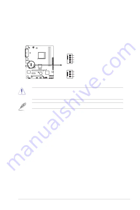
CPU and chassis fan connectors (4-pin CPU_FAN and 3-pin CHA_FAN)

Connect the fan cables to the fan connectors on the motherboard, ensuring that the 

black wire of each cable matches the ground pin of the connector.

Only the 4-pin CPU fan connector supports the ASUS Q-Fan feature.

DO NOT forget to connect the fan cables to the fan connectors. Insufficient air flow inside 

the system may damage the motherboard components. These are not jumpers! DO NOT 

place jumper caps on the fan connectors.

M4A78LT-M LX

M4A78LT-M LX fan connectors

CPU_FAN

GND
CPU FAN PWR
CPU FAN IN
CPU FAN PWM

GND
+12V
Rotation

CHA_FAN

ASUS M4A78LT-M LX

1-27

Summary of Contents for M4A78LT-M LX

Page 1: ...Motherboard M4A78LT M LX ...

Page 2: ...without intent to infringe Offer to Provide Source Code of Certain Software This product may contain copyrighted software that is licensed under the General Public License GPL and under the Lesser General Public License Version LGPL The GPL and LGPL licensed code in this product is distributed without any warranty Copies of these licenses are included in this product You may obtain the complete co...

Page 3: ... 3 Motherboard layout 1 7 1 5 4 Layout contents 1 7 1 6 Central Processing Unit CPU 1 8 1 6 1 Installing the CPU 1 8 1 6 2 Installing the heatsink and fan 1 10 1 7 System memory 1 11 1 7 1 Overview 1 11 1 7 2 Memory configurations 1 12 1 7 3 Installing a DIMM 1 16 1 7 4 Removing a DIMM 1 16 1 8 Expansion slots 1 17 1 8 1 Installing an expansion card 1 17 1 8 2 Configuring an expansion card 1 17 1 ...

Page 4: ... 5 2 2 2 Menu bar 2 5 2 2 3 Navigation keys 2 5 2 2 4 Menu items 2 6 2 2 5 Submenu items 2 6 2 2 6 Configuration fields 2 6 2 2 7 Pop up window 2 6 2 2 8 Scroll bar 2 6 2 2 9 General help 2 6 2 3 Main menu 2 7 2 3 1 System Time 2 7 2 3 2 System Date 2 7 2 3 3 SATA_1 6 2 7 2 3 4 SATA Configuration 2 8 2 3 5 System Information 2 9 2 4 Advanced menu 2 9 2 4 1 JumperFree Configuration 2 9 2 4 2 CPU Co...

Page 5: ... 16 2 5 4 APM Configuration 2 16 2 5 5 HW Monitor Configuration 2 17 2 5 6 Anti Surge Support Enabled 2 17 2 6 Boot menu 2 18 2 6 1 Boot Device Priority 2 18 2 6 2 Boot Settings Configuration 2 18 2 6 3 Security 2 19 2 7 Tools menu 2 21 2 7 1 ASUS EZ Flash 2 2 21 2 7 2 ASUS O C Profile 2 22 2 8 Exit menu 2 23 ...

Page 6: ...nt from that to which the receiver is connected Consult the dealer or an experienced radio TV technician for help The use of shielded cables for connection of the monitor to the graphics card is required to assure compliance with FCC regulations Changes or modifications to this unit not expressly approved by the party responsible for compliance could void the user s authority to operate this equip...

Page 7: ...peration safety Before installing the motherboard and adding devices on it carefully read all the manuals that came with the package Before using the product ensure that all cables are correctly connected and the power cables are not damaged If you detect any damage contact your dealer immediately To avoid short circuits keep paper clips screws and staples away from connectors slots sockets and ci...

Page 8: ...uct and software updates 1 ASUS websites The ASUS website provides updated information on ASUS hardware and software products Refer to the ASUS contact information 2 Optional documentation Your product package may include optional documentation such as warranty flyers that may have been added by your dealer These documents are not part of the standard package Typography Bold text Indicates a menu ...

Page 9: ... if you want to install 4GB or more memory on the motherboard Graphics Integrated ATI Radeon HD 3000 GPU Supports max shared memory of 1GB Supports RGB with max resolution of 2048 x 1536 85Hz Supports Microsoft DirectX 10 Supports Hybrid CrossFireX for Windows Vista or later version Refer to www amd com for the discrete GPUs that support Hybrid CrossFireX Expansion slots 1 x PCIe 2 0 x16 slot 2 x ...

Page 10: ...S 8Mb Flash ROM AMI BIOS PnP DMI2 0 WfM2 0 ACPI2 0a SM BIOS 2 5 ASUS unique features ASUS Core unlocker ASUS Q Fan ASUS CrashFree BIOS3 ASUS EZ Flash2 ASUS AI Charger ASUS MyLogo2 ASUS EPU 4 Engine ASUS Anti Surge ASUS exclusive overclocking features Intelligent overclocking tools Turbo Key SFS Stepless Frequency Selection FSB frequency tuning from 200MHz up to 550MHz at 1MHz increment Adjustable ...

Page 11: ...ost of new features and latest technologies making it another standout in the long line of ASUS quality motherboards Before you start installing the motherboard and hardware devices on it check the items in your package with the list below AMD Phenom II Athlon II Sempron 100 series CPU support This motherboard supports AMD Socket AM3 multi core processors with unique L3 cache and delivers better o...

Page 12: ... applications Hybrid CrossFireX support ATI Hybrid CrossFireX technology greatly boosts graphics performance with an onboard GPU and a discrete GPU Hybrid CrossFireX is supported by Windows Vista Windows 7 OS only Refer to www amd com for the discrete GPUs that support Hybrid CrossFireX Gigabit LAN solution The onboard LAN controller is a highly integrated Gb LAN controller It is enhanced with an ...

Page 13: ...SUS CrashFree BIOS 3 ASUS CrashFree BIOS 3 is an auto recovery tool that allows you to restore a corrupted BIOS file using the bundled support DVD or a USB flash disk that contains the BIOS file ASUS EZ Flash 2 ASUS EZ Flash 2 allows you to update the BIOS from a USB flash disk before entering the OS ASUS Q Fan ASUS Q Fan technology intelligently adjusts the CPU fan speed according to system loadi...

Page 14: ...restores the CPU parameters to their default settings ErP ready The motherboard is European Union s Energy related Products ErP ready and ErP requires products to meet certain energy efficiency requirements in regards to energy consumptions This is in line with ASUS vision of creating environment friendly and energy efficient products through product design and innovation to reduce carbon footprin...

Page 15: ...it on a grounded antistatic pad or in the bag that came with the component Before you install or remove any component switch off the ATX power supply and detach its power cord Failure to do so may cause severe damage to the motherboard peripherals or components Onboard LED The motherboard comes with a standby power LED that lights up to indicate that the system is ON in sleep mode or in soft off m...

Page 16: ...ion The edge with external ports goes to the rear part of the chassis as indicated in the image below DO NOT overtighten the screws Doing so can damage the motherboard 1 5 2 Screw holes Place six screws into the holes indicated by circles to secure the motherboard to the chassis Place this side towards the rear of the chassis Chapter 1 Product introduction 1 6 ...

Page 17: ...VGA 2 3 4 5 6 3 1 10 11 12 8 9 2 13 14 7 Connectors Jumpers Slots Page Connectors Jumpers Slots Page 1 Keyboard power 3 pin KBPWR 1 19 8 System panel connector 10 1 pin F_PANEL 1 24 2 USB device wake up 3 pin USBPW1 4 USBPW5 10 1 19 9 Speaker connector 4 pin SPEAKER 1 26 3 ATX power connectors 24 pin EATXPWR 4 pin ATX12V 1 22 10 USB connectors 10 1 pin USB56 USB78 USB910 1 25 4 CPU and chassis fan...

Page 18: ...n completely 3 Position the CPU above the socket such that the CPU corner with the gold triangle matches the socket corner with a small triangle 4 Carefully insert the CPU into the socket until it fits in place The CPU fits only in one correct orientation DO NOT force the CPU into the socket to prevent bending the pins and damaging the CPU Gold triangle Small triangle The AM3 socket has a differen...

Page 19: ...ith the heatsink package You can also refer to section 1 6 2 Installing heatsink and fan for instructions 7 Connect the CPU fan cable to the CPU_FAN connector on the motherboard DO NOT forget to connect the CPU fan connector Hardware monitoring errors can occur if you fail to plug this connector M4A78LT M LX M4A78LT M LX CPU fan connector CPU_FAN GND CPU FAN PWR CPU FAN IN CPU FAN PWM ASUS M4A78LT...

Page 20: ...therboard components If you purchased a separate CPU heatsink and fan assembly ensure that a Thermal Interface Material is properly applied to the CPU heatsink or CPU before you install the heatsink and fan assembly CPU Fan CPU Heatsink Retention bracket Retention bracket lock Retention Module Base Your boxed CPU heatsink and fan assembly should come with installation instructions for the CPU heat...

Page 21: ...he module base 5 When the fan and heatsink assembly is in place connect the CPU fan cable to the connector on the motherboard labeled CPU_FAN DO NOT forget to connect the CPU fan connector Hardware monitoring errors can occur if you fail to plug this connector 1 7 System memory 1 7 1 Overview The motherboard comes with two Double Data Rate 3 DDR3 Dual Inline Memory Modules DIMM sockets The figure ...

Page 22: ...er 78 0AGCD CDZ XMP 2048MB Kit of 2 SS N A Heat Sink Package Corsair CM3X2G1800C8D 2048MB DS N A Heat Sink Package Transcend TX1800KLU 2GK 1024MB SS N A Heat Sink Package Vendor Part No Size SS DS Brand Chip NO Timing DIMM BIOS Voltage DIMM Support A B A Data AD31600X002GMU 4096MB Kit of 2 DS N A Heat Sink Package 7 7 7 20 1 75 1 85V Corsair CM3X1G1600C9DHX 2048MB Kit of 2 SS N A Heat Sink Package...

Page 23: ... 151C E0903 A Data AD31333G002GMU 2048MB DS N A Heat Sink Package 8 8 8 24 1 65 1 85V Apacer 78 01GC6 9L0 1024MB SS Apacer AM5D5808AEWSBG0914E 9 Apacer 78 A1GC6 9L1 2048MB DS Apacer AM5D5808AEWSBG0908D 9 Corsair CM3X1024 1333C9DHX 1024MB SS N A Heat Sink Package 9 9 9 24 1 60V Corsair CM3X1024 1333C9 1024MB SS N A Heat Sink Package Corsair TR3X3G1333C9 G 3072MB Kit of 3 SS N A Heat Sink Package 9 ...

Page 24: ...ron MT8JTF12864AZ 1G4F1 1024MB SS Micron 9FF22D9KPT 9 Micron MT9JSF 12872AZ 1G4F1 1024MB SS Micron 91F22D9KPT ECC 9 Micron MT8JTF12864AY 1G4D1 3072MB Kit of 3 SS Micron 8XD22D9JNM 9 Micron MT12JSF25672AZ 1G4F1 2048MB DS Micron 91F22D9KPT ECC 9 Micron MT16JTF25664AY 1G1D1 2048MB DS Micron 8LD22 D9JNM Micron MT18JTF25664AZ 1G4F1 2048MB DS Micron 9KF27D9KPT 9 Micron MT16JTF25664AY 1G4D1 6144MB Kit of...

Page 25: ... Micron MT16JTF25664AY 1G1D1 2048MB DS Micron 8LD22D9JNL Micron MT16JTF25664AZ 1G1F1 2048MB DS Micron 9HF22D9KPT 7 Micron MT18JSF25672AZ 1G1F1 2048MB DS Micron 9GF22D9KPT ECC 7 OCZ OCZ3SOE10662GK 2048MB Kit of 2 DS N A Heat Sink Package 7 7 7 16 1 75V SAMSUNG M378B2873EH1 CF8 1024MB SS Samsung SEC 901 HCF8 K4B1G0846E SAMSUNG M378B5273BH1 CF8 4096MB DS Samsung 846 K4B2G0846B HCF8 SS Single sided DS...

Page 26: ...clips outward to unlock the DIMM 2 Remove the DIMM from the socket Support the DIMM lightly with your fingers when pressing the retaining clips The DIMM might get damaged when it flips out with extra force DIMM notch 1 1 2 1 Press the retaining clips outward to unlock a DIMM socket 2 Align a DIMM on the socket such that the notch on the DIMM matches the DIMM slot key on the socket Unlocked retaini...

Page 27: ...ou removed earlier 6 Replace the system cover When using PCI cards on shared slots ensure that the drivers support Share IRQ or that the cards do not need IRQ assignments Otherwise conflicts will arise between the two PCI groups making the system unstable and the card inoperable 1 8 3 PCI slot The PCI slot supports cards such as a LAN card SCSI card USB card and other cards that comply with PCI sp...

Page 28: ... default to pins 2 3 Keep the cap on pins 2 3 for about 5 10 seconds then move the cap back to pins 1 2 3 Plug the power cord and turn ON the computer 4 Hold down the Del key during the boot process and enter BIOS setup to reenter data If the steps above do not help remove the onboard battery and move the jumper again to clear the CMOS RTC RAM data After clearing the CMOS reinstall the battery You...

Page 29: ...ode M4A78LT M LX 2 1 2 3 5V Default 5VSB USBPW5 10 2 1 2 3 5V 5VSB Default USBPW1 4 M4A78LT M LX USB Device Wake Up 3 Keyboard power 3 pin KBPWR This jumper allows you to enable or disable the keyboard wake up feature When you set this jumper to pins 2 3 5VSB you can wake up the computer by pressing a key on the keyboard This feature requires an ATX power supply that can supply at least 1A on the ...

Page 30: ... 5 Line Out port lime This port connects to a headphone or a speaker In the 4 6 and 8 channel configurations the function of this port becomes Front Speaker Out 6 Microphone port pink This port connects to a microphone Refer to the audio configuration table below for the function of the audio ports in 2 4 6 or 8 channel configuration 4 5 3 6 8 7 2 10 9 1 11 Port Headset 2 channel 4 channel 6 chann...

Page 31: ...nnect a high definition front panel audio module to this connector set the Front Panel Select item in the BIOS to HD Audio See section 2 4 4 Onboard Device Configuration for details The front panel audio I O module is purchased separately 1 10 2 Internal connectors 1 Front panel audio connector 10 1 pin AAFP This connector is for a chassis mounted front panel audio I O module that supports either ...

Page 32: ...e power is inadequate DO NOT forget to connect the 4 pin ATX12V power plug Otherwise the system will not boot up We recommend that you use a PSU with higher power output when configuring a system with more power consuming devices or when you intend to install additional devices The system may become unstable or may not boot up if the power is inadequate If you are uncertain about the minimum power...

Page 33: ... Configuration for details The motherboard does not provide a floppy disk drive connector You could use a USB floppy disk drive when installing Windows XP operating system on a hard disk drive that includes a RAID AHCI set Due to Windows XP limitation Windows XP may not recognize the USB floppy disk drive For more details on RAID AHCI refer to the RA ID AHCI Supplementary Guide included in the fol...

Page 34: ...er LED lights up when you turn on the system power and blinks when the system is in sleep mode Hard disk drive activity LED 2 pin HDLED This 2 pin connector is for the HDD Activity LED Connect the HDD Activity LED cable to this connector The HDD Activity LED lights up or flashes when data is read from or written to the HDD Power Soft off button 2 pin PWRBTN This 2 pin connector is for the system p...

Page 35: ...2 0 specification that supports up to 480Mbps connection speed Never connect a 1394 cable to the USB connectors Doing so will damage the motherboard The USB 2 0 module is purchased separately M4A78LT M LX M4A78LT M LX USB2 0 connectors PIN 1USB 5V USB_P8 USB_P8 GND NC USB 5V USB_P7 USB_P7 GND USB78 PIN 1 USB 5V USB_P6 USB_P6 GND NC USB 5V USB_P5 USB_P5 GND USB56 PIN 1 USB 5V USB_P10 USB_P10 GND NC...

Page 36: ...nel Sounds and Audio Devices Sound Playback to configure the setting The S PDIF module is purchased separately M4A78LT M LX M4A78LT M LX Digital audio connector SPDIF_OUT 5V SPDIFOUT GND 7 Speaker connector 4 pin SPEAKER This 4 pin connector is for the chassis mounted system warning speaker The speaker allows you to hear system beeps and warnings M4A78LT M LX M4A78LT M LX Speaker Out Connector 5V ...

Page 37: ...r Only the 4 pin CPU fan connector supports the ASUS Q Fan feature DO NOT forget to connect the fan cables to the fan connectors Insufficient air flow inside the system may damage the motherboard components These are not jumpers DO NOT place jumper caps on the fan connectors M4A78LT M LX M4A78LT M LX fan connectors CPU_FAN GND CPU FAN PWR CPU FAN IN CPU FAN PWM GND 12V Rotation CHA_FAN ASUS M4A78L...

Page 38: ...t comes with the motherboard package contains the drivers software applications and utilities that you can install to avail all motherboard features The contents of the Support DVD are subject to change at any time without notice Visit the ASUS website at www asus com for updates To run the Support DVD Place the Support DVD into the optical drive The DVD automatically displays the Drivers menu if ...

Page 39: ...he support DVD into the optical drive The Drivers menu appears 2 Click the Utilities tab then click ASUS Update 3 Follow the onscreen instructions to complete the installation Quit all Windows applications before you update the BIOS using this utility Updating the BIOS To update the BIOS 1 From the Windows desktop click Start Programs ASUS ASUS Update ASUS Update to launch the ASUS Update utility ...

Page 40: ...nd then press Enter EZ Flash 2 performs the BIOS updating process and automatically reboots the system when done 2 1 2 ASUS EZ Flash 2 utility The ASUS EZ Flash 2 feature allows you to update the BIOS without using an OS based utility Before you start using this utility download the latest BIOS file from the ASUS website at www asus com This function supports USB flash disks with FAT 32 16 format ...

Page 41: ... recover the BIOS 1 Turn on the system 2 Insert the support DVD to the optical drive or the removable device that contains the BIOS file to the USB port or to the floppy disk drive if supported 3 The utility automatically checks the devices for the BIOS file When the BIOS file is found the utility reads it and starts flashing the corrupted BIOS file 4 Turn off the system after the utility complete...

Page 42: ...nly if you failed to enter BIOS Setup using the first two options Using the power button reset button or the Ctrl Alt Del keys to force reset from a running operating system can cause damage to your data or system We recommend that you always shut down the system properly from the operating system The default BIOS settings for this motherboard apply to most conditions to ensure optimum performance...

Page 43: ...ight corner of a menu screen are the navigation keys for that particular menu Use the navigation keys to select items in the menu and change the settings Menu items Select Screen Select Item Change Field Tab Select Field F1 General Help F10 Save and Exit ESC Exit v02 61 C Copyright 1985 2011 American Megatrends Inc M4A78LT M LX BIOS Setup Main Advanced Power Boot Tools Exit Use ENTER TAB or SHIFT ...

Page 44: ... display a list of options Refer to 2 2 7 Pop up window 2 2 7 Pop up window Select a menu item then press Enter to display a pop up window with the configuration options for that item 2 2 8 Scroll bar A scroll bar appears on the right side of a menu screen when there are items that do not fit on the screen Press the Up Down arrow keys or Page Up Page Down keys to display the other items on the scr...

Page 45: ...vice is installed in the system Type Auto Selects the type of SATA drive Setting this item to Auto allows automatic selection of the appropriate SATA device type Select CDROM if you are specifically configuring a CD ROM drive Select ARMD ATAPI Removable Media Device if your device is either a ZIP LS 120 or MO drive Configuration options Not Installed Auto CDROM ARMD 2 3 2 System Date Day xx xx xxx...

Page 46: ...rt Monitoring Analysis and Reporting Technology Configuration options Auto Disabled Enabled 32Bit Data Transfer Enabled Enables or disables 32 bit data transfer Configuration options Disabled Enabled 2 3 4 SATA Configuration The SATA Configuration menu allows you to configure your storage devices Select an item then press Enter to display the submenu OnChip SATA Channel Enabled Enables or disables...

Page 47: ...n Select Item Change Field Tab Select Field F1 General Help F10 Save and Exit ESC Exit Adjust System Frequency Voltage etc Advanced Settings The items and configuration options in this menu may vary depending on the AMD CPU type 2 3 5 System Information This menu gives you an overview of the general system specifications The BIOS automatically detects the items in this menu BIOS Information Displa...

Page 48: ...tio Configuration options Auto The following item only appears when you set CPU Overclocking to Manual CPU HT Reference Clock MHz 200 Sets the CPU HT Reference Clock Configuration options Min 200 Max 550 The following item only appears when you set CPU Overclocking to Overclock Profile Overclock Options Auto Selects the overclocking profile Configuration options Auto Overclock 2 Overclock 5 Overcl...

Page 49: ...he values range from 1 20000V to 1 38000V with a 0 01500V increment Use the keys to adjust the value Configuration options Auto Max 1 38000V Min 1 20000V Memory Clock Mode Auto Sets the memory clock mode Configuration options Auto Manual DRAM Timing Mode Auto Sets the DRAM timing mode Configuration options Auto DCT 0 DCT 1 Both Memory Over Voltage Auto Sets the memory over voltage The values range...

Page 50: ...uency and voltage will be reduced during the system halt state to decrease power consumption Configuration options Disabled Enabled Advanced Clock Calibration Disabled Adjusts the processor s overclocking capability When this item is set to Auto the BIOS automatically adjusts this function When this item is set to All Cores the processor has the best overclocking performance When this item is set ...

Page 51: ...ew function Configuration options Auto Disabled Enabled Frame Buffer Location Above 4G Configuration options Below 4G Above 4G This item becomes user configurable when you install an ATI graphics card into the PCIe x16 slot The 512MB option only appears when you install 1GB system memory or more The 1GB option only appears when you install 2GB system memory or more MemClk Tristate C3 ATLVID Disabl...

Page 52: ...ct HD Audio Configuration options AC97 HD Audio OnBoard LAN Controller Enabled Configuration options Disabled Enabled OnBoard LAN Boot ROM Disabled Configuration options Disabled Enabled Plug and Play O S No When this item is set to No BIOS configures all the devices in the system When this item is set to Yes and if you install a Plug and Play operating system the operating system configures the P...

Page 53: ...USB flash drives and USB hard drives Setting to Auto allows the system to detect the presence of USB devices at startup If detected the USB controller legacy mode is enabled If no USB device is detected the legacy USB support is disabled Configuration options Disabled Enabled Auto USB 2 0 Controller Mode HiSpeed Allows you to configure the USB 2 0 controller in HiSpeed 480Mbps or Full Speed 12Mbps...

Page 54: ...OS Only S3 Only Auto 2 5 2 ACPI 2 0 Support Enabled Allows you to enable or disable the Advanced Configuration and Power Interface ACPI 2 0 support Configuration options Disabled Enabled 2 5 3 ACPI APIC Support Enabled Allows you to enable or disable the Advanced Configuration and Power Interface ACPI support in the Advanced Programmable Interrupt Controller APIC When set to Enabled the ACPI APIC ...

Page 55: ...ions Disabled Enabled Power on By PS 2 Keyboard Disabled Enables or disables PS 2 Keyboard to generate a wake event Configuration options Disabled Space Bar Power Key Ctrl Esc Power on From S5 By RTC Alarm Disabled Enables or disables RTC to generate a wake event Configuration options Disabled Enabled The following item only appears when you set CPU Q Fan Function to Enabled CPU Fan Speed Low Limi...

Page 56: ...sequence from the available devices The number of device items that appears on the screen depends on the number of devices installed in the system Configuration options Removable Dev Hard Drive ATAPI CD ROM Disabled To select the boot device during system startup press F8 when ASUS logo appears To access Windows OS in Safe Mode do any of the following Press F5 when ASUS logo appears Press F8 after...

Page 57: ... RTC RAM 2 6 3 Security The Security menu items allow you to change the system security settings Select an item then press Enter to display the configuration options Change Supervisor Password Select this item to set or change the supervisor password The Supervisor Password item on top of the screen shows the default Not Installed After you set a password this item shows Installed To set a Supervi...

Page 58: ... Password Select this item to clear the user password Password Check Setup When set to Setup BIOS checks for user password when accessing the Setup utility When set to Always BIOS checks for user password both when accessing Setup and booting the system Configuration options Setup Always After you have set a supervisor password the other items appear to allow you to change other security settings ...

Page 59: ...atrends Inc Press ENTER to run the utility to select and update BIOS This utility supports 1 FAT 12 16 32 r w 2 NTFS read only 3 CD DISC read only M4A78LT M LX BIOS Setup Main Advanced Power Boot Tools Exit 2 7 1 ASUS EZ Flash 2 Allows you to run ASUS EZ Flash 2 When you press Enter a confirmation message appears Use the left right arrow key to select between Yes or No then press Enter to confirm ...

Page 60: ...file Allows you to run the utility to save and load CMOS Press Enter to run the utility This function can support devices such as a USB flash disk with FAT 32 16 format and single partition only DO NOT shut down or reset the system while updating the BIOS to prevent the system boot failure We recommend that you update the BIOS file only coming from the same memory CPU configuration and BIOS versio...

Page 61: ...ges or make other changes before saving the values to the non volatile RAM Exit Save Changes Once you are finished making your selections choose this option from the Exit menu to ensure the values you selected are saved to the CMOS RAM An onboard backup battery sustains the CMOS RAM so it stays on even when the PC is turned off When you select this option a confirmation window appears Select OK to...

Page 62: ...Fremont CA 94539 USA Telephone 1 510 739 3777 Fax 1 510 608 4555 Web site usa asus com Technical Support Telephone 1 812 282 2787 Support fax 1 812 284 0883 Online support support asus com ASUS COMPUTER GmbH Germany and Austria Address Harkort Str 21 23 D40880 Ratingen Germany Fax 49 2102 9599 11 Online contact www asus com de sales Technical Support Component Telephone 49 1805 010923 System Noteb...

Page 63: ... V1 3 1 2007 09 EN 301 357 2 V1 3 1 2006 05 EN 302 623 V1 1 1 2009 01 2006 95 EC LVD Directive EN 60950 1 2006 EN 60950 1 2006 A11 2009 EN 60065 2002 A1 2006 A11 2008 2009 125 EC ErP Directive Regulation EC No 1275 2008 EN 62301 2005 Regulation EC No 642 2009 EN 62301 2005 Regulation EC No 278 2009 EN 62301 2005 Ver 110101 CE marking Declaration Date Jan 20 2011 Year to begin affixing CE marking 2...

Reviews: