background image

6. 

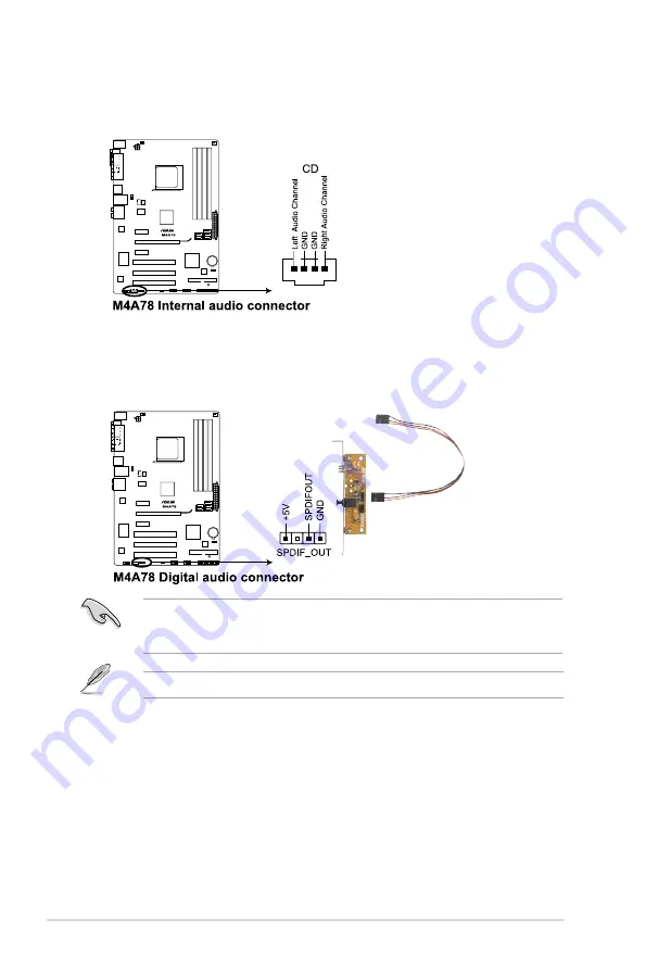
Optical drive audio in connector (4-pin CD)

This connector allows you to receive stereo audio input from sound sources such as a 

CD-ROM, TV tuner, or MPEG card.

7. 

Digital audio connector (4-1 pin SPDIF_OUT)

This connector is for an additional Sony/Philips Digital Interface (S/PDIF) ports.

Ensure that the audio device of Sound playback is 

Realtek High Definition Audio (the 

name may be different based on the OS)

. Go to 

Start > Control Panel > Sounds and 

Audio Devices > Sound Playback

 to configure the setting.

The S/PDIF module is purchased separately.

1-28

ASUS M4A78

Summary of Contents for M4A78

Page 1: ...Motherboard M4A78 ...

Page 2: ...ICULAR PURPOSE IN NO EVENT SHALL ASUS ITS DIRECTORS OFFICERS EMPLOYEES OR AGENTS BE LIABLE FOR ANY INDIRECT SPECIAL INCIDENTAL OR CONSEQUENTIAL DAMAGES INCLUDING DAMAGES FOR LOSS OF PROFITS LOSS OF BUSINESS LOSS OF USE OR DATA INTERRUPTION OF BUSINESS AND THE LIKE EVEN IF ASUS HAS BEEN ADVISED OF THE POSSIBILITY OF SUCH DAMAGES ARISING FROM ANY DEFECT OR ERROR IN THIS MANUAL OR PRODUCT SPECIFICATI...

Page 3: ...cement direction 1 6 1 5 2 Screw holes 1 6 1 5 3 Motherboard layout 1 7 1 5 4 Layout contents 1 7 1 6 Central Processing Unit CPU 1 8 1 6 1 Installing the CPU 1 8 1 6 2 Installing the heatsink and fan 1 10 1 7 System memory 1 11 1 7 1 Overview 1 11 1 7 2 Memory configurations 1 12 1 7 3 Installing a DIMM 1 17 1 7 4 Removing a DIMM 1 17 1 8 Expansion slots 1 18 1 8 1 Installing an expansion card 1 ...

Page 4: ...ty 2 3 2 2 BIOS setup program 2 4 2 2 1 BIOS menu screen 2 5 2 2 2 Menu bar 2 5 2 2 3 Navigation keys 2 6 2 2 4 Menu items 2 6 2 2 5 Submenu items 2 6 2 2 6 Configuration fields 2 6 2 2 7 General help 2 6 2 2 8 Pop up window 2 6 2 2 9 Scroll bar 2 6 2 3 Main menu 2 7 2 3 1 System Time 2 7 2 3 2 System Date 2 7 2 3 3 Primary IDE Master Slave 2 7 2 3 4 SATA 1 SATA 2 SATA 3 SATA 5 SATA 6 and ESATA 2 ...

Page 5: ... 16 2 5 2 ACPI Support 2 16 2 5 3 ACPI APIC Support 2 16 2 5 4 APM Configuration 2 16 2 5 5 HW Monitor Configuration 2 17 2 6 Boot menu 2 18 2 6 1 Boot Device Priority 2 18 2 6 2 Boot Settings Configuration 2 18 2 6 3 Security 2 19 2 7 Tools menu 2 20 2 7 1 ASUS EZ Flash 2 2 20 2 7 2 Express Gate 2 21 2 7 3 AI NET 2 2 21 2 8 Exit menu 2 22 ...

Page 6: ...na Increase the separation between the equipment and receiver Connect the equipment to an outlet on a circuit different from that to which the receiver is connected Consult the dealer or an experienced radio TV technician for help The use of shielded cables for connection of the monitor to the graphics card is required to assure compliance with FCC regulations Changes or modifications to this unit...

Page 7: ...ler Operation safety Before installing the motherboard and adding devices on it carefully read all the manuals that came with the package Before using the product ensure that all cables are correctly connected and the power cables are not damaged If you detect any damage contact your dealer immediately To avoid short circuits keep paper clips screws and staples away from connectors slots sockets a...

Page 8: ... and software products Refer to the ASUS contact information 2 Optional documentation Your product package may include optional documentation such as warranty flyers that may have been added by your dealer These documents are not part of the standard package Typography Bold text Indicates a menu or an item to select Italics Used to emphasize a word or a phrase Key Keys enclosed in the less than an...

Page 9: ... a total memory of 4GB capacity or more Windows 32 bit operating system may only recognize less than 3GB We recommend a maximum of 3GB system memory if you are using a Windows 32 bit operating system Expansion slots 1 x PCI Express x16 slot 2 x PCI Express x1 slots 3 x PCI slots Storage 1 x UltraDMA 133 100 connector 5 x Serial ATA 3Gb s connectors support RAID 0 RAID 1 and RAID 0 1 and JBOD only ...

Page 10: ...ront panel audio connector 1 x system panel connector 1 x CD audio in connector 1 x S PDIF Out connector 1x CPU Chassis Power Fan connectors 24 pin ATX power connector 4 pin ATX 12V power connector BIOS 8Mb Flash ROM AMI BIOS PnP DMI v2 0 WfM2 0 ACPI2 0a SM BIOS v2 5 Accessories 1 x Serial ATA cable 1 x UltraDMA 133 100 cable 1x I O Shield User manual Form Factor ATX form factor 12 x 8 2 30 6cm x ...

Page 11: ...nom X3 Athlon X2 Athlon Sempron Phenom II Athlon X4 Athlon X3 Athlon X2 processors with 2MB 1MB 512K L2 cache based on 64 bit architecture It features dual channel DDR2 1066 memory support and accelerates data transfer rate up to 5200MT s via HyperTransport 3 0 based system bus and AMD Cool n Quiet Technology 1 3 Special features 1 3 1 Product highlights Chapter 1 Product introduction 1 1 Welcome ...

Page 12: ... monitors system operation and automatically adjusts CPU voltage and frequency for a cool and quiet operating environment Native DDR2 1066 support This motherboard supports native DDR2 1066 It provides faster data transfer rate and more bandwidth to increase memory data transfer rate and computing efficiency enhancing system performance in 3D graphics and other memory demanding applications DDR2 1...

Page 13: ...NY PHILIPS Digital Interface jacks It allows you to transfer digital audio without converting to analog format and keeps the best signal quality Serial ATA 3Gb s technology The motherboard supports next generation SATA hard drives based on the new SATA 3Gb s storage specification The onboard SB700 southbridge allows RAID 0 RAID 1 RAID 0 1 and JBOD only for Windows Vista OS configurations for Seria...

Page 14: ...CrashFree BIOS 3 ASUS CrashFree BIOS 3 is an auto recovery tool that allows you to restore a corrupted BIOS file using the bundled support DVD or USB disk that contains the BIOS file ASUS EZ Flash 2 ASUS EZ Flash 2 is a utility that allows you to update the BIOS without using an OS based utility ASUS Q Fan ASUS Q Fan technology intelligently adjusts CPU and chassis fan speeds according to system l...

Page 15: ... with a standby power LED that lights up to indicate that the system is ON in sleep mode or in soft off mode This is a reminder that you should shut down the system and unplug the power cable before removing or plugging in any motherboard component The illustration below shows the location of the onboard LED Green ASUS This motherboard and its packaging comply with the European Union s Restriction...

Page 16: ...ntation The edge with external ports goes to the rear part of the chassis as indicated in the image below 1 5 2 Screw holes Place six screws into the holes indicated by circles to secure the motherboard to the chassis Do not overtighten the screws Doing so can damage the motherboard Place this side towards the rear of the chassis 1 6 ASUS M4A78 ...

Page 17: ...BPWR 1 20 11 System panel connector 20 8 pin F_PANEL 1 26 4 CPU Chassis Power fan connectors 4 pin CPU_FAN 3 pin CHA_FAN 3 pin PWR_FAN 1 29 12 USB connectors 10 1 pin USB78 USB910 USB1112 1 27 5 AMD CPU socket AM2 1 8 13 Digital audio connector 4 1 pin SPDIF_OUT 1 28 6 DDR2 DIMM slots 1 11 14 Optical drive audio in connector 4 pin CD 1 28 7 Serial ATA connectors 7 pin SATA1 2 3 5 6 1 25 15 Front p...

Page 18: ...he CPU socket is not compatible with AMD Opteron processors Do not install an Opteron processor on this motherboard 1 6 1 Installing the CPU To install a CPU 1 Locate the CPU socket on the motherboard 2 Press the lever sideways to unlock the socket then lift it up to a 90 100 angle Socket lever Ensure that the socket lever is lifted up to 90 100 angle otherwise the CPU will not fit in completely 1...

Page 19: ...l triangle 5 When the CPU is in place push down the socket lever to secure the CPU The lever clicks on the side tab to indicate that it is locked 6 Install a CPU heatsink and fan following the instructions that came with the heatsink package You can also refer to section 1 6 2 Installing heatsink and fan for instructions 7 Connect the CPU fan cable to the CPU_FAN connector on the motherboard Do no...

Page 20: ...ng other motherboard components If you purchased a separate CPU heatsink and fan assembly ensure that a Thermal Interface Material is properly applied to the CPU heatsink or CPU before you install the heatsink and fan assembly CPU Fan CPU Heatsink Retention bracket Retention bracket lock Retention Module Base Your boxed CPU heatsink and fan assembly should come with installation instructions for t...

Page 21: ... CPU_FAN Do not forget to connect the CPU fan connector Hardware monitoring errors can occur if you fail to plug this connector 1 7 System memory 1 7 1 Overview The motherboard comes with four Double Data Rate 2 DDR2 Dual Inline Memory Modules DIMM sockets A DDR2 module has the same physical dimensions as a DDR DIMM but has a 240 pin footprint compared to the 184 pin DDR DIMM DDR2 DIMMs are notche...

Page 22: ...aximum of 3GB system memory if you are using a 32 bit Windows OS Install a 64 bit Windows OS when you want to install 4GB or more memory on the motherboard This motherboard does not support DIMMs made up of 256 megabits Mb or less The motherboard supports up to 16GB memory modules on Windows XP Professional x64 and Vista x64 editions You may install a maximum of 4GB DIMMs on each slot M4A78 Mother...

Page 23: ...S7E0636B Apacer 1G Apacer AU01GE667C5KBGC DS 5 AM4B5708MIJS7E0627B Apacer 2G Apacer 78 A1G9O 9K4 DS 5 AM4B5808CQJS7E0749B Apacer 1G Transcend 506010 4894 DS 5 E5108AJBG 6E E Elpida 512MB ADATA M2OAD5G3H3160Q1C52 SS N A AD29608A8A 3EG20813 ADATA 1G ADATA M2OAD5G314170Q1C58 DS N A AD29608A8A 3EG80814 ADATA 2G ADATA M2OAD5H3J4170I1C53 DS N A AD20908A8A 3EG 30724 ADATA 512MB PSC AL6E8E63J 6E1 SS 5 A3R...

Page 24: ...ECC Micron 1G Micron MT9HTF12872AY 800E1 SS 6 D9HNP 7YE22 ECC Micron 1G Micron MT18HTF12872AY 80ED4 DS 5 6TD22D9GKX ECC Micron 1G Corsair XMS2 6400 DS 4 Heat Sink Package Corsair 1G Corsair XMS2 6400 DS 5 Heat Sink Package Corsair 4G Kit of 2 Corsair CM2X2048 6400C5DHX DS 5 Heat Sink Package Corsair 4G Kit of 2 Corsair CM2X2048 6400C5 DS 5 Heat Sink Package Corsair 2G Kit of 2 EPP Crucial BL12864A...

Page 25: ...ge GEIL 2G GEIL GE28GB800C5QC DS 5 Heat Sink Package GEIL 2G GEIL GE28GB800C4QC DS 4 Heat Sink Package GEIL 2G GEIL GE24GB800C4DC DS 4 Heat Sink Package GEIL 2G GEIL GE24GB800C5DC DS 5 Heat Sink Package GEIL 1G G SKILL F2 6400CL4D 2GBPK DS 4 Heat Sink Package G SKILL 1G G SKILL F2 6400CL4D 2GBHK DS 4 Heat Sink Package G SKILL 2G G SKILL F2 6400CL5D 4GBPQ DS 5 Heat Sink Package G SKILL 2G G SKILL F...

Page 26: ...ingston KHX8500D2 512 SS N A Heat Sink Package Kingston 512MB Kingston KVR1066D2N7 512 SS N A E5108AJBG 1J E Elpida 512MB Kingston KHX8500D2K2 1GN SS N A Heat Sink Package Kingston 1G Kingston KHX8500D2K2 2GN DS N A Heat Sink Package Kingston 1G Kingston KVR1066D2N7 1G DS N A E5108AJBG 1J E Elpida 1G Kingston KHX8500D2 1G DS N A Heat Sink Package Kingston 1G Qimonda HYS64T128020EU 19F C DS 6 HYB18...

Page 27: ...MM is keyed with a notch so that it fits in only one direction DO NOT force a DIMM into a socket to avoid damaging the DIMM 3 Firmly insert the DIMM into the socket until the retaining clips snap back in place and the DIMM is properly seated Locked Retaining Clip 3 1 7 4 Removing a DIMM To remove a DIMM 1 Simultaneously press the retaining clips outward to unlock the DIMM 2 Remove the DIMM from th...

Page 28: ... you removed earlier 6 Replace the system cover 1 8 2 Configuring an expansion card After installing the expansion card configure it by adjusting the software settings 1 Turn on the system and change the necessary BIOS settings if any See Chapter 2 for information on BIOS setup 2 Assign an IRQ to the card 3 Install the software drivers for the expansion card When using PCI cards on shared slots en...

Page 29: ...ord 2 Move the jumper cap from pins 1 2 default to pins 2 3 Keep the cap on pins 2 3 for about 5 10 seconds then move the cap back to pins 1 2 3 Plug the power cord and turn ON the computer 4 Hold down the Del key during the boot process and enter BIOS setup to reenter data If the steps above do not help remove the onboard battery and move the jumper again to clear the CMOS RTC RAM data After clea...

Page 30: ...can supply at least 1A on the 5VSB lead and a corresponding setting in the BIOS This jumper is for the rear USB ports 3 USB device wake up 3 pin USBPW1 6 and USBPW7 12 Set this jumper to 5V to wake up the computer from S1 sleep mode CPU stopped DRAM refreshed system running in low power mode using the connected USB devices Set to 5VSB to wake up from S3 and S4 sleep modes no power to CPU DRAM in s...

Page 31: ...bps connection BLINKING Data activity GREEN 1 Gbps connection LAN port SPEED LED ACT LINK LED 4 11 2 14 1 15 3 12 5 6 7 8 9 10 13 5 Center Subwoofer port orange This port connects the center subwoofer speakers 6 Rear Speaker Out port black This port connects the rear speakers in a 4 channel 6 channel or 8 channel audio configuration 7 Line In port light blue This port connects the tape CD DVD play...

Page 32: ...In Mic In Orange Center Subwoofer Center Subwoofer Black Rear Speaker Out Rear Speaker Out Rear Speaker Out Gray Side Speaker Out Refer to the audio configuration table below for the function of the audio ports in 2 4 6 or 8 channel configuration Ensure the audio device of sound playback is Realtek High Definition Audio the name may be different based on the OS Go to Start Control Panel Sounds and...

Page 33: ...g can provide at least 15 A on 12 V and that the PSU has a minimum power rating of 300 W The system may become unstable or may not boot up if the power is inadequate Do not forget to connect the 4 pin ATX 12 V power plug Otherwise the system will not boot up We recommend that you use a PSU with higher power output when configuring a system with more power consuming devices or when you intend to in...

Page 34: ...er setting Mode of device s Cable connector Single device Cable Select or Master Black Two devices Cable Select Master Black Slave Gray Master Master Black or gray Slave Slave Pin 20 on the IDE connector is removed to match the covered hole on the Ultra DMA cable connector This prevents incorrect insertion when you connect the IDE cable Use the 80 conductor IDE cable for Ultra DMA 133 100 IDE devi...

Page 35: ...cables for Serial ATA 3Gb s hard disk and optical disk drives The Serial ATA 3Gb s is backward compatible with Serial ATA 1 5Gb s specification The data transfer rate of the Serial ATA 3Gb s is faster than the standard parallel ATA with 133 MB s Ultra DMA133 If you install Serial ATA hard disk drives you can create a RAID 0 RAID 1 RAID 0 1 and JBOD only for Windows Vista OS configuration through t...

Page 36: ...lights up or flashes when data is read from or written to the HDD System warning speaker 4 pin SPEAKER This 4 pin connector is for the chassis mounted system warning speaker The speaker allows you to hear system beeps and warnings ATX power button soft off button 2 pin PWRSW This connector is for the system power button Pressing the power button turns the system on or puts the system in sleep or s...

Page 37: ... then install the module to a slot opening at the back of the system chassis These USB connectors comply with USB 2 0 specification that supports up to 480 Mbps connection speed Never connect a 1394 cable to the USB connectors Doing so will damage the motherboard The USB 2 0 module is purchased separately Chapter 1 Product introduction 1 27 ...

Page 38: ...onnector 4 1 pin SPDIF_OUT This connector is for an additional Sony Philips Digital Interface S PDIF ports Ensure that the audio device of Sound playback is Realtek High Definition Audio the name may be different based on the OS Go to Start Control Panel Sounds and Audio Devices Sound Playback to configure the setting The S PDIF module is purchased separately 1 28 ASUS M4A78 ...

Page 39: ...C 97 audio standard Connect one end of the front panel audio I O module cable to this connector Do not forget to connect the fan cables to the fan connectors Insufficient air flow inside the system may damage the motherboard components These are not jumpers Do not place jumper caps on the fan connectors Only the CPU fan supports the ASUS Q FAN feature 9 CPU Chassis and PowerFan connectors 4 pin CP...

Page 40: ...and corresponding updates to maximize the features of your hardware Motherboard settings and hardware options vary Use the setup procedures presented in this chapter for reference only Refer to your OS documentation for detailed information Ensure that you install Windows XP Service Pack 3 or later versions Windows Vista Service Pack 1 or later versions before installing the drivers for better com...

Page 41: ...lace the support DVD in the optical drive The Drivers menu appears 2 Click the Utilities tab then click Install ASUS Update 3 Follow the onscreen instructions to complete the installation Quit all Windows applications before you update the BIOS using this utility Updating the BIOS To update the BIOS 1 From the Windows desktop click Start Programs ASUS ASUS Update ASUS Update to launch the ASUS Upd...

Page 42: ...06 Current ROM Update ROM A Note FLASH TYPE MXIC 25L8005 PATH A BOARD M4A78 VER 0203 DATE 02 03 2009 BOARD Unknown VER Unknown DATE Unknown Enter Select or Load Tab Switch V Drive Info Up Down Home End Move B Backup ESC Exit Enter the BIOS setup program Go to the Tools menu to select EZ Flash 2 and press Enter to enable it Press Tab to switch between drives until the correct BIOS file is found 4 W...

Page 43: ...Turn on the system 2 Insert the support DVD or USB flash disk containing the BIOS file to the optical drive or USB port 3 The utility displays the following message and automatically checks the support DVD or USB flash disk for the BIOS file When found the utility reads the BIOS file and starts erasing the corrupted BIOS file Bad BIOS checksum Starting BIOS recovery Checking for USB Device USB Dev...

Page 44: ...u wish to enter Setup after POST reboot the system by doing any of the following procedures Restart using the OS standard shut down procedure Press Ctrl Alt Del simultaneously Press the reset button on the system chassis Press the power button to turn the system off then back on Using the power button reset button or the Ctrl Alt Del keys to force reset from a running operating system can cause da...

Page 45: ...chapter are for reference purposes only and may not exactly match what you see on your screen Visit the ASUS website at www asus com to download the latest BIOS information Menu items Menu bar Configuration fields General help Select Screen Select Item Change Field Tab Select Field F1 General Help F10 Save and Exit ESC Exit v02 61 C Copyright 1985 2008 American Megatrends Inc BIOS SETUP UTILITY Ma...

Page 46: ... menu screen are the navigation keys for that particular menu Use the navigation keys to select items in the menu and change the settings Some of the navigation keys differ from one screen to another 2 2 7 General help At the top right corner of the menu screen is a brief description of the selected item 2 2 8 Pop up window Select a menu item then press Enter to display a pop up window with the co...

Page 47: ...vable Media Device if your device is either a ZIP LS 120 or MO drive Configuration options Not Installed Auto CDROM ARMD LBA Large Mode Auto Enables or disables the LBA mode Setting to Auto enables the LBA mode if the device supports this mode and if the device was not previously formatted with LBA mode disabled Configuration options Disabled Auto Refer to section 2 2 1 BIOS menu screen for inform...

Page 48: ...omatically detects the values opposite the dimmed items Device Vendor Size LBA Mode Block Mode PIO Mode Async DMA Ultra DMA and SMART monitoring These values are not user configurable These items show Not Detected if no Serial ATA device is installed in the system LBA Large Mode Auto Enables or disables the LBA mode Setting to Auto enables the LBA mode if the device supports this mode and if the d...

Page 49: ...ly detects the items in this menu BIOS Information Displays the auto detected BIOS information Processor Displays the auto detected CPU specification System Memory Displays the auto detected system memory 2 4 Advanced menu The Advanced menu items allow you to change the settings for the CPU and other system devices Be cautious when changing the settings of the Advanced menu items Incorrect field v...

Page 50: ...locking Auto Allows you to select the PCIE Overclocking Configuration options Auto Manual The following item appears only when the PCIE Overclocking item is set to Manual PCIE Clock 100 Allows you to set the PCIE clock The valid value is between 100 and 150 Processor Frequency Multiplier Auto Allows you to select the processor frequency Configuration options Auto x4 0 800 MHz x5 0 1000 MHz x6 0 12...

Page 51: ... CLK 12 CLK 13 CLK 14 CLK 15 CLK 16 CLK 17 CLK 18 CLK 19 CLK 20 CLK 21 CLK 22CLK 23 CLK 24 CLK 25 CLK 26 CLK Auto tWR Auto Allows you to specify when the last write is registered by the DRAM Configuration options Auto 3 CLK 4 CLK 5 CLK 6 CLK TRRD Auto Allows you to set TRRD Configuration options 2 CLK 3 CLK 4 CLK 5 CLK Auto tRWTTO Auto Allows you to set tRWTTO Configuration options Auto 2 CLK 3 CL...

Page 52: ...ormation that the BIOS automatically detects GART Error Reporting Disabled This option should remain disabled for the normal operation The driver developer may enable it for testing purpose Configuration options Disabled Enabled Microcode Updation Enabled Allows you to enable or disable the microcode updation Configuration options Disabled Enabled Secure Virtual Machine Mode Enabled Allows you to ...

Page 53: ...le Remapping Enabled Enables or disables the memory remapping around memory hole Configuration options Disabled Enabled DCT Unganged Mode Auto Allows you to enable or disable unganged DRAM mode Configuration options Auto Always Power Down Enable Enabled Enables or disables the DDR power down mode Configuration options Disabled Enabled ECC Configuration ECC Mode Disabled Enables or disables the DRA...

Page 54: ...g SPDIF Output Allows you to select SPDIF_OUT mode Configuration options HDMI Output SPDIF Output Onboard LAN Controller Enabled Allows you to enable or disable the Onboard LAN Configuration options Enabled Disabled Onboard LAN Boot ROM Disabled Allows you to enable or disable the Onboard LAN Boot ROM Configuration options Enabled Disabled 2 4 5 PCI PnP The PCI PnP menu items allow you to change t...

Page 55: ...f no USB device is detected the legacy USB support is disabled Configuration options Disabled Enabled Auto USB 2 0 Controller Mode HiSpeed Allows you to configure the USB 2 0 controller in HiSpeed 480 Mbps or Full Speed 12 Mbps Configuration options FullSpeed HiSpeed 2 4 6 USB Configuration The items in this menu allows you to change the USB related features Select an item then press Enter to disp...

Page 56: ...to enter the ACPI S3 Suspend to RAM sleep state default In S3 sleep state the system appears to be off and consumes less power than in the S1 state When signaled by a wake up device or event the system resumes to its working state exactly where it was left off Auto Detected by OS 2 5 2 ACPI Support Disabled Allows you to add more tables for Advanced Configuration and Power Interface ACPI 2 0 speci...

Page 57: ...or automatically detects and displays the motherboard and CPU temperatures Select Ignored if you do not wish to display the detected temperatures CPU Chassis Power Fan Speed xxxxRPM or Ignored The onboard hardware monitor automatically detects and displays the CPU chassis and power fan speed in rotations per minute RPM If the fan is not connected to the motherboard the field shows N A Select Ignor...

Page 58: ...cify the boot device priority sequence from the available devices The number of device items that appears on the screen depends on the number of devices installed in the system Configuration options Removable Dev Hard Drive ATAPI CD ROM Disabled Set this item to Enabled to use the ASUS MyLogo 2 feature AddOn ROM Display Mode Force BIOS Sets the display mode for option ROM Configuration options For...

Page 59: ...talled appears Bootup Num Lock On Allows you to select the power on state for the NumLock Configuration options Off On Wait for F1 If Error Enabled When set to Enabled the system waits for the F1 key to be pressed when error occurs Configuration options Disabled Enabled Hit DEL Message Display Enabled When set to Enabled the system displays the message Press DEL to run Setup during POST Configurat...

Page 60: ...this item to set or change the user password The User Password item on top of the screen shows the default Not Installed After you set a password this item shows Installed To set a User Password 1 Select the Change User Password item and press Enter 2 On the password box that appears type a password composed of at most six letters and or numbers then press Enter 3 Confirm the password when prompte...

Page 61: ...seconds Reset User Data No Allows you to clear Express Gate s user data Configuration options No Reset When setting this item to Reset make sure to save the setting to the BIOS so that the user data will be cleared the next time you enter the Express Gate User data includes the Express Gate s settings as well as any personal information stored by the web browser bookmarks cookies browsing history ...

Page 62: ... exit If you attempt to exit the Setup program without saving your changes the program prompts you with a message asking if you want to save your changes before exiting Press Enter to save the changes while exiting Exit Discard Changes Select this option only if you do not want to save the changes that you made to the Setup program If you made changes to fields other than System Date System Time a...

Reviews: