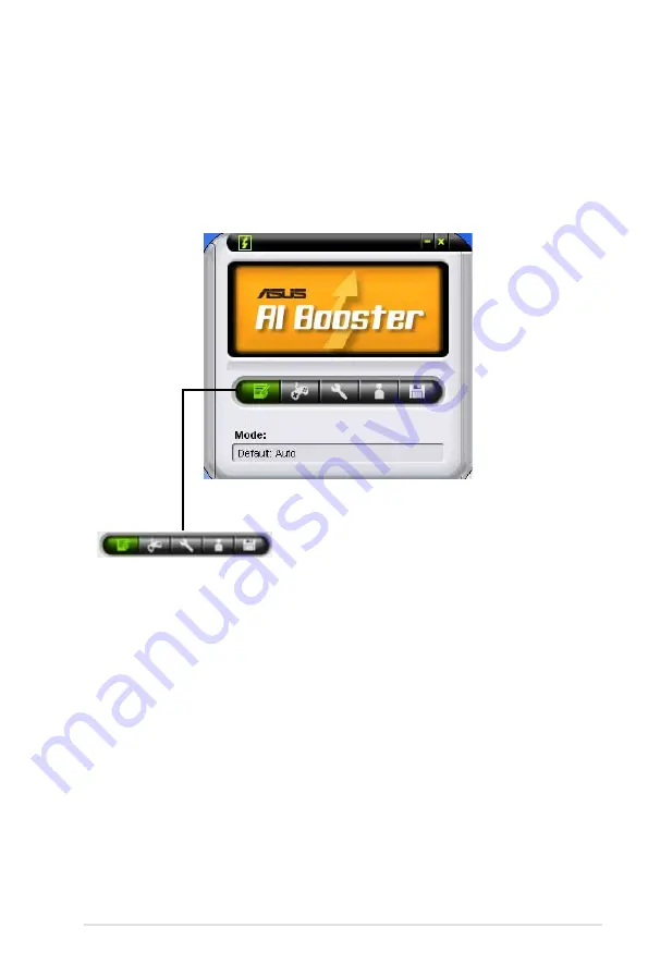
background image

ASUS M3A78-T

5-33

5.3.9 

ASUS AI Booster

The ASUS AI Booster application allows you to overclock the CPU speed in 

WIndows

®

 environment without the hassle of booting the BIOS.

After installing AI Suite from the bundled support DVD, you can launch the utility 

by double-clicking the AI Suite icon on the Windows

®

 OS taskbar and click the AI 

Booster button on the AI Suite main window. 

The options on the taskbar allow you to use the default settings, adjust CPU/

Memory/PCI-E frequency manually, or create and apply your personal overclocking 

configurations.

Summary of Contents for M3A78-T - Motherboard - ATX

Page 1: ...Motherboard M3A78 T ...

Page 2: ...CHANTABILITY OR FITNESS FOR A PARTICULAR PURPOSE IN NO EVENT SHALL ASUS ITS DIRECTORS OFFICERS EMPLOYEES OR AGENTS BE LIABLE FOR ANY INDIRECT SPECIAL INCIDENTAL OR CONSEQUENTIAL DAMAGES INCLUDING DAMAGES FOR LOSS OF PROFITS LOSS OF BUSINESS LOSS OF USE OR DATA INTERRUPTION OF BUSINESS AND THE LIKE EVEN IF ASUS HAS BEEN ADVISED OF THE POSSIBILITY OF SUCH DAMAGES ARISING FROM ANY DEFECT OR ERROR IN ...

Page 3: ...you proceed 2 1 2 2 Motherboard overview 2 2 2 2 1 Placement direction 2 2 2 2 2 Screw holes 2 2 2 2 3 Motherboard layout 2 3 2 2 4 Layout contents 2 4 2 3 Central Processing Unit CPU 2 6 2 3 1 Installing the CPU 2 6 2 3 2 Installing the heatsink and fan 2 8 2 4 System memory 2 11 2 4 1 Overview 2 11 2 4 2 Memory configurations 2 12 2 4 3 Installing a DIMM 2 13 2 4 4 Removing a DIMM 2 13 2 5 Expan...

Page 4: ... updating your BIOS 4 1 4 1 1 Creating a bootable floppy disk 4 2 4 1 2 ASUS EZ Flash 2 utility 4 3 4 1 3 AFUDOS utility 4 4 4 1 4 ASUS Update utility 4 6 4 2 BIOS setup program 4 9 4 2 1 BIOS menu screen 4 10 4 2 2 Menu bar 4 10 4 4 3 Navigation keys 4 10 4 2 4 Menu items 4 11 4 2 5 Sub menu items 4 11 4 2 6 Configuration fields 4 11 4 2 7 Pop up window 4 11 4 2 8 Scroll bar 4 11 4 2 9 General he...

Page 5: ...bled 4 31 4 5 4 ACPI APIC Support Enabled 4 31 4 5 5 APM Configuration 4 32 4 5 6 Hardware Monitor 4 34 4 6 Boot menu 4 35 4 6 1 Boot Device Priority 4 35 4 6 2 Boot Settings Configuration 4 36 4 6 3 Security 4 37 4 7 Tools menu 4 39 4 7 1 ASUS EZ Flash 2 4 39 4 7 2 Express Gate 4 40 4 7 3 ASUS O C Profile 4 41 4 8 Exit menu 4 42 Chapter 5 Software support 5 1 Installing an operating system 5 1 5 ...

Page 6: ...AMD OverDrive AOD 5 43 5 4 RAID configurations 5 44 5 4 1 RAID definitions 5 44 5 4 2 Installing Serial ATA hard disks 5 45 5 4 3 AMD RAID configurations 5 45 5 5 Creating a RAID driver disk 5 51 5 5 1 Creating a RAID driver disk without entering the OS 5 51 5 5 2 Creating a RAID SATA driver disk in Windows 5 51 Chapter 6 ATI Hybrid CrossFireX technology support 6 1 ATI Hybrid CrossFireX 6 1 6 1 1...

Page 7: ...ause harmful interference to radio or television reception which can be determined by turning the equipment off and on the user is encouraged to try to correct the interference by one or more of the following measures Reorient or relocate the receiving antenna Increase the separation between the equipment and receiver Connect the equipment to an outlet on a circuit different from that to which the...

Page 8: ... the power supply is broken do not try to fix it by yourself Contact a qualified service technician or your retailer Operation safety Before installing the motherboard and adding devices on it carefully read all the manuals that came with the package Before using the product make sure all cables are correctly connected and the power cables are not damaged If you detect any damage contact your deal...

Page 9: ... how to change system settings through the BIOS Setup menus Detailed descriptions of the BIOS parameters are also provided Chapter 5 Software support This chapter describes the contents of the support DVD that comes with the motherboard package and the software Chapter 6 ATI Hybrid CrossFireX support This chapter describes the ATI Hybrid CrossFireX feature and shows the graphics card installation ...

Page 10: ... Key1 Key2 Key3 If you must press two or more keys simultaneously the key names are linked with a plus sign Example Ctrl Alt D Command Means that you must type the command exactly as shown then supply the required item or value enclosed in brackets Example At the DOS prompt type the command line afudos M3A78T rom DANGER WARNING Information to prevent injury to yourself when trying to complete a ta...

Page 11: ...than 3GB Hence a total installed memory of less than 3GB is recommended VGA Integrated ATI Radeon HD 3300 GPU SidePort Memory onboard 128MB DDR3 1333 memory Supports HDMI Technology HDCP compliant with max resolution up to 1920 x 1200 1080P Supports DVI with max resolution up to 2560 x 1600 60Hz Supports D Sub with max resolution up to 2560 x 1440 75 Hz Hybrid CrossFireX support For Windows Vista ...

Page 12: ...SUS Noise Filter ASUS EZ DIY ASUS Q Shield ASUS Q Connector ASUS O C Profile ASUS EZ Flash 2 Other features Uses 100 All High quality Conductive Polymer Capacitors ASUS MyLogo 2 ASUS exclusive overclocking features Intelligent overclocking tools AI Overclocking intelligent CPU frequency tuner ASUS AI Booster utility Precision Tweaker 2 vCore Adjustable CPU voltage at 0 0125V increment vDIMM 35 ste...

Page 13: ...onnector 2 x Chassis Fan connectors 1 x Power Fan connector 1 x IEEE1394a connector 1 x Front panel audio connector 1 x S PDIF Out Header 1 x Chassis Intrusion connector 1 x CD audio in 1 x 24 pin ATX Power connector 1 x 4 pin ATX 12V Power connector 1 x System Panel Q Connector BIOS features 8 Mb Flash ROM AMI BIOS PnP DMI 2 0 WfM2 0 SM BIOS 2 5 ACPI 2 0a ASUS EZ Flash 2 Support DVD contents Driv...

Page 14: ...xiv ...

Page 15: ...1 Chapter 1 Product introduction This chapter describes the motherboard features and the new technologies it supports ...

Page 16: ...ASUS M3A78 T Chapter summary 1 1 1 Welcome 1 1 1 2 Package contents 1 1 1 3 Special features 1 2 ...

Page 17: ...check the items in your package with the list below If any of the above items is damaged or missing contact your retailer 1 2 Package contents Check your motherboard package for the following items Motherboard ASUS M3A78 T Cables Serial ATA power cables Serial ATA signal cables Ultra DMA 133 100 66 cable Floppy disk drive cable Accessories 1 x ASUS Q Shield 1 x ASUS Q Connector Kit USB 1394 system...

Page 18: ...ides 2 6 times more bandwidth than HyperTransport 1 0 radically improving system efficiency to create a smoother faster computing environment AMD Socket AM2 Athlon Series Sempron CPU support This motherboard supports AMD Socket AM2 Athlon Series Sempron processors It features 2000 1600 MT s HyperTransport based system bus dual channel un buffered DDR2 800 memory support and AMD Cool n Quiet Techno...

Page 19: ...onitors SidePort Memory This motherboard features SidePort Memory an individual onboard DDR3 memory serving as memory buffer for integrated graphics With low CPU usage the SidePort Memory provides integrated graphics acceleration and effectively boosts graphics performance PCIe 2 0 support This motherboard supports the latest PCIe 2 0 devices for double speed and bandwidth which enhances system pe...

Page 20: ...o boot up ASUS Express Gate allows you to instantly surf the Internet without entering Windows You can now enjoy Skype IM YouTube webmail and Internet file downloads and sharing whenever and wherever you want The bootup speed depends on system configurations Due to chipset limitation ASUS Express Gate supports USB devices or SATA HDDs IDE mode connected to SATA port 1 4 only Set the SATA Operation...

Page 21: ...s like computer fans air conditioners and other background noises then eliminates it in the incoming audio stream while recording ASUS EZ DIY ASUS EZ DIY feature collection provides you easy ways to install computer components update the BIOS or back up your favorite settings ASUS Q Shield The specially designed ASUS Q Shield does without the usual fingers making it convenient and easy to install ...

Page 22: ... Allows the user to adjust the CPU voltage in 0 125v steps and NB DRAM voltage in 0 02v steps sto finetune voltages to achieve the most precise setting for the ultimate overclocking configuration AI Booster The ASUS AI Booster allows you to overclock the CPU speed in Windows environment without the hassle of booting the BIOS C P R CPU Parameter Recall The C P R feature of the motherboard BIOS allo...

Page 23: ...ter 2 Hardware information This chapter lists the hardware setup procedures that you have to perform when installing system components It includes description of the jumpers and connectors on the motherboard ...

Page 24: ...US M3A78 T Chapter summary 2 2 1 Before you proceed 2 1 2 2 Motherboard overview 2 2 2 3 Central Processing Unit CPU 2 6 2 4 System memory 2 11 2 5 Expansion slots 2 14 2 6 Jumper 2 18 2 7 Connectors 2 19 ...

Page 25: ...erboard settings Unplug the power cord from the wall socket before touching any component Use a grounded wrist strap or touch a safely grounded object or to a metal object such as the power supply case before handling components to avoid damaging them due to static electricity Hold components by the edges to avoid touching the ICs on them Whenever you uninstall any component place it on a grounded...

Page 26: ...rientation The edge with external ports goes to the rear part of the chassis as indicated in the image below 2 2 2 Screw holes Place nine 9 screws into the holes indicated by circles to secure the motherboard to the chassis Place this side towards the rear of the chassis Make sure to unplug the power cord before installing or removing the motherboard Failure to do so can cause you physical injury ...

Page 27: ...ASUS M3A78 T 2 3 2 2 3 Motherboard layout Refer to 2 7 Connectors for more information about rear panel connectors and internal connectors ...

Page 28: ... 2 keyboard mouse combo port 2 19 2 Video Graphics Adapter VGA port 2 19 3 USB 2 0 ports 1 and 2 2 19 4 LAN RJ 45 port 2 19 5 Center Subwoofer port orange 2 19 6 Rear Speaker Out port black 2 19 7 Line In port light blue 2 19 8 Line Out port lime 2 19 9 Microphone port pink 2 19 10 Side Speaker Out port gray 2 19 11 USB 2 0 ports 3 and 4 2 20 12 External SATA port 2 20 13 IEEE 1394a port 2 20 14 D...

Page 29: ...tor 10 1 pin IE1394_2 2 27 6 CPU chassis and power fan connectors 4 pin CPU_FAN 3 pin CHA_FAN1 2 3 pin PWR_FAN 2 28 7 Chassis intrusion connector 4 1 pin CHASSIS 2 29 8 ATX power connectors 24 pin EATXPWR 4 pin ATX12V 2 30 9 Front panel audio connector 10 1 pin AAFP 2 31 10 Optical drive audio connector 4 pin CD 2 32 11 Digital audio connector 4 1 pin SPDIF_OUT 2 32 12 System panel connector 20 8 ...

Page 30: ...FX Phenom Athlon Sempron processors or for Socket AM2 Athlon series Sempron processors Socket lever The AM2 AM2 socket has a different pinout from the 940 pin socket designed for the AMD Opteron processor Make sure you use a CPU designed for the AM2 AM2 socket The CPU fits in only one correct orientation DO NOT force the CPU into the socket to prevent bending the connectors on the socket and damag...

Page 31: ...all triangle 4 Carefully insert the CPU into the socket until it fits in place 5 When the CPU is in place push down the socket lever to secure the CPU The lever clicks on the side tab to indicate that it is locked 6 Install a CPU heatsink and fan following the instructions that came with the heatsink package Gold triangle Small triangle ...

Page 32: ...e CPU heatsink and the retention mechanism If the instructions in this section do not match the CPU documentation follow the latter Retention module base CPU heatsink CPU fan Retention bracket lock Retention bracket Make sure that you use only AMD certified heatsink and fan assembly The retention module base is already installed on the motherboard upon purchase You do not have to remove the retent...

Page 33: ...ock to the retention module base A clicking sound denotes that the retention bracket is in place 4 Push down the retention bracket lock on the retention mechanism to secure the heatsink and fan to the module base Make sure that the fan and heatsink assembly perfectly fits the retention mechanism module base otherwise you cannot snap the retention bracket in place ...

Page 34: ...ly is in place connect the CPU fan cable to the connector on the motherboard labeled CPU_FAN Do not forget to connect the CPU fan connector Hardware monitoring errors can occur if you fail to plug this connector This connector is backward compatible with old 3 pin CPU fan ...

Page 35: ... Overview The motherboard comes with four Double Data Rate 2 DDR2 Dual Inline Memory Modules DIMM sockets The figure illustrates the location of the DDR2 DIMM sockets Channel Sockets Channel A DIMM_A1 and DIMM_A2 Channel B DIMM_B1 and DIMM_B2 ...

Page 36: ...ded that you obtain memory modules from the same vendor When installing a total memory of 4GB capacity or more Windows 32 bit operation system may only recognize less than 3GB Hence a total installed memory of less than 3GB is recommended This motherboard does not support memory modules made up of 128 Mb chips Mode Sockets DIMM_A1 yellow DIMM_A2 black DIMM_B1 yellow DIMM_B2 black Single Channel Po...

Page 37: ...the DIMM 2 Remove the DIMM from the socket A DDR2 DIMM is keyed with a notch so that it fits in only one direction Do not force a DIMM into a socket to avoid damaging the DIMM The DDR2 DIMM sockets do not support DDR DIMMs DO not install DDR DIMMs to the DDR2 DIMM sockets Unplug the power supply before adding or removing DIMMs or other system components Failure to do so can cause severe damage to ...

Page 38: ... seated on the slot 5 Secure the card to the chassis with the screw you removed earlier 6 Replace the system cover 2 5 2 Configuring an expansion card After installing the expansion card configure the it by adjusting the software settings 1 Turn on the system and change the necessary BIOS settings if any See Chapter 4 for information on BIOS setup 2 Assign an IRQ to the card Refer to the tables on...

Page 39: ...lder for PCI Steering 11 6 IRQ Holder for PCI Steering 12 7 Reserved 13 8 Numeric Data Processor 14 9 Primary IDE Channel 15 10 Secondary IDE Channel These IRQs are usually available for ISA or PCI devices IRQ assignments for this motherboard A B C D E F G H PCIE x16_1 shared shared shared shared PCIE x16_2 shared shared shared shared PCIE x16_3 shared shared shared shared USB 1 0 controller 1 sha...

Page 40: ...lot 2 5 6 PCI Express 2 0 x16 slot blue This motherboard supports PCI Express 2 0 x16 graphics cards that complies with the PCI Express specifications Refer to the figure below for the location of the slot 2 5 7 Universal PCI Express x16 slots black and white This motherboard also supports two universal PCI Express 2 0 x16 slot at maximum x8 white and x4 black mode The operating frequency of the s...

Page 41: ...s Hybird CrossFireX mode Currently only AMD HD3470 HD3450 HD2400XT and HD2400Pro graphics cards support the Hybrid CrossFireX function If you install two VGA cards we recommend that you plug the rear chassis fan cable to the motherboard connector labeled CHA_FAN1 or CHA_FAN2 for better thermal environment See page 2 28 for the connector location Visit the AMD official website at www amd com for mo...

Page 42: ...4 Hold down the Del key during the boot process and enter BIOS setup to re enter data Except when clearing the RTC RAM never remove the cap on CLRTC jumper default position Removing the cap will cause system boot failure If the steps above do not help remove the onboard battery and move the jumper again to clear the CMOS RTC RAM data After the CMOS clearance reinstall the battery You do not need t...

Page 43: ...ts the center subwoofer speakers 6 Rear Speaker Out port black This port connects the rear speakers in a 4 channel 6 channel or 8 channel audio configuration 7 Line In port light blue This port connects the tape CD DVD player or other audio sources 8 Line Out port lime This port connects a headphone or a speaker In 4 channel 6 channel and 8 channel configuration the function of this port becomes F...

Page 44: ... away and enables improved hot swap function To use hot plug set the SATA Mode Select in the BIOS settings to AHCI Mode See section 4 3 6 Storage Configuration for details 13 IEEE 1394a port This 6 pin IEEE 1394a port provides high speed connectivity for audio video devices storage peripherals PCs or portable devices 14 DVI D Out port This port is for any DVI D compatible device and is HDCP compli...

Page 45: ...ing is a configuration example for your reference Using the CPU Memory of higher speed and bandwidth with the higher version DVD player and drivers will upgrade the playback quality CPU AMD Athlon64 ADH3200IAA4DE 512KB single core DIMM Kingston DDR2 800 1G x1 BIOS share memory 256MB HDD Seagate ST3160023A ATA100 ODD Sony BWU100A To play HD DVD or Blu Ray Disc make sure to use an HDCP compliant mon...

Page 46: ...rom the Graphics Settings tree expand DTV HDMI 1 4 Click Scaling Options 5 Move the Underscan Overscan slider to adjust the overall size of the display on the HDMI DTV Using this slider increases or decreases any black borders that may be visible around the outside of the display The Scaling Options function of the DTV HDMI 1 item in the ATI CATALYST Control Center is adjustable only when you are ...

Page 47: ... is for the provided floppy disk drive FDD signal cable Insert one end of the cable to this connector then connect the other end to the signal connector at the back of the floppy disk drive Pin 5 on the connector is removed to prevent incorrect cable connection when using a FDD cable with a covered Pin 5 ...

Page 48: ...onfigure your device Pin 20 on the IDE connector is removed to match the covered hole on the Ultra DMA cable connector This prevents incorrect insertion when you connect the IDE cable Use the 80 conductor IDE cable for Ultra DMA 133 100 66 33 IDE devices If any device jumper is set as Cable Select make sure all other device jumpers have the same setting Drive jumper setting Mode of device s Cable ...

Page 49: ... of SATA signal cable to SATA device Or you may connect the right angle side of SATA cable to the onboard SATA port to avoid mechanical conflict with huge graphics cards right angle side Important note on Serial ATA Install the Windows XP Service Pack 1 before using Serial ATA For detailed instructions on how to configure RAID 0 RAID 1 RAID 5 and RAID 10 refer to the RAID manual in the support DVD...

Page 50: ...ing at the back of the system chassis These USB connectors comply with USB 2 0 specification that supports up to 480 Mbps connection speed Never connect a 1394 cable to the USB connectors Doing so will damage the motherboard You can connect the front panel USB cable to the ASUS Q Connector USB blue first and then install the Q Connector USB to the USB connector onboard if your chassis supports fro...

Page 51: ...o a slot opening at the back of the system chassis Never connect a USB cable to the IEEE 1394a connector Doing so will damage the motherboard The IEEE 1394a module is purchased separately You can connect the front panel 1394 cable to the ASUS Q Connector 1394 red first and then install the Q Connector 1394 to the 1394 connector onboard if your chassis supports front panel 1394 ports ...

Page 52: ...of each cable matches the ground pin of the connector Do not forget to connect the fan cables to the fan connectors Insufficient air flow inside the system may damage the motherboard components These are not jumpers Do not place jumper caps on the fan connectors Only the CPU_FAN CHA_FAN1 and CHA_FAN2 connectors support the ASUS Q Fan 2 feature If you install two graphics cards we recommend that yo...

Page 53: ...switch cable to this connector The chassis intrusion sensor or switch sends a high level signal to this connector when a chassis component is removed or replaced The signal is then generated as a chassis intrusion event By default the pin labeled Chassis Signal and Ground are shorted with a jumper cap Remove the jumper caps only when you intend to use the chassis intrusion detection feature ...

Page 54: ...upply requirement for your system refer to the Recommended Power Supply Wattage Calculator at http support asus com PowerSupplyCalculator PSCalculator aspx SLanguage en us for details The ATX 12 V Specification 2 0 compliant 500W PSU has been tested to support the motherboard power requirements with the following configuration CPU AMD FX 62 Memory 1024 MB DDR2 800 x4 Graphics card PCI Express x16 ...

Page 55: ...s connector We recommend that you connect a high definition front panel audio module to this connector to avail of the motherboard s high definition audio capability If you want to connect a high definition front panel audio module to this connector set the Front Panel Support Type item in the BIOS setup to HD Audio if you want to connect an AC 97 front panel audio module to this connector set the...

Page 56: ...d sources such as a CD ROM TV tuner or MPEG card 11 Digital audio connector 4 1 pin SPDIF_OUT This connector is for an additional Sony Philips Digital Interface S PDIF port s Connect the S PDIF Out module cable to this connector then install the module to a slot opening at the back of the system chassis The S PDIF module is purchased separately ...

Page 57: ...peaker 4 pin SPEAKER This 4 pin connector is for the chassis mounted system warning speaker The speaker allows you to hear system beeps and warnings ATX power button soft off button 2 pin PWRSR This connector is for the system power button Pressing the power button turns the system on or puts the system in sleep or soft off mode depending on the BIOS settings Pressing the power switch for more tha...

Page 58: ...2 34 Chapter 2 Hardware information ...

Page 59: ...3 Chapter 3 Powering up This chapter describes the power up sequence the vocal POST messages and ways of shutting down the system ...

Page 60: ...ASUS M3A78 T Chapter summary 3 3 1 Starting up for the first time 3 1 3 2 Turning off the computer 3 2 ...

Page 61: ...with green standards or if it has a power standby feature the monitor LED may light up or switch between orange and green after the system LED turns on The system then runs the power on self tests or POST While the tests are running the BIOS beeps or additional messages appear on the screen If you do not see anything within 30 seconds from the time you turned on the power the system may have faile...

Page 62: ...dows shuts down If you are using Windows Vista 1 Click the Start button then select ShutDown 2 The power supply should turn off after Windows shuts down 3 2 2 Using the dual function power switch While the system is ON pressing the power switch for less than four seconds puts the system to sleep mode or to soft off mode depending on the BIOS setting Pressing the power switch for more than four sec...

Page 63: ...4 Chapter 4 BIOS setup This chapter tells how to change the system settings through the BIOS Setup menus Detailed descriptions of the BIOS parameters are also provided ...

Page 64: ...summary 4 ASUS M3A78 T 4 1 Managing and updating your BIOS 4 1 4 2 BIOS setup program 4 9 4 3 Main menu 4 12 4 4 Advanced menu 4 17 4 5 Power menu 4 31 4 6 Boot menu 4 35 4 7 Tools menu 4 39 4 8 Exit menu 4 42 ...

Page 65: ... motherboard support DVD during POST 2 ASUS AFUDOS Updates the BIOS in DOS mode using a bootable floppy disk 3 ASUS Update Updates the BIOS in Windows environment Refer to the corresponding sections for details on these utilities Save a copy of the original motherboard BIOS file to a bootable floppy disk in case you need to restore the BIOS in the future Copy the original motherboard BIOS using th...

Page 66: ...py Drive icon d Click File from the menu then select Format A Format 3 1 2 Floppy Disk window appears e Windows XP users Select Create an MS DOS startup disk from the format options field then click Start Windows Vista environment a Insert a formatted high density 1 44 MB floppy disk to the floppy disk drive b Click from the Windows desktop then select Computer c Right click Floppy Disk Drive then...

Page 67: ...e to the floppy disk drive or the USB port Press Alt F2 during POST to display the following 2 Enter BIOS setup program Go to the Tools menu to select EZ Flash 2 and press Enter to enable it You can switch between drives by pressing Tab before the correct file is found Then press Enter 4 When the correct BIOS file is found EZ Flash 2 performs the BIOS update process and automatically reboots the s...

Page 68: ... then at the prompt type afudos o filename where the filename is any user assigned filename not more than eight alphanumeric characters for the main filename and three alphanumeric characters for the extension name A afudos oOLDBIOS1 rom Make sure that the floppy disk is not write protected and has at least 1024KB free space to save the file The succeeding BIOS screens are for reference only The a...

Page 69: ...restart your computer A 2 Copy the AFUDOS utility afudos exe from the motherboard support DVD to the bootable floppy disk you created earlier 3 Boot the system in DOS mode then at the prompt type afudos i filename where filename is the latest or the original BIOS file on the bootable floppy disk A afudos iM3A78T ROM Write the BIOS filename on a piece of paper You need to type the exact BIOS filena...

Page 70: ...manage save and update the motherboard BIOS in Windows environment The ASUS Update utility allows you to Save the current BIOS file Download the latest BIOS file from the Internet Update the BIOS from an updated BIOS file Update the BIOS directly from the Internet and View the BIOS version information This utility is available in the support DVD that comes with the motherboard package ASUS Update ...

Page 71: ... Updating the BIOS through the Internet To update the BIOS through the Internet 1 Launch the ASUS Update utility from the Windows desktop by clicking Start Programs ASUS ASUSUpdate ASUSUpdate The ASUS Update main window appears 2 Select Update BIOS from the Internet option from the drop down menu then click Next ...

Page 72: ...from a file option from the drop down menu then click Next 3 Locate the BIOS file from the Open window then click Open 4 Follow the screen instructions to complete the update process 4 From the FTP site select the BIOS version that you wish to download Click Next 5 Follow the screen instructions to complete the update process The ASUS Update utility is capable of updating itself through the Intern...

Page 73: ...ss Del during the Power On Self Test POST to enter the Setup utility otherwise POST continues with its test routines If you wish to enter Setup after POST restart the system by pressing Ctrl Alt Delete or by pressing the reset button on the system chassis You can also restart by turning the system off and then back on Do this last option only if the first two failed The Setup program is designed t...

Page 74: ... or left arrow key on the keyboard until the desired item is highlighted 4 4 3 Navigation keys At the bottom right corner of a menu screen are the navigation keys for that particular menu Use the navigation keys to select items in the menu and change the settings v04 61 C Copyright 1985 2008 American Megatrends Inc Select Screen Select Item Change Option F1 General Help F10Save and Exit ESCExit Us...

Page 75: ...o change the value of a field select it then press Enter to display a list of options Refer to 4 2 7 Pop up window 4 2 7 Pop up window Select a menu item then press Enter to display a pop up window with the configuration options for that item 4 2 8 Scroll bar A scroll bar appears on the right side of a menu screen when there are items that do not fit on the screen Press the Up Down arrow keys or P...

Page 76: ...n for information on the menu screen items and how to navigate through them v04 61 C Copyright 1985 2008 American Megatrends Inc Select Screen Select Item Change Option Tab Select Field F1 General Help F10 Save and Exit ESC Exit Use ENTER TAB or SHIFT TAB to select a field Use or to configure system time System Time 17 41 19 System Date Thu 05 15 2008 Legacy Diskette A 1 44M 3 5 in Primary IDE Mas...

Page 77: ...BA Large Mode Auto Enables or disables the LBA mode Setting to Auto enables the LBA mode if the device supports this mode and if the device was not previously formatted with LBA mode disabled Configuration options Disabled Auto Block Multi sector Transfer M Auto Enables or disables data multi sectors transfers When set to Auto the data transfer from and to the device occurs multiple sectors at a t...

Page 78: ...S SETUP UTILITY Main Third IDE Master Device Hard Disk Vendor HDT722516DLA380 Size 164 7GB LBA Mode Supported Block Mode 16Sectors PIO Mode 4 Async DMA MultiWord DMA 2 Ultra DMA Ultra DMA 6 SMART Monitoring Supported LBA Large Mode Auto Block Multi sector Transfer M Auto PIO Mode Auto DMA Mode Auto SMART Monitoring Auto 32Bit Data Transfer Enabled Disabled Disables LBA Mode Ayto Enables LBA Mode i...

Page 79: ...A5 UDMA6 SMART Monitoring Auto Sets the Smart Monitoring Analysis and Reporting Technology Configuration options Auto Disabled Enabled 32Bit Data Transfer Enabled Enables or disables 32 bit data transfer Configuration options Disabled Enabled 4 3 6 Storage Configuration The Storage Configuration menu allows you to configure your storage device s Select an item then press Enter to display the sub m...

Page 80: ...f you want to use the Serial ATA hard disk drives as Parallel ATA physical storage devices keep the default setting IDE If you want the Serial ATA hard disk drives to use the Advanced Host Controller Interface AHCI set this item to AHCI The AHCI allows the onboard storage driver to enable advanced Serial ATA features that increases storage performance on random workloads by allowing the drive to i...

Page 81: ...1 Jumperfree Configuration Advanced Configure System Frequency Voltage AI Overclocking Auto Processor Voltage Auto Processor NB Voltage Auto CPU NB HT Link Speed Auto CPU Tweak Enabled PLL1 Spread Spectrum Disabled PLL2 Spread Spectrum Disabled Select the target CPU frequency and the relevant parameters will be auto adjusted Frequencies higher than CPU manufacturer recommends are not guaranteed to...

Page 82: ... values range from 100 to 150 The following item appears only when you set the Ai Overclocking item to Manual Standard or Overclock Profile Processor Frequency Multiplier Auto Allows selection of the processor frequency multiplier Configuration options Auto 8 00x 8 50x 9 00x 9 50x 10 00x 10 50x Processor NB Frequency Multiplier Auto Allows selection of the processor frequency multiplier Configurat...

Page 83: ...2 reference voltage The values range from 1 80V to 2 50V with a 0 02V interval Southbridge Voltage Auto Allows you to set the Northbridge Voltage Configuration options Auto 1 20V 1 25V 1 30V 1 35V Northbridge Voltage Auto Allows you to set the Northbridge voltage The following three items appear when you set Northbridge Voltage to Manual Configuration options Auto Manual HyperTransport Voltage Aut...

Page 84: ...ry Clock Mode item to Limit and Manual Configuration options 400 MHz 533 MHz 667 MHz 800 MHz 1066 MHz 2T Mode Auto Allows selection of the 2T Mode Configuration options Auto Disabled Enabled DRAM Timing Mode Auto Allows selection of the DRAM Timing Mode Configuration options Auto DCT 0 DCT 1 Both The following sub items appear only when you set the DRAM Timing Mode item to DCT 0 DCT 1 and Both CAS...

Page 85: ... CLK tWTR Auto Specifies the write to read delay when accessing the same DIMM Configuration options Auto 1 CLK 2 CLK 3 CLK tRTP Auto Specifies the read CAS to precharge time Configuration options Auto 2 4 CLK 3 5 CLK PLL1 2 Spread Spectrum Disabled Allows selection of the PLL1 2 Spread Spectrum settings for EMI control Configuration options Disabled Enabled AI NET 2 Pair Status Length 1 2 N A Real...

Page 86: ...llows you to enable or disable Enhanced Halt State support Configuration options Disabled Enabled Processor Downcore Enabled Allows you to enable or disable Enhanced Halt State support Configuration options Disabled Enabled Enable Disable Secure Virtual Machine Mode SVM CPU Configuration Module Version 13 28 AGESA Version 3 1 7 0 Physical Count 1 Logical Count 3 AMD Phenom tm 8400 Triple Core Proc...

Page 87: ...s Port 04 Features Port 09 Features Port 10 Features NB SB Port Features GPP Slots Power Limit W 25 Use the and keys to change the value or type the desired value using the numeric keypad The values range from 0 to 255 Port 02 03 Features Gen2 High Speed Mode Disabled Configuration options Auto Disabled Software Initiated Advertised RC TLB Fix Auto Allows you to enable or disable TLB patch for the...

Page 88: ... SB VC1 Traffic Support Disabled Configuration options Enabled Disabled Link Width Auto Configuration options Auto x1 x2 x4 Internal Graphics Configuration This menu allows you to change the onboard graphics configuration settings Select an item then press Enter to display the sub menu Advanced Internal Graphics Configuration Internal Graphics Mode UMA SIDEPORT UMA Frame Buffer Size Auto SIDEPORT ...

Page 89: ...ears only when you enable the GFX Engine Clock Override item Use the and keys to change the value or type the desired value using the numeric keypad The values range from 150 to 1500 UMA SP Interleave Mode Auto Configuration options Auto Coarse Fine Surround View Disabled If you set the PCI Express device as the primary display and enable this item you may use the internal graphics as the secondar...

Page 90: ...t this item to Enabled to allow hardware to report and correct memory errors automatically maintaining system integrity Configuration options Disabled Enabled DRAM SCRUB REDIRECT Disabled Enables or disables the DRAM SCRUB REDIRECT feature that allows the system to correct the DRAM ECC errors immediately when they occur Configuration options Disabled Enabled 4 Bit ECC Mode Disabled Enables or disa...

Page 91: ...2 L3 Cache BG Scrub This item allows the L2 L3 Data Cache RAM to be corrected when idle Configuration options Disabled 40ns 80ns 160ns 320ns 640ns 1 28us 2 56us 5 12us 10 2us 20 5us 41 0us 81 9us 163 8us 327 7us 655 4us 1 31ms 4 62ms 5 24ms 10 49ms 20 97ms 42 00ms 84 00ms ...

Page 92: ...el Support Type HD Audio Allows you to set the front panel audio connector AAFP mode to legacy AC 97 or high definition audio depending on the audio standard that the front panel audio module supports Configuration options AC97 HD Audio SPDIF_OUT Mode Setting SPDIF Output If your graphics card has HDMI output and needs to use SPDIF signal from the SPDIF_Out header you need to set to HDMI output fo...

Page 93: ... VGA card if the card requests for an IRQ When set to No BIOS does not assign an IRQ to the PCI VGA card even if requested Configuration options No Yes Palette Snooping Disabled When set to Enabled the palete snooping feature informs the PCI devices that an ISA graphics device is installed in the system so that the latter can function correctly Configuration options Disabled Enabled Advanced PCI P...

Page 94: ...r FullSpeed 12 Mbps Configuration options FullSpeed HiSpeed BIOS EHCI Hand off Enabled Allows you to enable the support for operating systems without an EHCI hand off feature Configuration options Disabled Enabled Legacy USB Support Enabled Allows you to enable or disable the support for legacy USB devices Setting to Auto allows the system to detect the presence of USB devices at startup If detect...

Page 95: ...u to enable or disable the Advanced Configuration and Power Interface ACPI 2 0 support Configuration options Disabled Enabled 4 5 4 ACPI APIC Support Enabled Allows you to enable or disable the Advanced Configuration and Power Interface ACPI support in the Application Specific Integrated Circuit ASIC When set to Enabled the ACPI APIC table pointer is included in the RSDT pointer list Configuration...

Page 96: ...g an external modem off and then back on while the computer is off causes an initialization string that turns the system power on Power On By RTC Alarm Disabled Allows you to enable or disable RTC to generate a wake event When this item is set to Enabled the items RTC Alarm Date RTC Alarm Hour RTC Alarm Minute RTC Alarm Second will become user configurable with set values Configuration options Dis...

Page 97: ...1A on the 5VSB lead Configuration options Disabled Enabled Restore On AC Power Loss Power Off When set to Power Off the system goes into off state after an AC power loss When set to Power On the system goes on after an AC power loss When set to Last State the system goes into either off or on state whatever the system state was before the AC power loss Configuration options Power Off Power On Last...

Page 98: ...if you do not want to detect this item Smart Q Fan Function Disabled Allows you to enable or disable the ASUS Q Fan feature that smartly adjusts the fan speeds for more efficient system operation Configuration options Disabled Enabled The following items appear only if you set the Smart Q Fan Function to Enabled Smart Q Fan Profile Optimal Allows you to set the appropriate performance level of the...

Page 99: ...of device items that appears on the screen depends on the number of devices installed in the system Configuration options 1st FlOPPY DRIVE Hard Drive ATAPI DVD ROM Disabled BIOS SETUP UTILITY Boot Select Screen Select Item Enter Go to Sub Screen F1 General Help F10 Save and Exit ESC Exit v04 61 C Copyright 1985 2008 American Megatrends Inc Specifies the Boot Device Priority sequence A virtual flop...

Page 100: ...ock Configuration options Off On PS 2 Mouse Support Auto Allows you to enable or disable support for PS 2 mouse Configuration options Disabled Enabled Auto Wait for F1 If Error Enabled When set to Enabled the system waits for the F1 key to be pressed when error occurs Configuration options Disabled Enabled Hit DEL Message Display Enabled When set to Enabled the system displays the message Press DE...

Page 101: ...ord 1 Select the Change Supervisor Password item and press Enter 2 From the password box type a password composed of at least six letters and or numbers then press Enter 3 Confirm the password when prompted The message Password Installed appears after you successfully set your password To change the supervisor password follow the same steps as in setting a user password To clear the supervisor pas...

Page 102: ...d item and press Enter 2 On the password box that appears type a password composed of at least six letters and or numbers then press Enter 3 Confirm the password when prompted The message Password Installed appears after you set your password successfully To change the user password follow the same steps as in setting a user password Clear User Password Select this item to clear the user password ...

Page 103: ... V3 06 Current ROM Update ROM A Note FLASH TYPE PMC 25LV080 PATH A BOARD M3A78 T VER 0106 DATE 07 02 08 BOARD Unknown VER Unknown DATE Unknown Enter Select or Load B Backup Esc Exit Tab Switch Up Down Home End Move ASUS EZ Flash 2 Express Gate ASUS O C Profile Press ENTER to run the utility to select and update BIOS This utility doesn t support 1 NTFS format v04 61 C Copyright 1985 2008 American M...

Page 104: ...ther installed OS Choose Disabled to stay at the first screen of Express Gate for user action Configuration options Disabled 1 second 30 seconds The time length is adjusted by typing the desired values using the numeric keypad and press the Enter key Reset User Data No Allows you to clear Express Gate s user data Configuration options No Reset When setting this item to Reset make sure to save the ...

Page 105: ... the BIOS Flash Press Enter to save the file Load from Profile 1 2 Allows you to load the previous BIOS settings saved in the BIOS Flash Press Enter to load the file Start O C Profile Allows you to run the utility to save and load CMOS Press Enter to run the utility This function can support devices such as a USB flash disk or a floppy disk with FAT 32 16 format and single partition only DO NOT sh...

Page 106: ...t Save Changes Once you are finished making your selections choose this option from the Exit menu to ensure the values you selected are saved to the CMOS RAM An onboard backup battery sustains the CMOS RAM so it stays on even when the PC is turned off When you select this option a confirmation window appears Select Ok to save changes and exit 4 8 Exit menu The Exit menu items allow you to load the...

Page 107: ...5 Chapter 5 Software support This chapter describes the contents of the support DVD that comes with the motherboard package ...

Page 108: ...ASUS M3A78 T Chapter summary 5 5 1 Installing an operating system 5 1 5 2 Support DVD information 5 1 5 3 Software information 5 9 5 4 RAID configurations 5 44 5 5 Creating a RAID driver disk 5 51 ...

Page 109: ...and utilities that you can install to avail all motherboard features 5 2 1 Running the support DVD Place the support DVD to the optical drive The DVD automatically displays the Drivers menu if Autorun is enabled in your computer Motherboard settings and hardware options vary Use the setup procedures presented in this chapter for reference only Refer to your OS documentation for detailed informatio...

Page 110: ...nstalls all of the drivers and the Anti Virus utility through the installation wizard Norton Internet Security 2008 Installs the Norton Internet Security 2008 software AMD Cool n Quiet Driver Installs the AMD Cool n Quiet technology driver Realtek Audio Driver Installs the Realtek ALC1200 audio driver and application AMD Chipset Driver Installs the AMD chipset driver Marvell Yukon Gigabit Ethernet...

Page 111: ...ls all of the utilities through the Installation Wizard AMD OverDrive Utility AOD Installs the AMD OverDrive utility Marvell Yukon VCT Application Installs the Marvell Yukon Virtual Cable Tester VCT application that diagnoses and reports LAN cable faults and shorts using the Time Domain Reflectometry TDR technology Click to display the next page Click to return to the previous page ...

Page 112: ...n healthy operating condition ASUS AI Suite Installs the ASUS AI Suite ASUS Express Gate Installer Allows you to Install or update ASUS Express Gate functions Adobe Acrobat Reader 8 Installs the Adobe Acrobat Reader that allows you to open view and print documents in Portable Document Format PDF Microsoft DirectX 9 0c Installs the Microsoft DirectX 9 0 driver The Microsoft DirectX 9 0 is a multime...

Page 113: ...ATI RAID AHCI driver disks for 32 64bit Windows XP Vista CyberLink PowerBackup Installs CyberLink PowerBackup to back up and restore your data easily Ulead PhotoImpact 12 SE Installs the PhotoImpact image editing software Winzip 11 Installs the Winzip utility for easy file compression and protection Norton Internet Security 2008 Installs the Norton Internet Security 2008 software ...

Page 114: ...r of the user manual Most user manual files are in Portable Document Format PDF Install the Adobe Acrobat Reader from the Utilities menu before opening a user manual file 5 2 6 ASUS Contact information Click the Contact tab to display the ASUS contact information You can also find this information on the inside front cover of this user guide ...

Page 115: ... screen give additional information on the motherboard and the contents of the support DVD Click an icon to display the specified information Motherboard Info Displays the general specifications of the motherboard Browse this DVD Displays the support DVD contents in graphical format ...

Page 116: ...t Technical support Form Displays the ASUS Technical Support Request Form that you have to fill out when requesting technical support File list Displays the contents of the support DVD and a brief description of each in text format ...

Page 117: ...utility for details 2 Select Options from the drop down menu then click Next 3 Check the option Launch MyLogo to replace system boot logo before flashing BIOS then click Next 4 Select Update BIOS from a file from the drop down menu then click Next 5 When prompted locate the new BIOS file then click Next The ASUS MyLogo window appears 6 From the left window pane select the folder that contains the ...

Page 118: ...l BIOS to load the new boot logo 10 After flashing the BIOS restart the computer to display the new boot logo during POST 8 Adjust the boot image to your desired size by selecting a value on the Ratio box 7 When the logo images appear on the right window pane select an image to enlarge by clicking on it ...

Page 119: ...figuration AMD Cool n Quiet Function and set it to Enabled See section 4 4 Advanced menu 3 Save your changes and exit BIOS Setup 4 Reboot your computer and set your Power Option Properties depending on your operating system Windows XP 1 From the Windows XP operating system click Start Select Settings Control Panel 2 Make sure the Control Panel is set to Classic View 3 Double click the Display icon...

Page 120: ...ge use the ASUS Q Fan technology feature to automatically adjust the CPU fan speed according to your system loading Windows Vista 1 From the Windows Vista operating system click Start Select Control Panel 2 Make sure the Control Panel is set to Classic View 3 Double click the Personalization icon in the Control Panel then click the Screen Saver item 4 Click Change power settings The following dial...

Page 121: ...1 If you are using Windows XP click the Start button Select Programs ASUS Cool Quiet Cool Quiet 2 If you are using Windows Vista click the Start button Select All Programs ASUS Cool Quiet Cool Quiet 3 The Cool n Quiet technology screen appears and displays the current CPU Frequency and CPU Voltage Make sure to install the Cool n Quiet software from the motherboard support CD DVD Refer to section 5...

Page 122: ...d play convenience Follow the installation wizard to install the Realtek Audio Driver from the support CD DVD that came with the motherboard package If the Realtek audio software is correctly installed you will find the Realtek HD Audio Manager icon on the taskbar From the taskbar double click on the SoundEffect icon to display the Realtek HD Audio Manager Realtek HD Audio Manager A Realtek HD Aud...

Page 123: ...nguage setting Configuration options Click any of the tabs in this area to configure your audio settings In the Windows Vista environment Realtek HD Audio Manager automatically detects devices connected to the analog digital ports and shows corresponding configuration options tabs Connector settings Click the Connector Settings button to show further settings for the analog digital output input po...

Page 124: ...ult Format sub tab for options on changing the default audio output format 4 Click to effect the Digital Output settings and exit Speakers The Speakers tab allows you to configure audio output settings using the analog audio ports To set the speakers options 1 From the Realtek HD Audio Manager click the Speakers tab 2 Click Set Default Device to set the analog ports as the default audio output dev...

Page 125: ...llows you to configure the audio input settings using the analog microphone port and to check if your microphone device is connected properly To set the Microphone options 1 From the Realtek HD Audio Manager click the Microphone tab 2 In the Microphone Effects sub tab click the Noise Suppression option button to reduce the static background noise when recording Click the Acoustic Echo Cancellation...

Page 126: ... B Realtek HD Audio Manager for Windows XP Information Click the information button to display information about the audio driver version DirectX version audio controller audio codec and language setting Minimize Click the minimize button to minimize the window Exit Click the exit button to exit the Realtek HD Audio Manager ...

Page 127: ...allows you to configure audio output playback volume and audio input record volume To set the mixer options 1 From the Realtek HD Audio Manager click the Mixer tab 2 Turn the volume buttons to adjust the Playback and or Record volume The Mixer option activates voice input from all channels by default Make sure to set all channels to mute if you do not want voice input 3 Make adjustments to Wave SW...

Page 128: ...nd exit Microphone The Microphone option allows you configure your input output settings and to check if your audio devices are connected properly To set the Microphone options 1 From the Realtek HD Audio Manager click the Microphone tab 2 Click the Noise Suppression option button to reduce the static background noise when recording 3 Click the Acoustic Echo Cancellation option button to reduce th...

Page 129: ...n of the 3D audio feature To start the 3D Audio Demo 1 From the Realtek HD Audio Manager click the 3D Audio Demo tab 2 Click the option buttons to change the sound moving path or environment settings 3 Click to test your settings 4 Click to effect the 3D Audio Demo settings and exit ...

Page 130: ... support DVD to locate the setup exe file from the ASUS PC Probe II folder Double click the setup exe file to start installation 2 Click the Utilities tab then click ASUS PC Probe II 3 Follow the screen instructions to complete installation Launching PC Probe II You can launch the PC Probe II right after installation or anytime from the Windows desktop To launch the PC Probe II from the Windows de...

Page 131: ... window Shows Hides the Preference section Minimizes the application Closes the application Sensor alert When a system sensor detects a problem the main window right handle turns red as the illustrations below show When displayed the monitor panel for that sensor also turns red Refer to the Monitor panels section for details Preference You can customize the application using the Preference section...

Page 132: ...nels The hardware monitor panels display the current value of a system sensor such as fan rotation CPU temperature and voltages The hardware monitor panels come in two display modes hexagonal large and rectangular small When you check the Enable Monitoring Panel option from the Preference section the monitor panels appear on your computer s desktop Large display Small display Click to increase val...

Page 133: ...plays various Windows management information Click an item from the left panel to display on the right panel Click the plus sign before WMI Information to display the available information You can enlarge or reduce the browser size by dragging the bottom right corner of the browser DMI browser Click to display the DMI Desktop Management Interface browser This browser displays various desktop and s...

Page 134: ...e and memory usage Click to display the Usage browser CPU usage The CPU tab displays real time CPU usage in line graph representation If the CPU has an enabled Hyper Threading two separate line graphs display the operation of the two logical processors Hard disk drive space usage The Hard Disk tab displays the used and available hard disk drive space The left panel of the tab lists all logical dri...

Page 135: ... the sensor threshold values The Config window has two tabs Sensor Threshold and Preference The Sensor Threshold tab enables you to activate the sensors or to adjust the sensor threshold values The Preference tab allows you to customize sensor alerts or change the temperature scale Loads the default threshold values for each sensor Applies your changes Cancels or ignores your changes Loads your sa...

Page 136: ...I Suite You can launch the AI Suite right after installation or anytime from the Windows desktop To launch the AI Suite from the Windows desktop click Start All Programs ASUS AI Suite AI Suite v1 xx xx The AI Suite main window appears After launching the application the AI Suite icon appears in the Windows taskbar Click this icon to close or restore the application Using AI Suite Click the AI Gear...

Page 137: ...ain window to open the monitor window Click on right corner of the expanded window to switch the temperature from degrees Centigrade to degrees Fahrenheit Displays the CPU system temperature CPU memory PCIE voltage and CPU chassis fan speed Displays the FSB CPU frequency ...

Page 138: ... processor frequency and vCore voltage to minimize system noise and power consumption After installing AI Suite from the bundled support DVD you can launch AI Gear 2 by double clicking the AI Suite icon on your Windows OS taskbar and then click the AI Gear 2 button on the AI Suite main window Shift the gear to the performance setting that you like Maximum Performance Medium Performance High Perfor...

Page 139: ...aunch the utility by double clicking the AI Suite icon on the Windows OS taskbar and click the AI Nap button on the AI Suite main window Click Yes on the confirmation screen To exit AI Nap mode press the system power or mouse button then click Yes on the confirmation screen To switch the power button functions from AI Nap to shutting down just right click the AI Suite icon on the OS taskbar select...

Page 140: ...on the Windows OS taskbar and click the Q Fan 2 button on the AI Suite maIn window Click the drop down menu button and display the fan names Select CPU Q Fan 2 or CHASSIS Q Fan 2 Click the box of Enable Q Fan 2 to activate this function drop down list button Enable Q Fan 2 box Profile list appears after clicking the Enable Q Fan 2 box Click the drop down list button and select a profile Optimal mo...

Page 141: ...After installing AI Suite from the bundled support DVD you can launch the utility by double clicking the AI Suite icon on the Windows OS taskbar and click the AI Booster button on the AI Suite main window The options on the taskbar allow you to use the default settings adjust CPU Memory PCI E frequency manually or create and apply your personal overclocking configurations ...

Page 142: ...set controlled onboard SATA ports only All onboard extended SATA ports and external SATA ports are NOT supported See chapter 2 for the exact location of onboard SATA ports ASUS Express Gate supports installation on USB HDDs and Flash drives but the software performance may be slower than installed on SATA HDDs To install Express Gate on your computer 1 Place the support DVD to the optical drive Th...

Page 143: ...S button As you move the mouse or type a key the countdown stops and the timer disappears so you can take your time to make a selection The Express Gate Environment The very first time you enter the Express Gate environment by launching either web or Skype from the first screen a first time wizard will guide you through basic Express Gate configurations Basic configurations include language date a...

Page 144: ...ottom of the screen to launch or switch between softwares You can re arrange re size and move windows Bring a window to the foreground by clicking within it or by clicking on its corresponding software icon Re size a window by dragging any of its four corners Move a window by dragging its title bar Besides using the LaunchBar you can also switch between softwares by pressing Alt Tab on the keyboar...

Page 145: ...iffer from motherboards You can connect the LAN cable to either port and Express Gate will automatically use the connected port Also specify whether each port uses DHCP most common or static IP For PPPoE and wireless optional set the login credentials user name password SSID etc as well Environment Settings This function allows you to clear the Express Gate settings as well as any personal informa...

Page 146: ...ssaging tool Start the Skype software which lets you call other people on Skype for free as well as offering affordable high quality voice communications to phones all over the world Opens Configuration Panel which lets you specify network settings and other preferences In the rare case that one of the above softwares stops responding you can right click on its icon and then select Close to force ...

Page 147: ...te Click to open Express Gate Help Click to bring up power options window to boot to OS restart or power down This window is also shown when you press Ctrl Alt Del on the keyboard Power off Enter OS Cancel and return to Express Gate Restart Check to save user profile How Do I Get on to the Internet If Internet doesn t seem to be working in the Express Gate environment check the following 1 Open th...

Page 148: ...2 Express Gate will automatically use whichever port LAN1 or LAN2 is connected If you plug the network cable into a different port while Express Gate is running e g move the cable from LAN1 to LAN2 you may need to press the Refresh button to detect the change The most common scenario is for your computer to automatically obtain network settings i e DHCP If this is the case you don t need to click ...

Page 149: ...DSL cable dial up and establish the PPPoE connection When PPPoE is enabled the port it uses will automatically be unchecked and grayed out Using the Photo Manager Express Gate provides a easy to use Photo Manager that allows you to view pictures stored in your hard drive or external storage devices such as USB dongles card readers or optical disks You can view pictures in thumbnail view in an enla...

Page 150: ...ick the Express Gate setup file to start software update 2 A software update confirmation dialog box appears Click Yes to continue 3 The InstallShield Wizard for Express Gate appears Click Next to continue 4 Follow the screen instructions to complete installation Repairing Express Gate In case Express Gate cannot start normally you can repair Express Gate by reinstalling the software or using the ...

Page 151: ...WIndows environment These configurations will not be saved to BIOS after the system reboots Some advanced options in AOD are only supported by certain AMD Black Edition CPUs such as Phenom 9600 Black Edition Phenom 9850 Black Edition and Phenom 9950 Black Edition visit the AMD official website at www amd com for CPU support lists ...

Page 152: ...o the entire system Use two new drives or use an existing drive and a new drive for this setup The new drive must be of the same size or larger than the existing drive RAID 5 stripes both data and parity information across three or more hard disk drives Among the advantages of RAID 5 configuration include better HDD performance fault tolerance and higher storage capacity The RAID 5 configuration i...

Page 153: ...IOS setup 3 In the Main Menu go to Storage Configuration and set the OnChip SATA Type item to RAID 3 Press F10 to save the changes and exit The RAID BIOS setup screens shown in this section are for reference only and may not exactly match the items on your screen 5 4 2 Installing Serial ATA hard disks The motherboard supports Serial ATA hard disk drives For optimal performance install identical dr...

Page 154: ...t and partition Controller Configuration Shows the system resources configuration Press 1 2 3 or 4 to enter the option you need press ESC to exit the utility FastBuild tm Utility c 2004 2005 ATI Technology Inc View Drive Assignments 1 Define LD 2 Delete LD 3 Controller Configuration 4 Main Menu Press 1 4 to Select Option ESC Exit Keys Available AMD FastBuild Utility To enter the AMD FastBuild util...

Page 155: ...enu Up Down ESC Exit Enter Select Keys Available LD No RAID Mode Total Drv Capacity MB Status LD 1 RAID 0 2 xxxxxx Functional LD 2 LD 3 LD 4 LD 5 LD 6 LD 7 LD 8 FastBuild tm Utility c 2004 2005 ATI Technology Inc Up Down ESC Exit Space Change Option Ctrl Y Save Keys Available Define LD Menu Define LD Menu Channel ID Drive Model Capacity MB Assignment 1 Mas xxxxxxxxx xxxxxx Y 2 Mas xxxxxxxxx xxxxxx...

Page 156: ...ne LD Menu Up Down ESC Exit Enter Select Keys Available LD No RAID Mode Total Drv Capacity MB Status LD 1 RAID 1 2 xxxxxx Functional LD 2 LD 3 LD 4 LD 5 LD 6 LD 7 LD 8 FastBuild tm Utility c 2004 2005 ATI Technology Inc Up Down ESC Exit Space Change Option Ctrl Y Save Keys Available Define LD Menu Define LD Menu Channel ID Drive Model Capacity MB Assignment 1 Mas xxxxxxxxx xxxxxx Y 2 Mas xxxxxxxxx...

Page 157: ...Menu Up Down ESC Exit Enter Select Keys Available LD No RAID Mode Total Drv Capacity MB Status LD 1 RAID 10 4 xxxxxx Functional LD 2 LD 3 LD 4 LD 5 LD 6 LD 7 LD 8 FastBuild tm Utility c 2004 2005 ATI Technology Inc Up Down ESC Exit Space Change Option Ctrl Y Save Keys Available Define LD Menu Define LD Menu Channel ID Drive Model Capacity MB Assignment 1 Mas xxxxxxxxx xxxxxx Y 2 Mas xxxxxxxxx xxxx...

Page 158: ... the Delete LD function 2 Select the RAID item you want to delete and press Del or Alt D FastBuild tm Utility c 2004 2005 ATI Technology Inc Delete LD Menu Up Down ESC Exit Del or Alt D Delete Keys Available LD No RAID Mode Total Drv Capacity MB Status LD 1 RAID 10 4 xxxxxx Functional LD 2 LD 3 LD 4 LD 5 LD 6 LD 7 LD 8 ...

Page 159: ...r disk 8 Insert a formatted floppy disk into the floppy drive then press Enter 9 Follow succeeding screen instructions to complete the process 5 5 2 Creating a RAID SATA driver disk in Windows 1 Start Windows 2 Place the motherboard support DVD into the optical drive 3 Go to the Make Disk menu then click ATI RAID AHCI 32 64bit WinXP Vista Driver to create a RAID driver disk 4 Insert a floppy disk ...

Page 160: ...all the RAID driver in Windows Vista 1 Insert the floppy disk USB device with RAID driver into the floppy disk drive USB port 2 During the OS installation select SB 750 3 Follow the succeeding screen instructions to complete the installation ...

Page 161: ...6 ATI Hybrid CrossFireX technology support This chapter describes the ATI Hybrid CrossFireX feature and shows the graphics card installation procedures ...

Page 162: ...ASUS M3A78 T Chapter summary 6 6 1 ATI Hybrid CrossFireX 6 1 ...

Page 163: ...one discrete GPU which works with the integrated GPU 6 1 2 Before you proceed Configure the BIOS settings for the graphics card to support ATI Hybrid CrossFireX To set Internal Graphics 1 Press Del during the Power On Self Test POST to enter the BIOS Setup utility 2 Select Advanced Chipset Internal Graphics Configuration set UMA Frame Buffer Size to 256MB and set Surround View to Enabled 3 Press F...

Page 164: ...he onscreen instructions to finish the installation 3 Restart your computer after the installation is completed 4 When the system restarts wait for a few seconds for the driver to load automatically 6 1 4 Using the ATI CATALYST Control Center Using an add on graphics card 1 Install a graphics card onto your motherboard Refer to the User Guide that comes with your graphics card for details 2 Right ...

Page 165: ...nstructions on the next page 4 Right click on the Windows desktop then click Personalize from the shortcut menu 5 Click Display Settings Select Default Monitor on ATI Radeon HD 3200 Graphics then select the check boxes of This is my main monitor and Extend the desktop onto this monitor Click OK and then Yes from the confirmation window 6 Restart the system Right click on the Windows desktop then c...

Page 166: ... ATI CATALYST R Control Center screen click Display Manager Graphics Adapter Select ATI Radeon HD 3200 Graphics Gabbs G HW173 Click OK and then Yes from the confirmation window 3 Follow steps 6 to step 8 on Using the onboard graphics card to complete the process of setting up the onboard graphics card as your main monitor ...

Reviews: