background image

1-30

Chapter 1: Product introduction

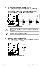
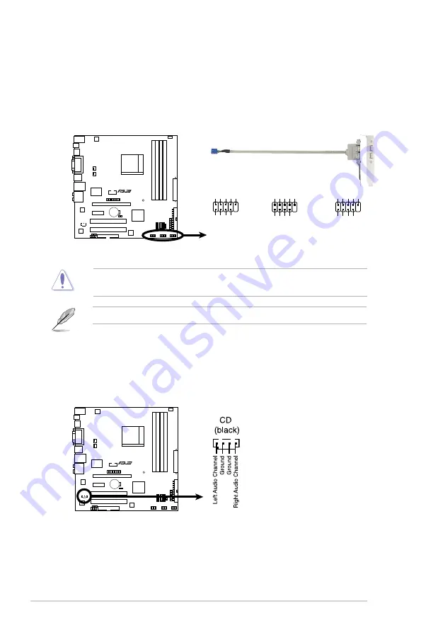
7.  USB connectors (10-1 pin USB78, USB910, USB1112)

These connectors are for USB 2.0 ports. Connect the USB module cable 

to any of these connectors, then install the module to a slot opening at the 

back of the system chassis. These USB connectors comply with USB 2.0 

specification that supports up to 480 Mbps connection speed.

Never connect a 1394 cable to the USB connectors. Doing so will damage the 

motherboard!

8.  Optical drive audio in connector (4-pin CD)

These connectors allow you to receive stereo audio input from sound sources 

such as a CD-ROM, TV tuner, or MPEG card. 

The USB 2.0 module is purchased separately.

M2N68-VM

M2N68-VM USB 2.0 Connectors

USB78

USB+5V USB_P8

-

USB_P8

+

GN

D

NC

USB+5V USB_P7

-

USB_P7

+

GN

D

1

USB910

USB+5V USB_P10-  GN

D

NC

USB+5V USB_P9

-

USB_P9

+

GN

D

1

USB1112

USB+5V USB_P12-  GN

D

NC

USB+5V USB_P1

1-

USB_P1

1+

GND

1

M2N68-VM

M2N68-VM Internal Audio Connector

Summary of Contents for M2N68-VM - Motherboard - Micro ATX

Page 1: ...Motherboard M2N68 VM ...

Page 2: ...ICULAR PURPOSE IN NO EVENT SHALL ASUS ITS DIRECTORS OFFICERS EMPLOYEES OR AGENTS BE LIABLE FOR ANY INDIRECT SPECIAL INCIDENTAL OR CONSEQUENTIAL DAMAGES INCLUDING DAMAGES FOR LOSS OF PROFITS LOSS OF BUSINESS LOSS OF USE OR DATA INTERRUPTION OF BUSINESS AND THE LIKE EVEN IF ASUS HAS BEEN ADVISED OF THE POSSIBILITY OF SUCH DAMAGES ARISING FROM ANY DEFECT OR ERROR IN THIS MANUAL OR PRODUCT SPECIFICATI...

Page 3: ...irection 1 8 1 5 3 Screw holes 1 8 1 6 Central Processing Unit CPU 1 9 1 6 1 Installing the CPU 1 9 1 6 2 Installing the heatsink and fan 1 11 1 7 System memory 1 13 1 7 1 Overview 1 13 1 7 2 Memory configurations 1 13 1 7 3 Installing a DIMM 1 19 1 7 4 Removing a DIMM 1 19 1 8 Expansion slots 1 20 1 8 1 Installing an expansion card 1 20 1 8 2 Configuring an expansion card 1 20 1 8 3 PCI slots 1 2...

Page 4: ...4 2 2 6 Configuration fields 2 14 2 2 7 Pop up window 2 14 2 2 8 Scroll bar 2 14 2 2 9 General help 2 14 2 3 Main menu 2 15 2 3 1 System Time 2 15 2 3 2 System Date 2 15 2 3 3 Legacy Diskette A 2 15 2 3 4 IDE Configuration 2 16 2 3 5 Primary IDE Master Slave 2 17 2 3 6 SATA1 SATA2 SATA3 2 19 2 3 7 System Information 2 20 2 4 Advanced menu 2 21 2 4 1 JumperFree Configuration 2 21 2 4 2 CPU Configur...

Page 5: ...2 38 2 7 Tools menu 2 40 2 7 1 ASUS EZ Flash 2 2 40 2 7 2 Express Gate 2 41 2 7 3 AI NET 2 2 41 2 8 Exit menu 2 42 Chapter 3 Software support 3 1 Installing an operating system 3 2 3 2 Support DVD information 3 2 3 2 1 Running the support DVD 3 2 3 2 2 Drivers menu 3 3 3 2 3 Utilities menu 3 4 3 2 4 Make Disk menu 3 6 3 2 5 Manual menu 3 7 3 2 6 ASUS Contact information 3 8 3 3 ASUS Express Gate 3...

Page 6: ...ause harmful interference to radio or television reception which can be determined by turning the equipment off and on the user is encouraged to try to correct the interference by one or more of the following measures Reorient or relocate the receiving antenna Increase the separation between the equipment and receiver Connect the equipment to an outlet on a circuit different from that to which the...

Page 7: ...ower supply is broken do not try to fix it by yourself Contact a qualified service technician or your retailer Operation safety Before installing the motherboard and adding devices on it carefully read all the manuals that came with the package Before using the product ensure that all cables are correctly connected and the power cables are not damaged If you detect any damage contact your dealer i...

Page 8: ...s chapter tells how to change system settings through the BIOS Setup menus Detailed descriptions of the BIOS parameters are also provided Chapter 3 Software support This chapter describes the contents of the support DVD that comes with the motherboard package Where to find more information Refer to the following sources for additional information and for product and software updates 1 ASUS website...

Page 9: ...ollow to complete a task Typography Bold text Indicates a menu or an item to select Italics Used to emphasize a word or a phrase Key Keys enclosed in the less than and greater than sign means that you must press the enclosed key Example Enter means that you must press the Enter or Return key Key1 Key2 Key3 If you must press two or more keys simultaneously the key names are linked with a plus sign ...

Page 10: ...x1 slot 2 x PCI slots Graphics Integrated Nvidia GeForce 7 Series Shader model 3 0 DirectX9 graphics processor Maximum shared memory of 256 MB Dual VGA output RGB DVI RGB HDMI Supports DVI D with max resolution 1920 x 1440 75MHz Supports RGB with max resolution 1920 x 1440 70MHz 32bpp 75MHz 16bpp Supports HDMITM Technology with HDCP compliant with max resolution 1920 x 1080 Note Due to the chipset...

Page 11: ...ace The actual boot time is subject to hardware configurations and product models ASUS Quiet Thermal Solution ASUS Q Fan ASUS EZ DIY ASUS CrashFree BIOS 3 ASUS EZ Flash 2 ASUS MyLogo 2 Rear panel I O 1 x LAN RJ 45 port 1 x HDMI port 1 x DVI port 6 x USB 2 0 1 1 ports 1 x VGA Out port 1 x PS 2 keyboard port 1 x S PDIF output port 1 x External SATA port 8 channel audio ports Internal I O connectors ...

Page 12: ...ased separately ASUS Overclocking Features SFS Stepless Frequency Selection from 200MHz to 300MHz at 1MHz increment Adjustable CPU Voltage at 0 025V increment ASUS C P R CPU Parameter Recall Support DVD contents Device drivers ASUS PC Probe II ASUS Live Update utility Anti virus software OEM version Supported OS Windows Vista Windows XP Form Factor uATX Form Factor 9 6 in x 9 6 in 24 4 cm x 24 4 c...

Page 13: ...1 Product introduction This chapter describes the motherboard features and the new technologies it supports ...

Page 14: ...cket AM2 Athlon 64 Sempron Athlon 64 X2 Athlon 64 FX Phenom FX Phenom AM2 processors with 2MB 1MB 512KB L2 cache which is based on 64 bit architecture It features 2000 1600 MT s HyperTransport Bus dual channel un buffered DDR2 1066 memory support and AMD Cool n Quiet Technology See page 1 9 for details AMD Cool n Quiet Technology The motherboard supports the AMD Cool n Quiet Technology which monit...

Page 15: ...ompressed all digital audio and video interface via a single cable and is HDCP compliant allowing playback of HD DVD Blu ray Disc and other protected content Dual channel DDR2 1066 DDR2 1066 memory provides great performance for 3D graphics and other memory demanding applications on next generation memory technology See page 1 13 for details DDR2 1066 is for AM2 only When you install two DDR2 1066...

Page 16: ... ten times faster than conventional 10 100 1000 Ethernet connections Gigabit LAN is the networking standard for the early future and is ideal for handling large amounts of data such as video audio and voice See page 1 22 for details 1 3 2 Innovative ASUS features ASUS Q Fan technology ASUS Q Fan technology intelligently adjusts CPU fan speeds according to system loading to ensure quiet cool and ef...

Page 17: ...striction on the use of Hazardous Substances RoHS This is in line with the ASUS vision of creating environment friendly and recyclable products and packaging to safeguard consumers health while minimizing the impact on the environment ASUS Express Gate Taking only 5 seconds to go online from bootup Express Gate is the one stop gateway to instant fun It s a unique motherboard built in OS You can ut...

Page 18: ...wer cord from the wall socket before touching any component Use a grounded wrist strap or touch a safely grounded object or a metal object such as the power supply case before handling components to avoid damaging them due to static electricity Hold components by the edges to avoid touching the ICs on them Whenever you uninstall any component place it on a grounded antistatic pad or in the bag tha...

Page 19: ...ASUS M2N68 VM 1 1 5 1 Motherboard layout 1 5 Motherboard overview ...

Page 20: ...ng the motherboard ensure that you place it into the chassis in the correct orientation The edge with external ports goes to the rear part of the chassis as indicated in the image below 1 5 3 Screw holes Place eight 8 screws into the holes indicated by circles to secure the motherboard to the chassis Place this side towards the rear of the chassis ...

Page 21: ...U is designed for the AM2 socket The CPU fits in only one correct orientation DO NOT force the CPU into the socket to prevent bending the connectors on the socket and damaging the CPU 1 6 1 Installing the CPU To install a CPU 1 Locate the CPU socket on the motherboard 2 Unlock the socket by pressing the lever sideways then lift it up to a 90 100 angle Ensure that the socket lever is lifted up to 9...

Page 22: ...nding the pins and damaging the CPU 5 When the CPU is in place push down the socket lever to secure the CPU The lever clicks on the side tab to indicate that it is locked 6 Install a CPU heatsink and fan following the instructions that came with the heatsink package Gold triangle Small triangle 7 Connect the CPU fan cable to the CPU_FAN connector on the motherboard Do not forget to connect the CPU...

Page 23: ...cket Ensure that you use only qualified heatsink and fan assembly The retention module base is already installed on the motherboard upon purchase You do not have to remove the retention module base when installing the CPU or installing other motherboard components If you purchased a separate CPU heatsink and fan assembly make sure that a Thermal Interface Material is properly applied to the CPU he...

Page 24: ...n bracket lock to the retention module base A clicking sound denotes that the retention bracket is in place 4 Push down the retention bracket lock on the retention mechanism to secure the heatsink and fan to the module base Ensure that the fan and heatsink assembly perfectly fits the retention mechanism module base Otherwise you cannot snap the retention bracket in place ...

Page 25: ...footprint compared to the 184 pin DDR DIMM DDR2 DIMMs are notched differently to prevent installation on a DDR DIMM socket The figure illustrates the location of the DDR2 DIMM sockets Channel Sockets Channel A DIMM_A1 and DIMM_A2 Channel B DIMM_B1 and DIMM_B2 Recommended memory configurations Sockets Mode DIMM_A1 DIMM_B1 DIMM_A2 DIMM_B2 Single Channel Populated Populated Dual channel 1 Populated P...

Page 26: ...than 3GB is recommended When you install two DDR2 1066MHz DIMMs as single channel configuraion the memory modules run at 800MHz as limitation 64 bit Windows XP Professional x64 Edition Windows Vista x64 Edition The motherboard can support 8 GB physical memory on the operating system listed below You may install a maximum of 2 GB DIMMs on each slot Qualified Vendors Lists QVL DDR2 533 MHz capabilit...

Page 27: ...acer SS AM4B5808CQJS7E0751C 1G Apacer AU01GE667C5KBGC N A Apacer DS AM4B5708GQJS7E0636B 1G Apacer AU01GE667C5KBGC 5 Apacer DS AM4B5708MIJS7E0627B 2G Apacer 78 A1G9O 9K4 5 Apacer DS AM4B5808CQJS7E0749B 1G Transcend 506010 4894 5 Elpida DS E5108AJBG 6E E 512MB ADATA M2OAD5G3H3160Q1C52 N A ADATA SS AD29608A8A 3EG20813 1G ADATA M2OAD5G314170Q1C58 N A ADATA DS AD29608A8A 3EG80814 2G ADATA M2OAD5H3J4170...

Page 28: ...28380 512MB Micron MT9HTF6472AY 80ED4 5 Micron SS 6ED22D9GKX ECC 1G Micron MT9HTF12872AY 800E1 6 Micron SS D9HNP 7YE22 ECC 1G Micron MT18HTF12872AY 80ED4 5 Micron DS 6TD22D9GKX ECC 1G Corsair XMS2 6400 4 Corsair DS Heat Sink Package 1G Corsair XMS2 6400 5 Corsair DS Heat Sink Package 512MB HY HYMP564U64CP8 S5 AB 5 Hynix SS HY5PS12821CFP S5 512MB Kingmax KLDC28F A8KI5 N A Kingmax SS KKA8FF1XF JFS 2...

Page 29: ...k Package 2G GEIL GX24GB6400DC 5 GEIL DS Heat Sink Package 2G GEIL GE28GB800C5QC 5 GEIL DS Heat Sink Package 2G GEIL GE28GB800C4QC 4 GEIL DS Heat Sink Package 2G GEIL GX22GB6400CUSC 4 GEIL DS Heat Sink Package 2G GEIL GE24GB800C4DC 4 GEIL DS Heat Sink Package 2G GEIL GE24GB800C5DC 5 GEIL DS Heat Sink Package 1G Super Talent T800UB1GC4 4 Super Talent DS Heat Sink Package 1G G SKILL F2 6400CL5D 2GBN...

Page 30: ...dules for overclocking may operate at a lower frequency than the vendor marked value Size Vendor Part No CL Chip Brand SS DS Chip No DIMM support A B C 512MB Kingston KHX8500D2 512 N A Kingston SS Heat Sink Package 512MB Kingston KVR1066D2N7 512 N A Elpida SS E5108AJBG 1J E 1G Kingston KHX8500D2K2 2GN N A Kingston DS Heat Sink Package 1G Kingston KVR1066D2N7 1G N A Elpida DS E5108AJBG 1J E 1G King...

Page 31: ...evere damage to both the motherboard and the components 1 7 4 Removing a DIMM To remove a DIMM 1 Simultaneously press the retaining clips outward to unlock the DIMM 2 Remove the DIMM from the socket Support the DIMM lightly with your fingers when pressing the retaining clips The DIMM might get damaged when it flips out with extra force A DDR2 DIMM is keyed with a notch so that it fits in only one ...

Page 32: ... use Keep the screw for later use 4 Align the card connector with the slot and press firmly until the card is completely seated on the slot 5 Secure the card to the chassis with the screw you removed earlier 6 Replace the system cover 1 8 2 Configuring an expansion card After installing the expansion card configure it by adjusting the software settings 1 Turn on the system and change the necessary...

Page 33: ...andard floppy disk controller 8 High precision event timer 9 Microsoft ACPI Compliant System 12 PS 2 Compatible Mouse 13 Numeric data processor 14 Primary IDE Channel 10 NVIDIA nForce PCI System Management 16 NVIDIA nForce 6800 LE 20 Microsoft UAA Bus Driver for High Definition Audio 21 Standard Enhanced PCI to USB Host Controller 21 Standard Dual Channel PCI IDE Controller 22 NVIDIA network Bus E...

Page 34: ...PCI Express x1 slot This motherboard supports PCI Express x1 network cards SCSI cards and other cards that comply with the PCI Express specifications The following figure shows a network card installed on the PCI Express x1 slot 1 8 5 PCI Express x16 slot This motherboard has supports PCI Express x16 graphic cards that comply with PCI Express specifications The figure shows a graphics card install...

Page 35: ...eep the cap on pins 2 3 for about 5 10 seconds then move the cap back to pins 1 2 4 Reinstall the battery 5 Plug the power cord and turn ON the computer 6 Hold down the Del key during the boot process and enter BIOS setup to re enter data Except when clearing the RTC RAM never remove the cap on CLRTC jumper default position Removing the cap will cause system boot failure You do not need to clear t...

Page 36: ... a 4 channel 6 channel or 8 channel audio configuration 6 Center Subwoofer port orange This port connects the center subwoofer speakers 7 Line In port light blue This port connects the tape CD DVD player or other audio sources 8 Line Out port lime This port connects a headphone or a speaker In 4 channel 6 channel and 8 channel configuration the function of this port becomes Front Speaker Out 9 Mic...

Page 37: ...sal Serial Bus USB ports are available for connecting USB 2 0 devices 12 External SATA port This port connects to an external Serial ATA hard disk drive Port Headset 2 channel 4 channel 6 channel 8 channel Light Blue Line In Line In Line In Line In Lime Line Out Front Speaker Out Front Speaker Out Front Speaker Out Pink Mic In Mic In Mic In Mic In Orange Center Subwoofer Center Subwoofer Black Rea...

Page 38: ...onnector Pin 5 on the connector is removed to prevent incorrect cable connection when using an FDD cable with a covered Pin 5 2 Chassis intrusion connector 4 1 pin CHASSIS This connector is for a chassis mounted intrusion detection sensor or switch Connect one end of the chassis intrusion sensor or switch cable to this connector The chassis intrusion sensor or switch sends a high level signal to t...

Page 39: ...the IDE connector is removed to match the covered hole on the Ultra DMA cable connector This prevents incorrect insertion when you connect the IDE cable Use the 80 conductor IDE cable for Ultra DMA 133 100 IDE devices If any device jumper is set as Cable Select ensure that all other device jumpers have the same setting Drive jumper setting Mode of device s Cable connector Single device Cable Selec...

Page 40: ...ives you can create a RAID 0 RAID 1 RAID 5 RAID 10 and JBOD configuration through the onboard controllers and one ESATA Install the Windows XP Service Pack 1 before using Serial ATA For detailed instructions on how to configure RAID 0 RAID 1 RAID 5 and RAID 10 and JBOD refer to the RAID manual in the support CD If you intend to create a Serial ATA RAID set using these connectors set the SATA Mode ...

Page 41: ...al Sony Philips Digital Interface S PDIF port s Connect the S PDIF module cable to this connector then install the module to a slot opening at the back of the system chassis Only CPU Fan supports Q Fan The S PDIF module is purchased separately M2N68 VM M2N68 VM Fan Connectors CHA_FAN GND Rotation 12V GND Rotation 12V PWR_FAN CPU_FAN M2N68 VM 5V SPDIFOUT GND SPDIF_OUT M2N68 VM Digital Audio Connect...

Page 42: ...ever connect a 1394 cable to the USB connectors Doing so will damage the motherboard 8 Optical drive audio in connector 4 pin CD These connectors allow you to receive stereo audio input from sound sources such as a CD ROM TV tuner or MPEG card The USB 2 0 module is purchased separately M2N68 VM M2N68 VM USB 2 0 Connectors USB78 USB 5V USB_P8 USB_P8 GND NC USB 5V USB_P7 USB_P7 GND 1 USB910 USB 5V U...

Page 43: ...tion front panel audio module to this connector to avail of the motherboard high definition audio capability If you want to connect a high definition front panel audio module to this connector ensure that the Front Panel Type item in the BIOS is set to HD Audio if you want to connect an AC 97 front panel audio module to this connector set the item to AC97 See page 2 28 for details The serial port ...

Page 44: ... boot up if the power is inadequate Do not forget to connect the 4 pin ATX 12 V power plug Otherwise the system will not boot up We recommend that you use a PSU with higher power output when configuring a system with more power consuming devices The system may become unstable or may not boot up if the power is inadequate If you are uncertain about the minimum power supply requirement for your syst...

Page 45: ...pports devices such as a printer LPT standardizes as IEEE 1284 which is the parallel port interface on IBM PC compatible computers M2N68 VM M2N68 VM Parallel Port Connector LPT STB AFD PD0 ERR PD1 INIT PD2 SLIN PD3 GND PD4 1 GND PD7 PD6 PD5 GND GND GND ACK GND BUSY PE SLCT GND GND ...

Page 46: ...IDE LED lights up or flashes when data is read from or written to the HDD System warning speaker 4 pin SPEAKER This 4 pin connector is for the chassis mounted system warning speaker The speaker allows you to hear system beeps and warnings Power Soft off button 2 pin PWRSW This 2 pin connector is for the system power button Pressing the power button turns the system ON or puts the system in SLEEP o...

Page 47: ...2 This chapter tells how to change the system settings through the BIOS Setup menus Detailed descriptions of the BIOS parameters are also provided BIOS setup ...

Page 48: ...on these utilities Save a copy of the original motherboard BIOS file to a bootable floppy disk in case you need to restore the BIOS in the future Copy the original motherboard BIOS using the ASUS Update or AFUDOS utilities 2 1 1 Creating a bootable floppy disk 1 Do either one of the following to create a bootable floppy disk DOS environment a Insert a 1 44MB floppy disk into the drive b At the DOS...

Page 49: ...disk drive b Click from the Windows desktop then select Computer c Right click Floppy Disk Drive then click Format to display the Format 3 1 2 Floppy dialog box d Select the Create an MS DOS startup disk check box e Click Start 2 Copy the original or the latest motherboard BIOS file to the bootable floppy disk ...

Page 50: ...ash 2 and press Enter to enable it You can switch between drives by pressing Tab before the correct file is found Then press Enter 4 When the correct BIOS file is found EZ Flash 2 performs the BIOS update process and automatically reboots the system when done 1 Insert the floppy disk USB flash disk that contains the BIOS file to the floppy disk drive or the USB port Press Alt F2 during POST to dis...

Page 51: ...en at the prompt type afudos o filename where the filename is any user assigned filename not more than eight alphanumeric characters for the main filename and three alphanumeric characters for the extension name A afudos oOLDBIOS1 rom Ensure that the floppy disk is not write protected and has at least 1024KB free space to save the file The succeeding BIOS screens are for reference only The actual ...

Page 52: ...se restart your computer A 2 Copy the AFUDOS utility afudos exe from the motherboard support DVD to the bootable floppy disk you created earlier 3 Boot the system in DOS mode then at the prompt type afudos i filename where filename is the latest or the original BIOS file on the bootable floppy disk A afudos iM2N68VM ROM Write the BIOS filename on a piece of paper You need to type the exact BIOS fi...

Page 53: ... flash disk to M2N68VM ROM Recovering the BIOS from a floppy disk To recover the BIOS from a floppy disk 1 Turn on the system 2 Insert the floppy disk with the original or updated BIOS file to the floppy disk drive 3 The utility displays the following message and automatically checks the floppy disk for the original or updated BIOS file Bad BIOS checksum Starting BIOS recovery Checking for floppy ...

Page 54: ...rting BIOS recovery Checking for floppy 4 Restart the system after the utility completes the updating process The recovered BIOS may not be the latest BIOS version for this motherboard Visit the ASUS website www asus com to download the latest BIOS file Only the USB flash disk with FAT 32 16 format and single partition can support ASUS CrashFree BIOS 3 The device size should be smaller than 8GB DO...

Page 55: ...e save and update the motherboard BIOS in Windows environment The ASUS Update utility allows you to Save the current BIOS file Download the latest BIOS file from the Internet Update the BIOS from an updated BIOS file Update the BIOS directly from the Internet and View the BIOS version information This utility is available in the support DVD that comes with the motherboard package ASUS Update requi...

Page 56: ... Next Updating the BIOS through the Internet To update the BIOS through the Internet 1 Launch the ASUS Update utility from the Windows desktop by clicking Start Programs ASUS ASUSUpdate ASUSUpdate The ASUS Update main window appears 2 Select Update BIOS from the Internet option from the drop down menu then click Next ...

Page 57: ... a file option from the drop down menu then click Next 3 Locate the BIOS file from the Open window then click Open 4 Follow the screen instructions to complete the update process 4 From the FTP site select the BIOS version that you wish to download Click Next 5 Follow the screen instructions to complete the update process The ASUS Update utility is capable of updating itself through the Internet A...

Page 58: ...am Press Del during the Power On Self Test POST to enter the Setup utility Otherwise POST continues with its test routines If you wish to enter Setup after POST restart the system by pressing Ctrl Alt Delete or by pressing the reset button on the system chassis You can also restart by turning the system off and then back on Do this last option only if the first two failed The Setup program is desi...

Page 59: ... advanced system settings Power For changing the advanced power management APM configuration Boot For changing the system boot configuration Tools For setting EZ Flash 2 Exit For selecting the exit options and loading default settings To select an item on the menu bar press the right or left arrow key on the keyboard until the desired item is highlighted Use ENTER TAB or SHIFT TAB to select a fiel...

Page 60: ...n is a brief description of the selected item Some of the navigation keys differ from one screen to another 2 2 7 Pop up window Select a menu item then press Enter to display a pop up window with the configuration options for that item 2 2 8 Scroll bar A scroll bar appears on the right side of a menu screen when there are items that do not fit on the screen Press the Up Down arrow keys or Page Up ...

Page 61: ...ay xx xx xxxx Allows you to set the system date 2 3 3 Legacy Diskette A 1 44M 3 5 in Sets the type of floppy drive installed Configuration options Disabled 720K 3 5 in 1 44M 3 5 in 360K 5 25 pin 1 2M 5 25 pin 2 88M 3 5 pin System Time 21 50 03 System Date Mon 05 12 2008 Legacy Diskette A 1 44M 3 5in IDE Configuration Primary IDE Master Not Detected Primary IDE Slave Not Detected SATA1 ST380011AS S...

Page 62: ...A Devices Enabled Allows you to disable or set the Serial ATA devices Configuration options Enabled Disabled ESATA Mode select SATA Mode Allows you to select the SATA Mode Configuration options SATA Mode RAID Mode AHCI Mode The following items appears only when the SATA Mode select item is set to RAID Mode ESATA Primary Master Slave Channel Disabled Allows you to disable or enable the Extermal Ser...

Page 63: ...talled in the system Type Auto Selects the type of IDE drive Setting to Auto allows automatic selection of the appropriate IDE device type Select CDROM if you are specifically configuring a CD ROM drive Select ARMD ATAPI Removable Media Device if your device is either a ZIP LS 120 or MO drive Configuration options Not Installed Auto CDROM ARMD LBA Large Mode Auto Enables or disables the LBA mode S...

Page 64: ...bles the S M A R T Self Monitoring and Reporting Technology capability of your hard drive This features allows your system to report read write errors of the hard drive and to issue warnings when a third party hardware monitor utility is installed Configuration options Auto Disabled Enabled 32Bit Data Transfer Enabled Enables or disables 32 bit data transfer Configuration options Disabled Enabled ...

Page 65: ...uration options Disabled Auto Block Multi sector Transfer M Auto Enables or disables data multi sectors transfers When set to Auto the data transfer from and to the device occurs multiple sectors at a time if the device supports multi sector transfer feature When set to Disabled the data transfer from and to the device occurs one sector at a time Configuration options Disabled Auto PIO Mode Auto S...

Page 66: ...to Disabled Enabled 32Bit Data Transfer Enabled Enables or disables 32 bit data transfer Configuration options Disabled Enabled 2 3 7 System Information This menu gives you an overview of the general system specifications The BIOS automatically detects the items in this menu AMIBIOS Version 0301 Build Date 06 06 08 Processor Type AMD Sempron tm Processor 3200 Speed 1800MHz Count 1 System Memory In...

Page 67: ...allows you to set overclocking parameters automatically MANUAL allows you to individually set overclocking parameters Standard loads the standard settings for the system Overclock Profile loads overclocking profiles with optimal parameters for stability when overclocking Configure System Frequency CPU Overclocking Auto PCIE Overclocking Auto CPU Ratio and Voltage Processor Frequency Multiplier Aut...

Page 68: ...he PCIE Overclocking Configuration options Auto Manual The following item appears only when the CPU Overclocking item is set to MANUAL Processor Frequency Multiplier Auto Allows you to select Processor frequency Configuration options Auto x4 0 800 MHz x5 0 1000 MHz x6 0 1200 MHz x7 0 1400 MHz x8 0 1600 MHz x9 0 1800 MHz Processor Voltage Auto Allows you to select the Processor voltage or set it to...

Page 69: ...ming Mode Auto Allows you to set the DRAM timing mode Configuration options Auto DCT 0 Memory Over Voltage Auto Allows you to set the memory over voltage The value ranges from 1 85000V to 2 24375V with a 0 00625V interval Configuration options Auto Chipset Over Voltage Auto Allows you to set the chipset over voltage Configuration options Auto 50mv 100mv 150mv The following two items appear only wh...

Page 70: ...ool n Quiet Enabled Allows you to enable or disable the generation of ACPI_PPC _PSS and _PCT objects Configuration options Disabled Enabled This option should remain disabled for the normal operation The driver developer may enable it for testing purpose CPU Configuration Module Version 13 29 AGESA Version 3 1 8 0 Physical Count 1 Logical Count 1 AMD Athlon tm Processor 3200 Revision F2 Cache L1 1...

Page 71: ...ory Options Information Memory Configuration Enable Bank Memory Interleaving Memory Configuration Bank Interleaving Disabled Channel Interleaving Disabled Enable Clock to All DIMMs Disabled MemClk Tristate C3 ATLVID Disabled Memory Hole Remapping Enabled DCT Unganged Mode Auto Power Down Enable Enabled Bank Interleaving Disabled Allows you to enable the bank memory interleaving Configuration optio...

Page 72: ...Clk Tristate C3 ALTVID Configuration options Disabled Enabled Memory Hole Remapping Enabled Enables or disables the memory remapping around memory hole Configuration options Disabled Enabled DCT Unganged Mode Auto Allows you to enable or disable Unganged mode Configuration options Auto Always Power Down Enable Enabled Enables or disables the DDR power down mode Configuration options Disabled Enabl...

Page 73: ...5 12us 10 2us 20 5us 41 0us 81 9us 163 8us 327 7us 655 4us Data L2 L3 Cache BG Scrub Disabled Disables or sets the Data L2 L3 Cache BG Scrub This item allows the cache RAM to be corrected when idle Configuration options Disabled 40ns 80ns 160na 320ns 640ns 1 28us 2 56us 5 12us 10 2us 20 5us 41 0us 81 9us 163 8us 327 7us 655 4us Data Cache BG Scrub Disabled Disables or sets the Data Cache BG Scrub ...

Page 74: ... you to set the iGPU Frame Buffer Size Configuration options 128MB AZALIA AUDIO Enabled Allows you to set or disable the AZALIA AUDIO Configuration options Disabled Enabled Front Panel Select HD Audio Allows you to set HD Audio mode Configuration options AC97 HD Audio OnBoard LAN Auto Allows you to set or disable the OnBoard LAN Configuration options Auto Disabled OnBoard LAN Boot ROM Disabled All...

Page 75: ...lect the Serial Port1 base address Configuration options Disabled 3F8 IRQ4 2F8 IRQ3 3E8 IRQ4 2E8 IRQ3 Parallel Port Address 378 Allows you to select the Parallel Port base addresses Configuration options Disabled 378 278 3BC Parallel Port Mode Normal Allows you to select the Parallel Port mode Configuration options Normal EPP ECP EPP ECP Parallel Port IRQ IRQ7 Configuration options IRQ5 IRQ7 Allow...

Page 76: ... BIOS assigns an IRQ to PCI VGA card if the card requests for an IRQ When set to No BIOS does not assign an IRQ to the PCI VGA card even if requested Configuration options No Yes Palette Snooping Disabled When set to Enabled the palete snooping feature informs the PCI devices that an ISA graphics device is installed in the system so that the latter can function correctly Configuration options Disa...

Page 77: ...rives Setting to Auto allows the system to detect the presence of USB devices at startup If detected the USB controller legacy mode is enabled If no USB device is detected the legacy USB support is disabled Configuration options Disabled Enabled Auto The Module Version and USB Devices Enabled items show the auto detected values If no USB device is detected the item shows None 2 4 6 USB Configurati...

Page 78: ...2 32 Chapter 2 BIOS setup USB 2 0 Controller Mode HiSpeed Allows you to configure the USB 2 0 controller in HiSpeed 480 Mbps or Full Speed 12 Mbps Configuration options Full Speed HiSpeed ...

Page 79: ...pend to RAM sleep state default In S3 sleep state the system appears to be off and consumes less power than in the S1 state When signaled by a wake up device or event the system resumes to its working state exactly where it was left off Auto Detected by OS 2 5 2 ACPI Version Features Disabled Allows you to add more tables for Advanced Configuration and Power Interface ACPI features Configuration o...

Page 80: ...n the system through a PCI LAN or modem card This feature requires an ATX power supply that provides at least 1A on the 5VSB lead Configuration options Disabled Enabled Power On By Ring Disabled Enable or disable RI to generate a wake event Configuration options Disabled Enabled Power On By PS 2 KB MS Disabled Enable or disable PS 2 Keyboard Mouse to generate a wake event Configuration options Dis...

Page 81: ... the detected speed Chassis Fan Speed xxxxRPM or N A or Ignored The onboard hardware monitor automatically detects and displays the chassis fan speed in rotations per minute RPM If the fan is not connected to the chassis the specific field shows N A Select Ignored if you do not wish to display the detected speed Power Fan Speed xxxxRPM or Ignored The onboard hardware monitor automatically detects ...

Page 82: ...oot Settings Configuration Security Select Screen Select Item Change Option F1 General Help F10 Save and Exit ESC Exit 2 6 1 Boot Device Priority Boot Device Priority 1st Boot Device 1st FLOPPY DRIVE 2nd Boot Device Hard Drive 3rd Boot Device ATAPI CD ROM 1st xxth Boot Device 1st Floppy Drive These items specify the boot device priority sequence from the available devices The number of device item...

Page 83: ...em When set to Disabled BIOS performs all the POST items Configuration options Disabled Enabled Full Screen Logo Enabled This allows you to enable or disable the full screen logo display feature Configuration options Disabled Enabled Add On ROM Display Mode Force BIOS Sets the display mode for option ROM Configuration options Force BIOS Keep Current Bootup Num Lock On Allows you to select the powe...

Page 84: ...nter to change password Enter again to disabled password Change Supervisor Password Select this item to set or change the supervisor password The Supervisor Password item on top of the screen shows the default Not Installed After you set a password this item shows Installed To set a Supervisor Password 1 Select the Change Supervisor Password item and press Enter 2 From the password box type a pass...

Page 85: ...nd press Enter 2 On the password box that appears type a password composed of at least six letters and or numbers then press Enter 3 Confirm the password when prompted The message Password Installed appears after you set your password successfully To change the user password follow the same steps as in setting a user password Clear User Password Select this item to clear the user password Password...

Page 86: ... the left right arrow key to select between Yes or No then press Ok to confirm your choice ASUSTek EZ Flash 2 BIOS ROM Utility V3 06 Current ROM Update ROM A Note Enter Select or Load B Backup ESC Exit Tab Switch Up Down Home End Move FLASH TYPE MXIC 25L8005 PATH A BOARD M2N68 VM VER 0301 DATE 06 06 08 BOARD Unknown VER Unknown DATE Unknown Press ENTER to run the utility to select and update BIOS ...

Page 87: ...e for user action Configuration options Prompt User 1 second 3 seconds 5 seconds 10 seconds 15 seconds 20 seconds 30 seconds Reset User Data No Allows you to clear Express Gate s user data Configuration options No Reset The first time wizard will run again when you enter the Express Gate environment after clearing its settings 2 7 3 AI NET 2 Select Screen Select Item Change Option F1 General Help ...

Page 88: ...tile RAM Exit Save Changes Once you are finished making your selections choose this option from the Exit menu to ensure the values you selected are saved to the CMOS RAM An onboard backup battery sustains the CMOS RAM so it stays on even when the PC is turned off When you select this option a confirmation window appears Select OK to save changes and exit 2 8 Exit menu Pressing Esc does not immedia...

Page 89: ...3 Software support This chapter describes the contents of the support DVD that comes with the motherboard package ...

Page 90: ...indows 2000 operating system OS hence ASUS support DVD v406 02 and later version cannot support Windows 2000 OS If you want to use Windows 2000 OS on this motherboard download the older version driver package from the ASUS website http support asus com download download aspx Language en us model M2N68 VM 20HDMI type drivers 3 2 Support DVD information The support DVD that came with the motherboard...

Page 91: ... Internet Security 2008 Installs the Norton Internet Security 2008 Nvidia Chipset Program Driver Installs the Nvidia chipset program driver AMD Cool n Quiet Driver Installs the AMD Cool n Quiet driver VIA Audio Driver Installs the VIA audio driver The screen display and driver options may vary depending on the operating system version If Autorun is NOT enabled in your computer browse the contents ...

Page 92: ...update the motherboard BIOS in a Windows environment This utility requires an Internet connection either through a network or an Internet Service Provider ISP ASUS PC Probe II This smart utility monitors the fan speed CPU temperature and system voltages and alerts you of any detected problems This utility helps you keep your computer in healthy operating condition Adobe Acrobat Reader 8 Installs t...

Page 93: ...rel MediaOne plus application to easily manage edit share and protect your multimedia data Ulead Photolmpact 12 SE Installs the Photolmpact image editing software You can also install the following utilities from the ASUS Superb Software Library DVD CyberLink PowerBackup Installs CyberLink PowerBackup to back up and restore your data easily WinZip 11 Installs the Winzip utility for easy file compr...

Page 94: ...er Visit the Microsoft website www microsoft com for updates 3 2 4 Make Disk menu The Make Disk menu allows you to make a RAID driver disk NVIDIA 32bit XP AHCI Driver Allows you to create the NVIDIA AHCI Driver disk for Windows 32 bit OS NVIDIA 64bit XP AHCI Driver Allows you to create the NVIDIA AHCI Driver disk for Windows 64 bit XP OS NVIDIA Vista32 AHCI Driver Allows you to create the NVIDIA A...

Page 95: ...Driver Allows you to create the NVIDIA SATA RAID Driver disk for Windows 32 bit Vista OS NVIDIA 64bit Vista SATA RAID Driver Allows you to create the NVIDIA SATA RAID Driver disk for Windows 64 bit Vista OS 3 2 5 Manual menu The Manual menu contains a list of supplementary user manuals Click an item to open the folder of the user manual Most user manual files are in Portable Document Format PDF In...

Page 96: ...3 Chapter 3 Software support 3 2 6 ASUS Contact information Click the Contact tab to display the ASUS contact information You can also find this information on the inside front cover of this user guide ...

Page 97: ...led onboard SATA ports only All onboard extended SATA ports and external SATA ports are NOT supported See chapter 2 for the exact location of onboard SATA ports ASUS Express Gate supports installation on USB HDDs and Flash drives but the software performance may be slower than installed on SATA HDDs To install Express Gate on your computer 1 Place the support CD DVD to the optical drive The Driver...

Page 98: ...ot to OS button As you move the mouse or type a key the countdown stops and the timer disappears so you can take your time to make a selection The Express Gate Environment The very first time you enter the Express Gate environment by launching either web or Skype from the first screen a first time wizard will guide you through basic Express Gate configurations Basic configurations include language...

Page 99: ...lso right click anywhere on the desktop to bring up a menu of softwares The red triangle on an software icon in the LaunchBar denotes that the software is already running This means that you can switch to it without any delay In the rare case where an software stops responding right click on its icon to force close it Knowing the Express Gate hot keys Here is a list of common used hot keys for Exp...

Page 100: ...s may differ from motherboards You can connect the LAN cable to either port and Express Gate will automatically use the connected port Also specify whether each port uses DHCP most common or static IP For PPPoE and wireless optional set the login credentials user name password SSID etc as well Environment Settings This function allows you to clear the Express Gate settings as well as any personal ...

Page 101: ...g tool Start the Skype software which lets you call other people on Skype for free as well as offering affordable high quality voice communications to phones all over the world Opens Configuration Panel which lets you specify network settings and other preferences In the rare case that one of the above softwares stops responding you can right click on its icon and then select Close to force it to ...

Page 102: ...ress Gate Click to open Express Gate Help Click to bring up power options window to boot to OS restart or power down This window is also shown when you press Ctrl Alt Del on the keyboard Power off Enter OS Cancel and return to Express Gate Restart Check to save user profile How Do I Get on to the Internet If Internet doesn t seem to be working in the Express Gate environment check the following 1 ...

Page 103: ...ess Gate will automatically use whichever port LAN1 or LAN2 is connected If you plug the network cable into a different port while Express Gate is running e g move the cable from LAN1 to LAN2 you may need to press the Refresh button to detect the change The most common scenario is for your computer to automatically obtain network settings i e DHCP If this is the case you don t need to click Setup ...

Page 104: ...cable dial up and establish the PPPoE connection When PPPoE is enabled the port it uses will automatically be unchecked and grayed out Using the Photo Manager Express Gate provides a easy to use Photo Manager that allows you to view pictures stored in your hard drive or external storage devices such as USB dongles card readers or optical disks You can view pictures in thumbnail view in an enlarged...

Page 105: ...ick the Express Gate setup file to start software update 2 Asoftware update confirmation dialog box appears Click Yes to continue 3 The InstallShield Wizard for Express Gate appears Click Next to continue 4 Follow the screen instructions to complete installation Repairing Express Gate In case Express Gate cannot start normally you can repair Express Gate by reinstalling the software or using the r...

Page 106: ...3 18 Chapter 3 Software support ...

Reviews: