background image

1-10

Chapter 1: Product introduction

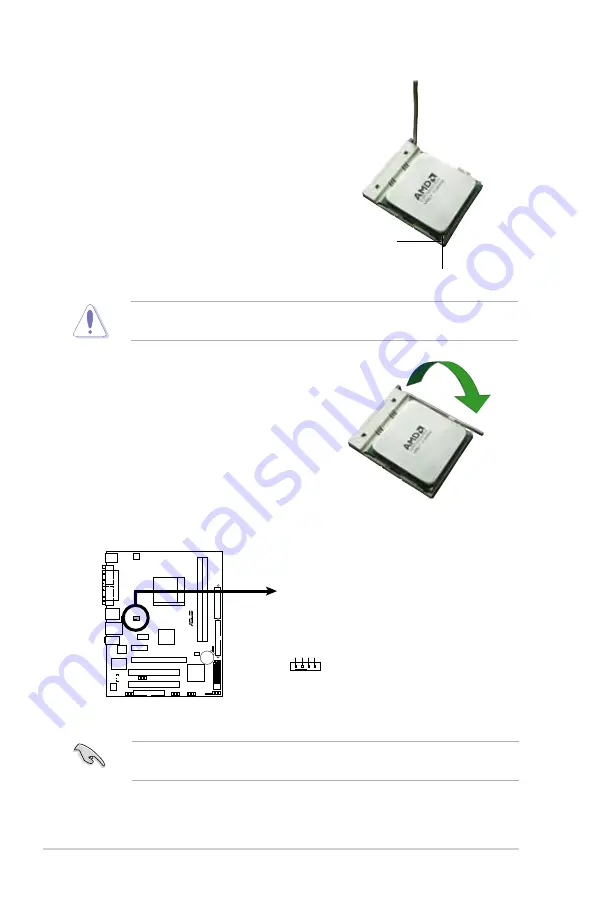
3.  Position the CPU above the socket 

such that the CPU corner with the 

gold triangle matches the  socket 

corner with a small triangle.

4.  Carefully insert the CPU into the 

socket until it fits in place.

The CPU fits only in one correct orientation. DO NOT force the CPU into the 

socket to prevent bending the pins and damaging the CPU!

5.  When the CPU is in place, push 

down the socket lever to secure the 

CPU. The lever clicks on the side 

tab to indicate that it is locked.

6.  Install a CPU heatsink and fan 

following the instructions that came 

with the heatsink package.

Gold triangle

Small triangle

7.  Connect the CPU fan cable to the CPU_FAN connector on the motherboard.

Do not forget to connect the CPU fan connector! Hardware monitoring errors 

can occur if you fail to plug this connector.

M2A-MX

R

M2A-MX CPU Fan Connector

CPU_FAN

GND CPU F

AN PWR

CPU F

AN IN

CPU F

AN PWM

Summary of Contents for M2A-MX

Page 1: ...Motherboard M2A MX ...

Page 2: ...RTICULAR PURPOSE IN NO EVENT SHALL ASUS ITS DIRECTORS OFFICERS EMPLOYEES OR AGENTS BE LIABLE FOR ANY INDIRECT SPECIAL INCIDENTAL OR CONSEQUENTIAL DAMAGES INCLUDING DAMAGES FOR LOSS OF PROFITS LOSS OF BUSINESS LOSS OF USE OR DATA INTERRUPTION OF BUSINESS AND THE LIKE EVEN IF ASUS HAS BEEN ADVISED OF THE POSSIBILITY OF SUCH DAMAGES ARISING FROM ANY DEFECT OR ERROR IN THIS MANUAL OR PRODUCT SPECIFICA...

Page 3: ...5 3 Screw holes 1 8 1 6 Central Processing Unit CPU 1 9 1 6 1 Installing the CPU 1 9 1 6 2 Installing the heatsink and fan 1 11 1 7 System memory 1 13 1 7 1 Overview 1 13 1 7 2 Memory configurations 1 13 1 7 3 Installing a DIMM 1 19 1 7 4 Removing a DIMM 1 19 1 8 Expansion slots 1 20 1 8 1 Installing an expansion card 1 20 1 8 2 Configuring an expansion card 1 20 Interrupt assignments 1 21 1 8 3 P...

Page 4: ... 4 Menu items 2 13 2 2 5 Sub menu items 2 13 2 2 6 Configuration fields 2 13 2 2 7 Pop up window 2 13 2 2 8 General help 2 13 2 3 Main menu 2 14 2 3 1 System Time 2 14 2 3 2 System Date 2 14 2 3 3 Legacy Diskette A 2 14 2 3 4 Primary IDE Master Slave 2 15 2 3 5 SATA1 SATA2 SATA3 and SATA4 2 16 2 3 6 IDE Configuration 2 17 2 3 7 System Information 2 18 2 4 Advanced menu 2 19 2 4 1 JumperFree Config...

Page 5: ...1 Boot Device Priority 2 31 2 6 2 Boot Settings Configuration 2 32 2 6 3 Security 2 33 2 7 Exit menu 2 35 Chapter 3 Software support 3 1 Installing an operating system 3 2 3 2 Support CD information 3 2 3 2 1 Running the support CD 3 2 3 2 2 Drivers menu 3 3 3 2 3 Utilities menu 3 4 3 2 4 Make Disk menu 3 5 3 2 5 Manual menu 3 5 3 2 6 ASUS Contact information 3 6 3 2 7 Other information 3 6 ...

Page 6: ...ause harmful interference to radio or television reception which can be determined by turning the equipment off and on the user is encouraged to try to correct the interference by one or more of the following measures Reorient or relocate the receiving antenna Increase the separation between the equipment and receiver Connect the equipment to an outlet on a circuit different from that to which the...

Page 7: ...e power supply is broken do not try to fix it by yourself Contact a qualified service technician or your retailer Operation safety Before installing the motherboard and adding devices on it carefully read all the manuals that came with the package Before using the product make sure all cables are correctly connected and the power cables are not damaged If you detect any damage contact your dealer ...

Page 8: ...chapter tells how to change system settings through the BIOS Setup menus Detailed descriptions of the BIOS parameters are also provided Chapter 3 Software support This chapter describes the contents of the support CD DVD that comes with the motherboard package Where to find more information Refer to the following sources for additional information and for product and software updates 1 ASUS websit...

Page 9: ...that you MUST follow to complete a task Typography Bold text Indicates a menu or an item to select Italics Used to emphasize a word or a phrase Key Keys enclosed in the less than and greater than sign means that you must press the enclosed key Example Enter means that you must press the Enter or Return key Key1 Key2 Key3 If you must press two or more keys simultaneously the key names are linked wi...

Page 10: ...Graphics Integrated ATI Radeon X1200 VPU graphics Note Max UMA memory is up to 256 MB Storage AMD SB600 chipset supports 1 x Ultra DMA 133 100 66 interface for two 2 hard disk drives 4 x Serial ATA 3 Gb s hard disk drives supporting RAID 0 RAID 1 and RAID 0 1 configurations High Definition Audio Realtek ALC662 High Definition Audio 6 channel CODEC Supports Jack deteck and Anti Pop Function Support...

Page 11: ...n connector 4 x Serial ATA connectors 3 x USB 2 0 connectors for 6 additional USB 2 0 ports 24 pin ATX power connector 4 pin x ATX 12V power connector 1 x System panel connector Power Requirement ATX power supply with 24 pin and 4 pin 12 V plugs ATX 12 V 2 0 compliant Accessories 1 x Serial ATA signal cable 1 x SATA power cable 1 x UltraDMA 133 100 66 1 x Floppy disk drive cable 1 x I O Shield Use...

Page 12: ...xii ...

Page 13: ...1 Product introduction This chapter describes the motherboard features and the new technologies it supports ...

Page 14: ... AMD socket AM2 AM2 single core Athlon 64 Sempron and dual core Athlon 64 X2 Athlon 64 FX processors with 2 MB 1 MB 512 KB L2 cache which is based on 64 bit architecture It features 2000 1600 MT s HyperTransport Bus dual channel un buffered DDR2 800 memory support and AMD Cool n Quiet Technology See page 1 9 for details AMD Cool n Quiet Technology The motherboard supports the AMD Cool n Quiet Tech...

Page 15: ... to boost system performance eliminating bottlenecks with peak bandwidths of up to 12 8 GB s See page 1 13 for details PCI Express interface The motherboard fully supports PCI Express the latest I O interconnect technology that speeds up the PCI bus PCI Express features point to point serial interconnections between devices and allows higher clockspeeds by carrying data in packets This high speed ...

Page 16: ...e with USB 1 1 See pages 1 25 1 27 and 1 32 for details ASUS Q Fan technology The ASUS Q Fan technology smartly adjusts the CPU fan speeds according to the system loading to ensure quiet cool and efficient operation See page 2 30 for details ASUS CrashFree BIOS 2 This feature allows you to restore the original BIOS data from the support CD in case when the BIOS codes and data are corrupted This pr...

Page 17: ... default settings in case the system hangs due to overclocking When the system hangs due to overclocking C P R eliminates the need to open the system chassis and clear the RTC data Simply shut down and reboot the system and the BIOS automatically restores the CPU default setting for each parameter See page 1 24 for details ...

Page 18: ...ower cord from the wall socket before touching any component Use a grounded wrist strap or touch a safely grounded object or a metal object such as the power supply case before handling components to avoid damaging them due to static electricity Hold components by the edges to avoid touching the ICs on them Whenever you uninstall any component place it on a grounded antistatic pad or in the bag th...

Page 19: ... 64 bit 240 pin module DDR2 DIMM_B1 64 bit 240 pin module PCI2 PCI1 PCIEX16 PCIEX1_1 AUDIO F_USB34 LAN1_USB12 CLRTC PRI_IDE CR2032 3V Lithium Cell CMOS Power CHASSIS SPDIF_OUT SATA4 SATA3 SATA1 SATA2 8Mb BIOS USB910 F_PANEL USB78 USB56 AMD 690V AAFP CD ALC662 Super I O Attansic L1 ICS 951462AGLF COM1 COM2 PARALLEL PORT ATX12V CPU_FAN CHA_FAN PS2_USBPW AMD SB600 M2A MX R ...

Page 20: ...g the motherboard make sure that you place it into the chassis in the correct orientation The edge with external ports goes to the rear part of the chassis as indicated in the image below 1 5 3 Screw holes Place six 6 screws into the holes indicated by circles to secure the motherboard to the chassis Place this side towards the rear of the chassis ...

Page 21: ...is designed for the AM2 socket The CPU fits in only one correct orientation DO NOT force the CPU into the socket to prevent bending the connectors on the socket and damaging the CPU 1 6 1 Installing the CPU To install a CPU 1 Locate the CPU socket on the motherboard 2 Unlock the socket by pressing the lever sideways then lift it up to a 90 100 angle Make sure that the socket lever is lifted up to ...

Page 22: ... damaging the CPU 5 When the CPU is in place push down the socket lever to secure the CPU The lever clicks on the side tab to indicate that it is locked 6 Install a CPU heatsink and fan following the instructions that came with the heatsink package Gold triangle Small triangle 7 Connect the CPU fan cable to the CPU_FAN connector on the motherboard Do not forget to connect the CPU fan connector Har...

Page 23: ...t Make sure that you use only qualified heatsink and fan assembly The retention module base is already installed on the motherboard upon purchase You do not have to remove the retention module base when installing the CPU or installing other motherboard components If you purchased a separate CPU heatsink and fan assembly make sure that a Thermal Interface Material is properly applied to the CPU he...

Page 24: ...bracket lock to the retention module base A clicking sound denotes that the retention bracket is in place 4 Push down the retention bracket lock on the retention mechanism to secure the heatsink and fan to the module base Make sure that the fan and heatsink assembly perfectly fits the retention mechanism module base otherwise you cannot snap the retention bracket in place ...

Page 25: ...e physical dimensions as a DDR DIMM but has a 240 pin footprint compared to the 184 pin DDR DIMM DDR2 DIMMs are notched differently to prevent installation on a DDR DIMM socket The figure illustrates the location of the DDR2 DIMM sockets Channel Sockets Channel A DIMM_A1 Channel B DIMM_B1 Recommended memory configurations Sockets Mode DIMM_A1 DIMM_B1 Single Channel Populated Populated Dual channel...

Page 26: ...t version Operating System OS the limitation of this OS version is that it may reserve a certain amount of memory space for system devices We recommend that you install less than 3 GB system memory if you would like to work under Windows Vista XP 32 bit version OS The excess memory installation will not cause any usage problem but it will not give users the benefit of manipulating this excess memo...

Page 27: ...Kingmax KLBC28F A8KB4 SS KKEA88B4IAK 37 512MB Kingmax KLBC28F A8EB4 SS E5108AE 5C E 256MB Kingston KVR533D2N4 256 SS E5116AB 5C E 256MB Kingston KVR533D2N4 256 SS E5116AF 5C E 512MB Kingston KVR533D2N4 512 DS HY5PS56821F C4 512MB Kingston KVR533D2N4 512 SS HYB18T512800AF3733336550 1G Kingston KVR533D2N4 1G DS D6408TE7BL 37 512MB Micron MT 16HTF6464AG 53EB2 DS D9BOM 512MB Micron MT 16HTF6464AG 53EB...

Page 28: ...8AE 3C 512MB Corsair VS512MB667D2 DS MIII0052532M8CEC 512MB Corsair CM2X512 5400C4 SS Heat Sink Package 1G Corsair VS1GB667D2 DS MID095D62864M8CEC 512MB GEIL GX21GB5300DC SS Heat Sink Package 256MB HY HYMP532U64CP6 Y5 AB SS HY5PS121621CFP Y5 512MB HY HYMP564U64AP8 Y4 AA SS HY5PS12821AFP Y4 512MB HY HYMP564U64AP8 Y5 AA SS HY5PS12821AFP Y5 512MB HY HYMP564U72AP8 Y4 SS HY5PS12821AFP Y4 ECC 512MB HY H...

Page 29: ...FSS05346 1G Qimonda HYS64T128020HU 3S A DS HYB18T512800AF3SSSS28104 512MB Samsung KR M378T6553CZ0 CE6 SS K4T51083QC 512MB Samsung KR M378T6453FZ0 CE6 DS K4T56083QF ZCE6 512MB Samsung M378T6553CZ3 CE6 SS K4T51083QC ZCE6 1G Samsung M378T2953CZ3 CE6 DS K4T51083QC ZCE6 1G Samsung KR M378T2953CZ0 CE6 DS K4T51083QC ZCE6 512MB TEAM TVDD512M667C5 SS T2D648MT 6 1G TEAM TVDD1 02M667C4 DS T2D648PT 6 512MB VD...

Page 30: ...P8 S5 AB DS HY5PS12821CFPS5 512MB Kingston KVR800D2N5 512 SS K4T51083QC ZCE7 512MB Kingston KVR800D2N5 512 SS V59C1512804QBF25S0054707PEBPA 1G Kingston KVR800D2N5 1G DS K4T51083QC ZCE7 1G Kingston KHX6400D2LL 1G DS Heat Sink Package 1G Kingston KVR800D2N5 1G DS NT5TU64M8BE 25C62321800CP 512MB Micron MT9HTF6472AY 80ED4 SS 6ED22D9GKX ECC 512MB PSC AL6E8E63B 8E1K SS A3R12E3HEF641B9A05 512MB PSC AL6E8...

Page 31: ...severe damage to both the motherboard and the components 1 7 4 Removing a DIMM To remove a DIMM 1 Simultaneously press the retaining clips outward to unlock the DIMM 2 Remove the DIMM from the socket Support the DIMM lightly with your fingers when pressing the retaining clips The DIMM might get damaged when it flips out with extra force A DDR2 DIMM is keyed with a notch so that it fits in only one...

Page 32: ...use Keep the screw for later use 4 Align the card connector with the slot and press firmly until the card is completely seated on the slot 5 Secure the card to the chassis with the screw you removed earlier 6 Replace the system cover 1 8 2 Configuring an expansion card After installing the expansion card configure it by adjusting the software settings 1 Turn on the system and change the necessary ...

Page 33: ...rammable interrupt controller 3 Standard OpenHCI USB Host Controller 4 Communications Port COM1 5 HD Audio Controller 6 Standard floppy disk controller 7 free 8 System CMOS real time clock 9 free 10 Standard PCI Graphics Adapter VGA 11 Sata controller 12 PS 2 Port Mouse controller 13 Numeric data processor 14 Primary IDE controller 15 Secondary IDE controller ...

Page 34: ...tem unstable and the card inoperable A B C D E F G H PCIE X1 SLOT shared PCIE X16 SLOT shared Onboard USB1 1 Controller 1 shared Onboard USB1 1 Controller 2 shared Onboard USB1 1 Controller 3 shared Onboard USB1 1 Controller 4 shared Onboard USB1 1 Controller 5 shared Onboard USB2 0 Controller shared Onboard ATI RS690 AZALIA shared Onboard IDE PORT shared Onboard HD Audio shared Onboard LAN shared...

Page 35: ...s x1 slot This motherboard supports PCI Express x1 network cards SCSI cards and other cards that comply with the PCI Express specifications The following figure shows a network card installed on the PCI Express x1 slot 1 8 5 PCI Express x16 slot This motherboard has supports PCI Express x16 graphic cards that comply with PCI Express specifications The figure shows a graphics card installed on the ...

Page 36: ...pins 2 3 Keep the cap on pins 2 3 for about 5 10 seconds then move the cap back to pins 1 2 4 Reinstall the battery 5 Plug the power cord and turn ON the computer 6 Hold down the Del key during the boot process and enter BIOS setup to re enter data Except when clearing the RTC RAM never remove the cap on CLRTC jumper default position Removing the cap will cause system boot failure You do not need ...

Page 37: ...B devices Set to 5VSB to wake up from S3 and S4 sleep modes The USB device wake up feature requires a power supply that can provide 500mA on the 5VSB lead for each USB port otherwise the system will not power up The total current consumed must NOT exceed the power supply capability 5VSB whether under normal condition or in sleep mode M2A MX R M2A MX USB Device Wake Up 3 2 2 1 PS2_USBPW 5V Default ...

Page 38: ... Network LAN through a network hub LAN port LED indications LAN port SPEED LED ACT LINK LED 4 Line In port light blue This port connects a tape CD DVD player or other audio sources 5 Line Out port lime This port connects a headphone or a speaker In 4 channel 6 channel configuration the function of this port becomes Front Speaker Out 6 Microphone port pink This port connects a microphone Activity L...

Page 39: ... Video Graphics Adapter VGA port This 15 pin port is for a VGA monitor or other VGA compatible devices 10 Serial COM1 port This port is for pointing devices or other serial devices 11 PS 2 keyboard port purple This port is for a PS 2 keyboard Audio 2 4 or 6 channel configuration Port Headset 2 channel 4 channel 6 channel Light Blue Line In Surround Surround Lime Headphone Front Front Speaker Out F...

Page 40: ... this connector The chassis intrusion sensor or switch sends a high level signal to this connector when a chassis component is removed or replaced The signal is then generated as a chassis intrusion event By default the pins labeled Chassis Signal and Ground are shorted with a jumper cap Remove the jumper caps only when you intend to use the chassis intrusion detection feature M2A MX R M2A MX Flop...

Page 41: ...ice s Pin 20 on the IDE connector is removed to match the covered hole on the Ultra DMA cable connector This prevents incorrect insertion when you connect the IDE cable Use the 80 conductor IDE cable for Ultra DMA 133 100 66 IDE devices If any device jumper is set as Cable Select make sure all other device jumpers have the same setting Drive jumper setting Mode of device s Cable connector Single d...

Page 42: ...ID 1 and RAID 0 1 configuration through the onboard SB600 controller Install the Windows XP Service Pack 1 before using Serial ATA For detailed instructions on how to configure RAID 0 RAID 1 and RAID 0 1 refer to the RAID manual in the support CD If you intend to create a Serial ATA RAID set using these connectors set the OnChip SATA Type item in the BIOS to RAID See the page 2 17 for details M2A ...

Page 43: ... additional Sony Philips Digital Interface S PDIF port s Connect the S PDIF module cable to this connector then install the module to a slot opening at the back of the system chassis Only CPU Fan supports Q Fan The S PDIF module is purchased separately M2A MX R M2A MX Fan Connectors CPU_FAN GND CPU FAN PWR CPU FAN IN CPU FAN PWM CHA_FAN GND Rotation 12V M2A MX R M2A MX Digital Audio Connector Do n...

Page 44: ...e system chassis These USB connectors comply with USB 2 0 specification that supports up to 480 Mbps connection speed 8 Optical drive audio in connector 4 pin CD These connectors allow you to receive stereo audio input from sound sources such as a CD ROM TV tuner or MPEG card The USB 2 0 module is purchased separately M2A MX R USB56 USB 5V USB_P6 USB_P6 GND NC USB 5V USB_P5 USB_P5 GND 1 USB78 USB ...

Page 45: ...connector to avail of the motherboard high definition audio capability If you want to connect a high definition front panel audio module to this connector make sure that the Front Panel Select item in the BIOS is set to HD Audio if you want to connect an AC 97 front panel audio module to this connector set the item to AC97 See page 2 25 for details 9 Speaker connector 4 pin SPEAKER This connector ...

Page 46: ... pin power plugs If you intend to use a PSU with 20 pin and 4 pin power plugs make sure that the 20 pin power plug can provide at least 15 A on 12 V and that the PSU has a minimum power rating of 300 W The system may become unstable or may not boot up if the power is inadequate Do not forget to connect the 4 pin ATX 12 V power plug otherwise the system will not boot up We recommend that you use a ...

Page 47: ...mode Hard disk drive activity LED 2 pin HDLED This 2 pin connector is for the HDD Activity LED Connect the HDD Activity LED cable to this connector The IDE LED lights up or flashes when data is read from or written to the HDD AXT Power Soft off button 2 pin PWRBTN This connector is for the system power button Pressing the power button turns the system ON or puts the system in SLEEP or SOFT OFF mod...

Page 48: ...1 36 Chapter 1 Product introduction ...

Page 49: ...2 This chapter tells how to change the system settings through the BIOS Setup menus Detailed descriptions of the BIOS parameters are also provided BIOS setup ...

Page 50: ... the Utilities tab then click Install ASUS Update VX XX XX See page 3 4 for the Utilities screen menu 3 The ASUS Update utility is copied to your system 2 1 1 ASUS Update utility The ASUS Update is a utility that allows you to manage save and update the motherboard BIOS in Windows environment The ASUS Update utility allows you to Save the current BIOS file Download the latest BIOS file from the In...

Page 51: ...affic or click Auto Select Click Next Updating the BIOS through the Internet To update the BIOS through the Internet 1 Launch the ASUS Update utility from the Windows desktop by clicking Start Programs ASUS ASUSUpdate ASUSUpdate The ASUS Update main window appears 2 Select Update BIOS from the Internet option from the drop down menu then click Next ...

Page 52: ...te BIOS from a file option from the drop down menu then click Next 3 Locate the BIOS file from the Open window then click Open 4 Follow the screen instructions to complete the update process 4 From the FTP site select the BIOS version that you wish to download Click Next 5 Follow the screen instructions to complete the update process The ASUS Update utility is capable of updating itself through th...

Page 53: ...indows XP users Select Create an MS DOS startup disk from the format options field then click Start Windows 2000 environment To create a set of boot disks for Windows 2000 a Insert a formatted high density 1 44 MB floppy disk into the drive b Insert the Windows 2000 CD to the optical drive c Click Start then select Run d From the Open field type D bootdisk makeboot a assuming that D is your optica...

Page 54: ...ring POST to display the following EZFlash starting BIOS update Checking for floppy 4 Insert the floppy disk that contains the BIOS file to the floppy disk drive When the correct BIOS file is found EZ Flash performs the BIOS update process and automatically reboots the system when done EZFlash starting BIOS update Checking for floppy Floppy found Reading file M2A MX rom Completed Start erasing Sta...

Page 55: ...ilename where the filename is any user assigned filename not more than eight alphanumeric characters for the main filename and three alphanumeric characters for the extension name Main filename Extension name A afudos oOLDBIOS1 rom Make sure that the floppy disk is not write protected and has at least 1024KB free space to save the file The succeeding BIOS screens are for reference only The actual ...

Page 56: ...to the DOS prompt after the BIOS update process is completed Reboot the system from the hard disk drive A afudos iM2AMX ROM AMI Firmware Update Utility Version 1 19 ASUS V2 07 03 11 24BB Copyright C 2002 American Megatrends Inc All rights reserved WARNING Do not turn off power during flash BIOS Reading file done Reading flash done Advance Check Erasing flash done Writing flash done Verifying flash...

Page 57: ...X ROM Recovering the BIOS from a floppy disk To recover the BIOS from a floppy disk 1 Turn on the system 2 Insert the floppy disk with the original or updated BIOS file to the floppy disk drive 3 The utility displays the following message and automatically checks the floppy disk for the original or updated BIOS file Bad BIOS checksum Starting BIOS recovery Checking for floppy When found the utilit...

Page 58: ...ng BIOS recovery Checking for floppy Floppy not found Checking for CD ROM CD ROM found Reading file M2A MX ROM Completed Start flashing When no floppy disk is found the utility automatically checks the optical drive for the original or updated BIOS file The utility then updates the corrupted BIOS file Bad BIOS checksum Starting BIOS recovery Checking for floppy 4 Restart the system after the utili...

Page 59: ...an enable the security password feature or change the power management settings This requires you to reconfigure your system using the BIOS Setup program so that the computer can recognize these changes and record them in the CMOS RAM of the SPI chip The firmware chip on the motherboard stores the Setup utility When you start up the computer the system provides you with the opportunity to run this...

Page 60: ... desired item is highlighted Some of the navigation keys differ from one screen to another Navigation keys Sub menu items 2 2 3 Navigation keys At the bottom right corner of a menu screen are the navigation keys for that particular menu Use the navigation keys to select items in the menu and change the settings General help Menu bar Configuration fields Menu items Use ENTER TAB or SHIFT TAB to sel...

Page 61: ...th the configuration options for that item 2 2 8 General help At the top right corner of the menu screen is a brief description of the selected item System Time 11 10 19 System Date Thu 03 27 2003 Legacy Diskette A 1 44M 3 5 in Legacy Diskette B Disabled Primary IDE Master Not Detected Primary IDE Slave Not Detected Secondary IDE Master Not Detected Secondary IDE Slave Not Detected Third IDE Maste...

Page 62: ...ve installed Configuration options Disabled 360K 5 25 in 1 2M 5 25 in 720K 3 5 in 1 44M 3 5 in 2 88M 3 5 in Refer to section 2 2 1 BIOS menu screen for information on the menu screen items and how to navigate through them System Time 05 48 44 System Date Wed01 30 2002 Legacy Diskette A 1 44M 3 5in Primary IDE Master Not Detected Primary IDE Slave Not Detected SATA1 Not Detected SATA2 Not Detected ...

Page 63: ...hese values are not user configurable These items show N A if no IDE device is installed in the system Type Auto Selects the type of IDE drive Setting to Auto allows automatic selection of the appropriate IDE device type Select CDROM if you are specifically configuring a CD ROM drive Select ARMD ATAPI Removable Media Device if your device is either a ZIP LS 120 or MO drive Configuration options No...

Page 64: ...to Selects the PIO mode Configuration options Auto 0 1 2 3 4 DMA Mode Auto Selects the DMA mode Configuration options Auto SWDMA0 SWDMA1 SWDMA2 MWDMA0 MWDMA1 MWDMA2 UDMA0 UDMA1 UDMA2 UDMA3 UDMA4 UDMA5 SMART Monitoring Auto Sets the Smart Monitoring Analysis and Reporting Technology Configuration options Auto Disabled Enabled 32Bit Data Transfer Enabled Enables or disables 32 bit data transfer Conf...

Page 65: ...A5 SMART Monitoring Auto Sets the Smart Monitoring Analysis and Reporting Technology Configuration options Auto Disabled Enabled 32Bit Data Transfer Enabled Enables or disables 32 bit data transfer Configuration options Disabled Enabled 2 3 6 IDE Configuration The items in this menu allow you to set or change the configurations for the SATA devices installed in the system Select an item then press...

Page 66: ... 10 08 07 Processor Type AMD Sempron tm Processor 3200 Speed 1807MHz Count 1 System Memory Installed Size 512MB Usable Size 448MB Onboard LAN MAC Address Address To Be Filled By O E M AMI BIOS Displays the auto detected BIOS information Processor Displays the auto detected CPU specification System Memory Displays the auto detected system memory Onboard LAN MAC Address Displays the onboard LAN MAC ...

Page 67: ...of relevant parameters Frequencies higher than CPU manufacturer recommends are not guaranteed to be stable If the system becomes unstable return to the default Configuration options Auto Manual Standard Exit Adjust System Frequency Voltage etc 2 4 1 JumperFree Configuration Configure System Frequency Voltage CPU Overclocking Auto AMD Overclocking Configuration Select the target CPU frequency and t...

Page 68: ...uto Allows you to select the processor voltage or set it to auto for safe mode Configuration options 1 400V 1 375V 1 350V 0 800V Auto CPU HT Reference Clock MHz 200 Displays the frequency sent by the clock generator to the system bus and PCI bus The value of this item is auto detected by the BIOS Use the and keys to adjust the CPU frequency You can also type the desired CPU frequency using the num...

Page 69: ...e AMD Cool n Quiet function Configuration options Disabled Enabled This option should remain disabled for the normal operation The driver developer may enable it for testing purpose CPU Configuration Module Version 13 11 AGESA Version 03 00 09 Physical Count 1 Logical Count 1 AMD Sempron tm Processor 3200 Revision F2 Cache L1 128KB Cache L2 128KB Speed 1805MHz NB CLK N A Current FSB Multiplier 9x ...

Page 70: ...t settings Select an item then press Enter to display the sub menu Advanced Chipset Settings WARNING Setting wrong values in below sections may cause system to malfunction NorthBridge Cofiguration Internal Graphics Memory Options Information NorthBridge Chipset Configuration Memory Configuration DRAM Timing Configuration Alternate VID Auto Memory CLK 333 MHz CAS Latency Tcl 5 0 RAS CAS Delay Trcd ...

Page 71: ...nged Mode support Enabled Allows you to enable or disable the Force Unganged mode Configuration options Disabled Enabled Power Down Enable Enabled Allows you to enable or disable the DDR power down mode Configuration options Disabled Enabled Power Down Mode Channel Allows you to set the DDR power down mode Configuration options Channel Chip Select DRAM Timing Configuration DRAM Timing Configuratio...

Page 72: ...Configuration options UMA UMA Frame Buffer Size Auto Allows you to select the UMA frame buffer size Configuration options Auto 32MB 64MB 128MB 256MB Primary Video Controller PCIE IGFX PCI Allows you to set the primary video Configuration options PCIE IGFX PCI PCI PCIE IGFRX IGFX PCIE PCI Internal Graphics Internal Grahpics Internal Grahpics Mode UMA UMA Frame Buffer Size Auto Current UMA Size 64MB...

Page 73: ... options Disabled 378 278 3BC Parallel Port Mode Normal Allows you to select the Parallel Port mode Configuration options Normal EPP ECP EPP ECP Parallel Port IRQ IRQ7 Allows you to select parallel port IRQ Configuration options IRQ5 IRQ7 Configure Onboard Device HDAudio Controller Enabled Allows you to enable or disable the HD audio Configuration options Disabled Enabled Front Panel Select HD Aud...

Page 74: ... and Play O S No When set to No BIOS configures all the devices in the system When set to Yes and if you install a Plug and Play operating system the operating system configures the Plug and Play devices not required for boot Configuration options No Yes PCI Latency Timer 64 Allows you to select the value in units of PCI clocks for the PCI device latency timer register Configuration options 32 64 ...

Page 75: ...S EHCI Hand Off This is a workaround for OS without EHCI hand off support The EHCI ownership change should be claimed by EHCI driver Configuration options Disabled Enabled The Module Version and USB Devices Enabled items show the auto detected values If no USB device is detected the item shows None 2 4 6 USB Configuration The items in this menu allows you to change the USB related features Select ...

Page 76: ... support in the Application Specific Integrated Circuit ASIC When set to Enabled the ACPI APIC table pointer is included in the RSDT pointer list Configuration options Disabled Enabled Suspend Mode Auto ACPI 2 0 Support Disabled ACPI APIC Support Enabled APM Configuration Hardware Monitor Exit Select the ACPI state used for System Suspend USB Mass Storage DeviceConfiguration USB Mass Storage Reset...

Page 77: ...ons Disabled Enabled Resume From S5 By PS 2 KB MS Disabled Enable or disable PS 2 Keyboard Mouse to generate a wake event Configuration options Disabled Enabled Resume From S5 By RTC Alarm Disabled Allows you to enable or disable RTC to generate a wake event When this item is set to Enabled the items RTC Alarm Date RTC Alarm Hour RTC Alarm Minute and RTC Alarm Second appear with set values Configu...

Page 78: ...If the fan is not connected to the motherboard the field shows N A Select Ignored if you do not wish to display the detected speed Chassis Fan Speed xxxxRPM or N A or Ignored The onboard hardware monitor automatically detects and displays the chassis fan speed in Rotations Per Minute RPM If the fan is not connected to the chassis the specific field shows N A Select Ignored if you do not wish to di...

Page 79: ...3rd Boot Device ATAPI CD ROM 1st xxth Boot Device 1st Floppy Drive These items specify the boot device priority sequence from the available devices The number of device items that appears on the screen depends on the number of devices installed in the system Configuration options xxxxx Drive Disabled Exit Specifies the Boot Device Priority sequence A virtual floppy disk drive Floppy Drive B may ap...

Page 80: ...wer On Self Tests POST while booting to decrease the time needed to boot the system When set to Disabled BIOS performs all the POST items Configuration options Disabled Enabled Full Screen Logo Enabled This allows you to enable or disable the full screen logo display feature Configuration options Disabled Enabled Add On ROM Display Mode Force BIOS Sets the display mode for option ROM Configuration...

Page 81: ...Security Settings Supervisor Password Not Installed User Password Not Installed Change Supervisor Password Change User Passward Enter to change password Enter again to disabled password Change Supervisor Password Select this item to set or change the supervisor password The Supervisor Password item on top of the screen shows the default Not Installed After you set a password this item shows Instal...

Page 82: ...een shows the default Not Installed After you set a password this item shows Installed To set a User Password 1 Select the Change User Password item and press Enter 2 On the password box that appears type a password composed of at least six letters or numbers then press Enter 3 Confirm the password when prompted The message Password Installed appears after you set your password successfully To cha...

Page 83: ...is turned off When you select this option a confirmation window appears Select OK to save changes and exit 2 7 Exit menu Pressing Esc does not immediately exit this menu Select one of the options from this menu or F10 from the legend bar to exit The Exit menu items allow you to load the optimal or failsafe default values for the BIOS items and save or discard your changes to the BIOS items Exit Op...

Page 84: ...discard the selections you made and restore the previously saved values After selecting this option a confirmation appears Select OK to discard any changes and load the previously saved values Load Setup Defaults This option allows you to load the default values for each of the parameters on the Setup menus When you select this option or if you press F5 a confirmation window appears Select OK to l...

Page 85: ...3 Software support This chapter describes the contents of the support CD that comes with the motherboard package ...

Page 86: ... motherboard package contains the drivers software applications and utilities that you can install to avail all motherboard features 3 2 1 Running the support CD Place the support CD to the optical drive The CD automatically displays the Drivers menu if Autorun is enabled in your computer Motherboard settings and hardware options vary Use the setup procedures presented in this chapter for referenc...

Page 87: ...Wizard Launches the ASUS InstAll driver installation wizard AMD Cool n Quiet Driver Installs the AMD Cool n Quiet driver AMD Chipset Program Driver Installs the AMD chipset program driver Realtek Audio Driver Installs the Realtek ALC662 audio driver and application Atheros L1 Ethernet Driver Installs the L1 Ethernet The screen display and drivers option may not be the same for different operating ...

Page 88: ...vironment This utility requires an Internet connection either through a network or an Internet Service Provider ISP ASUS Cool n Quiet Utility Installs the ASUS Cool n Quiet utility Atheros L1 utility Installs the Atheros L1 utility ASUS PC Probe II This smart utility monitors the fan speed CPU temperature and system voltages and alerts you of any detected problems This utility helps you keep your ...

Page 89: ...RAID AHCI Vista32 64 Driver Allows you to create an ATI Serial ATA SATA RAID AHCI driver disk for Windows 32 64 bit Vista Operating System OS 3 2 5 Manual menu The Manual menu contains a list of supplementary user manuals Click an item to open the folder of the user manual Most user manual files are in Portable Document Format PDF Install the Adobe Acrobat Reader from the Utilities menu before ope...

Page 90: ...d this information on the inside front cover of this user guide 3 2 7 Other information The icons on the top right corner of the screen give additional information on the motherboard and the contents of the support CD Click an icon to display the specified information Motherboard Info Displays the general specifications of the motherboard ...

Page 91: ... Technical Support Request Form that you have to fill out when requesting technical support Filelist Displays the contents of the support CD and a brief description of each in text format Browse this CD Displays the support CD contents in graphical format ...

Page 92: ...3 Chapter 3 Software support ...

Reviews: