background image

ASUS M2A-MVP

2-37

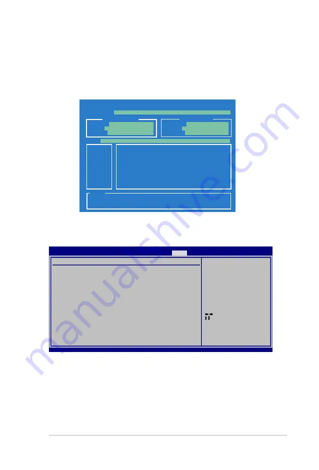
2.7.1 

ASUS EZ Flash 2

Allows you to run ASUS EZ Flash 2. When you press <Enter>, a confirmation 

message appears. Use the left/right arrow key to select between [Yes] or [No], 

then press <Enter> to confirm your choice. Please see page 2-3, section 2.1.2 for 

details.

ASUSTek EZ Flash 2 BIOS ROM Utility V3.00

Current ROM

Update ROM

A:

Note

  [Enter] Select or Load       [B] Backup   [ESC] Exit

  [Tab] Switch                 [Up/Down/Home/End] Move

FLASH TYPE: 

Winbond W39V080A/BP

PATH: 

A:\


BOARD: 

M2A-MVP

VER: 

0204

DATE: 

10/25/06

BOARD: 

Unknown

VER: 

Unknown

DATE: 

Unknown

Save to Profile 1/2

Allows you to save the current BIOS file to the BIOS Flash. Press <Enter> to save 

the file.

Load from Profile 1/2

Allows you to load the previous BIOS settings saved in the BIOS Flash. Press 

<Enter> to load the file.

2.7.2 

ASUS O.C. Profile

O.C. PROFILE Configuration

O.C. Profile 1 Status: Not Installed

O.C. Profile 2 Status: Not Installed

Save to Profile 1

Load from Profile 1

Save to Profile 2

Load from Profile 2

Start O.C. Profile

Save to Profile 1

BIOS SETUP UTILITY


Tools

   Select Screen

    Select Item

+-

   Change Field

Tab   Select Field

F1    General Help

F10   Save and Exit

ESC   Exit

Summary of Contents for M2A-MVP - Motherboard - ATX

Page 1: ...Motherboard M2A MVP ...

Page 2: ...MERCHANTABILITY OR FITNESS FOR A PARTICULAR PURPOSE IN NO EVENT SHALL ASUS ITS DIRECTORS OFFICERS EMPLOYEES OR AGENTS BE LIABLE FOR ANY INDIRECT SPECIAL INCIDENTAL OR CONSEQUENTIAL DAMAGES INCLUDING DAMAGES FOR LOSS OF PROFITS LOSS OF BUSINESS LOSS OF USE OR DATA INTERRUPTION OF BUSINESS AND THE LIKE EVEN IF ASUS HAS BEEN ADVISED OF THE POSSIBILITY OF SUCH DAMAGES ARISING FROM ANY DEFECT OR ERROR ...

Page 3: ...tral Processing Unit CPU 1 9 1 6 1 Installing the CPU 1 9 1 6 2 Installing the CPU heatsink and fan 1 11 1 7 System memory 1 14 1 7 1 Overview 1 14 1 7 2 Memory configurations 1 15 1 7 3 Installing a DIMM 1 19 1 7 4 Removing a DIMM 1 19 1 8 Expansion slots 1 20 1 8 1 Installing an expansion card 1 20 1 8 2 Configuring an expansion card 1 20 1 8 3 Interrupt assignments 1 21 1 8 4 Two PCI slots 1 22...

Page 4: ... 13 2 2 6 Configuration fields 2 13 2 2 7 Pop up window 2 13 2 2 8 Scroll bar 2 13 2 2 9 General help 2 13 2 3 Main menu 2 14 2 3 1 System Time 2 14 2 3 2 System Date 2 14 2 3 3 Legacy Diskette A 2 14 2 3 4 Primary IDE Master Slave SATA1 4 2 15 2 3 5 Storage Configuration 2 16 2 3 6 System Information 2 17 2 4 Advanced menu 2 18 2 4 1 Jumperfree Configuration 2 18 2 4 2 CPU Configuration 2 20 2 4 ...

Page 5: ...S EZ Flash 2 2 37 2 7 2 ASUS O C Profile 2 37 2 8 Exit menu 2 39 2 9 RAID configurations 2 40 2 9 1 Installing hard disks 2 41 2 9 2 ULI RAID configurations 2 41 2 10 Creating a RAID driver disk 2 49 Chapter 3 Software support 3 1 Installing an operating system 3 2 3 2 Support CD information 3 2 3 2 1 Running the support CD 3 2 3 2 2 Drivers menu 3 3 3 2 3 Utilities menu 3 4 3 2 4 Make disk menu 3...

Page 6: ...ause harmful interference to radio or television reception which can be determined by turning the equipment off and on the user is encouraged to try to correct the interference by one or more of the following measures Reorient or relocate the receiving antenna Increase the separation between the equipment and receiver Connect the equipment to an outlet on a circuit different from that to which the...

Page 7: ...al power company If the power supply is broken do not try to fix it by yourself Contact a qualified service technician or your retailer Operation safety Before installing the motherboard and adding devices on it carefully read all the manuals that came with the package Before using the product make sure all cables are correctly connected and the power cables are not damaged If you detect any damag...

Page 8: ...pter tells how to change system settings through the BIOS Setup menus Detailed descriptions of the BIOS parameters are also provided Chapter 3 Software support This chapter describes the contents of the support CD that comes with the motherboard package Where to find more information Refer to the following sources for additional information and for product and software updates 1 ASUS websites The ...

Page 9: ...2 Key3 If you must press two or more keys simultaneously the key names are linked with a plus sign Example Ctrl Alt D Command Means that you must type the command exactly as shown then supply the required item or value enclosed in brackets Example At the DOS prompt type the command line afudos i filename afudos iM2A MVP ROM DANGER WARNING Information to prevent injury to yourself when trying to co...

Page 10: ...aphics card 2 x PCI Express x1 slots 2 x PCI slots CrossFire Supports ATI CrossFire graphics cards both x8 mode Storage RAID AMD SB600 Southbridge supports 1 x IDE connector for two Ultra DMA 133 100 66 33 hard disks 4 x Serial ATA 3 0 Gb s hard disks with RAID 0 1 and 0 1 configuraiton Audio Realtek High Definition Audio with 6 channel CODEC Coaxial S PDIF Out port on the rear panel LAN Marvell 8...

Page 11: ...PU fan connector 1 x Chassis fan connector 1 x Power fan connector 1 x IEEE1394a connector 1 x S PDIF Out connector Front panel High Definition audio connector Chassis intrusion connector CD audio in connector 24 pin ATX Power connector 4 pin ATX 12 V Power connector System panel connector BIOS features 8 Mb Flash ROM AMI BIOS PnP DMI2 0 WfM2 0 Manageability WfM 2 0 DMI 2 0 WOL by PME WOR by PME a...

Page 12: ...xii ...

Page 13: ...1 Product introduction This chapter describes the motherboard features and the new technologies it supports ...

Page 14: ...33 100 66 cable 1 x Floppy disk drive signal cable Accessories I O shield 1 x MVP Switch card Application CD ASUS motherboard support CD Documentation User guide 1 3 Special features 1 3 1 Product highlights Latest processor technology The motherboard supports AMD socket AM2 single core Athlon 64 Sempron and dual core Athlon 64 X2 Athlon 64 FX processors with 2MB 1MB 512KB L2 cache which is based ...

Page 15: ... exceptional high bandwidth See page 1 21 for details Serial ATA 3 0 Gb s technology This motherboard supports the next generation hard drives based on the Serial ATA SATA 3Gb s storage specification The onboard NVIDIA nForce 430 MCP southbridge allows RAID 0 RAID 1 RAID 0 1 RAID 5 and JBOD configurations for four SATA connectors See page 1 28 for details 6 channel High Definition Audio The onboar...

Page 16: ...udio without converting to analog format and keeps the best signal quality See page 1 30 for details USB 2 0 technology The motherboard implements the Universal Serial Bus USB 2 0 specification dramatically increasing the connection speed from the 12 Mbps bandwidth on USB 1 1 to a fast 480 Mbps on USB 2 0 USB 2 0 is backward compatible with USB 1 1 See page 1 26 and 1 31 for details Green ASUS Thi...

Page 17: ...gs can be stored in the CMOS or a separate file giving users freedom to share and distribute their favorite settings See page 2 37 for details ASUS Q Fan2 The ASUS Q Fan 2 technology intelligently adjusts both CPU fan and chassis fan speed according to system loading to ensure quiet cool and efficient operation See page 2 32 for details ASUS MyLogo ASUS My Logo is the new feature present in the mo...

Page 18: ...nt place it on a grounded antistatic pad or in the bag that came with the component Before you install or remove any component ensure that the ATX power supply is switched off or the power cord is detached from the power supply Failure to do so may cause severe damage to the motherboard peripherals and or components Onboard LED The motherboard comes with a standby power LED that lights up to indic...

Page 19: ...ry and damage motherboard components Do not overtighten the screws Doing so can damage the motherboard 1 5 1 Placement direction When installing the motherboard make sure that you place it into the chassis in the correct orientation The edge with external ports goes to the rear part of the chassis as indicated in the image below 1 5 2 Screw holes Place eight 6 screws into the holes indicated by ci...

Page 20: ... 88E8001 ALC660 Socket AM2 PRI_IDE AMD 480X PCI2 PCIEX16_1 SATA3 CHASSIS SATA4 SATA1 SATA2 CHA_FAN1 Super I O EATXPWR PCIEX1_2 DDR2 DIMM_A1 64 bit 240 pin module DDR2 DIMM_B1 64 bit 240 pin module SB600 F_USB34 LAN1_USB12 Below Mic In Center Line Out Top Line In COM1 PARALLEL PORT CPU_FAN USB78 USB56 IE1394_2 FLOPPY VIA VT6308P USB910 USBPW5 8 USBPW910 USBPW1 4 SPDIF_OUT SPDIF_O1 SB_PWR KBPWR Refe...

Page 21: ...ntral Processing Unit CPU The motherboard comes with a 940 pin AM2 socket designed for the AMD Athlon 64 X2 Athlon 64 Athlon 64FX Sempron processor Socket lever The AM2 socket has a different pinout from the 940 pin socket designed for the AMD Opteron processor Make sure you use a CPU designed for the AM2 socket The CPU fits in only one correct orientation DO NOT force the CPU into the socket to p...

Page 22: ...with a small triangle 4 Carefully insert the CPU into the socket until it fits in place 5 When the CPU is in place push down the socket lever to secure the CPU The lever clicks on the side tab to indicate that it is locked 6 Install a CPU heatsink and fan following the instructions that came with the heatsink package Gold triangle Small triangle ...

Page 23: ...d CPU heatsink and fan assembly should come with installation instructions for the CPU heatsink and the retention mechanism If the instructions in this section do not match the CPU documentation follow the latter The retention module base is already installed on the motherboard upon purchase You do not have to remove the retention module base when installing the CPU or installing other motherboard...

Page 24: ...bracket lock to the retention module base A clicking sound denotes that the retention bracket is in place 4 Push down the retention bracket lock on the retention mechanism to secure the heatsink and fan to the module base Make sure that the fan and heatsink assembly perfectly fits the retention mechanism module base otherwise you cannot snap the retention bracket in place ...

Page 25: ... on the motherboard labeled CPU_FAN Do not forget to connect the CPU fan connector Hardware monitoring errors can occur if you fail to plug this connector This connector is backward compatible with the legacy 3 pin CPU fan M2A MVP M2A MVP CPU fan connector CPU_FAN GND CPU FAN PWR CPU FAN IN CPU FAN PWM CPU_FAN ...

Page 26: ...mpared to the 184 pin DDR DIMM DDR2 DIMMs are notched differently to prevent installation on a DDR DIMM socket The figure illustrates the location of the DDR2 DIMM sockets M2A MVP M2A MVP 240 pin DDR2 DIMM sockets DIMM_B1 DIMM_A1 DIMM_B2 DIMM_A2 Channel Sockets Channel A DIMM_A1 and DIMM_A2 Channel B DIMM_B1 and DIMM_B2 In dual channel configurations installing identical the same type and size DDR...

Page 27: ...IMM_A2 DIMM_B2 Always install DIMMs with the same CAS latency For optimum compatibility we recommend that you obtain memory modules from the same vendor Refer to the DDR2 Qualified Vendors List below for details Due to chipset resource allocation the system may detect less than 8 GB system memory when you installed four 2 GB DDR2 memory modules Recommended memory configurations Use only identical ...

Page 28: ...51083QC DS M378T2953CZ3 CE7 512MB Hynix HY5PS12821BFP S5 SS HYMP564U64BP8 S5 1024MB Hynix HY5PS12821BFP S5 DS HYMP512U64BP8 S5 512MB MICRON 5JAIIZ9DQQ SS MT8HTF6464AY 80EA3 1024MB MICRON 5JAIIZ9DQQ DS MT16HTF12864AY 80EA3 512MB MICRON 5ZD22D9GKX SS MT8HTF6464AY 80ED4 1024MB MICRON 5ZD22D9GKX DS MT16HTF12864AY 80ED4 512MB MICRON 6CD22D9GKX SS MT8HTF6464AY 80ED4 1024MB MICRON 6CD22D9GKX DS MT16HTF12...

Page 29: ...ynix HY5PS12821AFP Y5 SS HYMP564U64AP8 Y5 1024MB Hynix HY5PS1G831FP Y5 ECC SS HYMP112U72P8 Y5 512MB Hynix HY5PS12821AFP Y5 ECC SS HYMP564U72AP8 Y5 1024MB Hynix HY5PS12821AFP Y5 ECC DS HYMP512U72AP8 Y5 512MB Hynix HY5PS12821AFP Y4 SS HYMP564U64AP8 Y4 512MB Hynix HY5PS12821AFP Y4 ECC SS HYMP564U72AP8 Y4 256MB CORSAIR MIII00605 SS VS256MB667D2 512MB CORSAIR 64M8CFEG SS VS512MB667D2 1024MB CORSAIR 64M...

Page 30: ...3QC DS M378T2953CZ3 CD5 512MB Hynix HY5PS12821F C4 SS HYMP564U648 C4 1024MB Hynix HY5PS12821F C4 DS HYMP512U648 C4 1024MB Hynix HY5PS12821F C4 ECC DS HYMP512U728 C4 512MB Hynix HY5PS12821FP C4 ECC SS HYMP564U728 C4 512MB Hynix HY5PS12821AFP C3 SS HYMP564U64AP8 C3 1024MB Hynix HY5PS12821AFP C3 DS HYMP512U64AP8 C3 1024MB CORSAIR 64M8CEDG DS VS1GB533D2 512MB ELPIDA E5108AB 5C E SS EBE51UD8ABFA 5C E 5...

Page 31: ...ing clips snap back in place and the DIMM is properly seated 1 7 4 Removing a DIMM To remove a DIMM 1 Simultaneously press the retaining clips outward to unlock the DIMM 2 Remove the DIMM from the socket A DDR2 DIMM is keyed with a notch so that it fits in only one direction Do not force a DIMM into a socket to avoid damaging the DIMM The DDR2 DIMM sockets do not support DDR DIMMs Do not install D...

Page 32: ...Secure the card to the chassis with the screw you removed earlier 6 Replace the system cover 1 8 2 Configuring an expansion card After installing the expansion card configure it by adjusting the software settings 1 Turn on the system and change the necessary BIOS settings if any See Chapter 2 for information on BIOS setup 2 Assign an IRQ to the card Refer to the tables on the next page 3 Install t...

Page 33: ...ng 11 6 IRQ holder for PCI steering 12 7 PS 2 Compatible Mouse Port 13 8 Numeric Data Processor 14 9 Primary IDE SATA Channel 15 10 Secondary IDE SATA Channel A B C D E F G H PCI Slot 1 shared shared shared shared PCI Slot 2 shared shared shared shared IEEE 1394a shared LAN 88E8001 shared PCI E x1_1 shared shared shared shared PCI E x1_2 shared shared shared shared PCI E x16_1 shared shared shared...

Page 34: ...x1 slot This motherboard supports two PCI Express x1 network cards SCSI cards and other cards that comply with the PCI Express specifications The following figure shows a network card installed on the PCI Express x1 slot 1 8 6 Two PCI Express x16 slot This motherboard supports two ATI CrossFire PCI Express x16 graphics cards that comply with the PCI Express specifications The figure shows two grap...

Page 35: ...the table below the system may have a failed or delayed power on self test POST Refer to the table below for possible PCI Express Card configurations Install the MVP Switch Card on the black PCI Express slot Remove it only when you want to install other devices Install two ATI graphics cards from the same GPU family PCI Express x16 slot configurations PCIE x 16_1 blue slot PCIE x 16_2 black slot C...

Page 36: ...4 Reinstall the battery 5 Plug the power cord and turn ON the computer 6 Hold down the Del key during the boot process and enter BIOS setup to re enter data You do not need to clear the RTC when the system hangs due to overclocking For system failure due to overclocking use the C P R CPU Parameter Recall feature Shut down and reboot the system so the BIOS can automatically reset parameter settings...

Page 37: ... up the computer from S1 sleep mode CPU stopped DRAM refreshed system running in low power mode using the connected USB devices Set to 5VSB to wake up from S3 and S4 sleep modes The USBPW1 4 jumpers are for the rear USB ports The USBPW5 8 and USBPW910 jumpers are for the internal USB connectors that you can connect to additional USB ports The USB device wake up feature requires a power supply that...

Page 38: ...table below for the LAN port LED indications Activity Link Speed LED Status Description Status Description OFF No link OFF 10 Mbps connection ORANGE Linked ORANGE 100 Mbps connection BLINKING Data activity GREEN 1 Gbps connection LAN port LED indications SPEED LED ACT LINK LED LAN port 5 Coaxial S PDIF Out port This port connects an external audio output device via a coaxial S PDIF cable 6 Line In...

Page 39: ...ort This 9 pin COM1 port is for pointing devices or other serial devices 12 PS 2 keyboard port purple This port is for a PS 2 keyboard Audio 2 4 or 6 channel configuration Port Headset 2 channel 4 channel 6 channel Light Blue Line In Rear Speaker Out Rear Speaker Out Lime Line Out Front Speaker Out Front Speaker Out Pink Mic In Mic In Bass Center Refer to the audio configuration table below for th...

Page 40: ...e floppy ribbon cable to PIN 1 FLOPPY PIN 1 2 IDE connector 40 1 pin PRI_IDE The onboard IDE connector is for the Ultra DMA 133 100 66 signal cable There are three connectors on each Ultra DMA 133 100 66 signal cable blue black and gray Connect the blue connector to the motherboard s IDE connector then select one of the following modes to configure your device Pin 20 on the IDE connector is remove...

Page 41: ...ATA_RXN4 GND GND RSATA_TXP3 RSATA_TXN3 GND RSATA_RXP3 RSATA_RXN3 GND GND RSATA_TXP2 RSATA_TXN2 GND RSATA_RXP2 RSATA_RXN2 GND GND RSATA_TXP1 RSATA_TXN1 GND RSATA_RXP1 RSATA_RXN1 GND SATA3 SATA4 Enable the Serial ATA Controller and Onboard SATA Boot ROM items in the BIOS if you want to use the Serial ATA RAID feature See section 2 3 5 Storage Configuration for details M2A MVP M2A MVP SATA connectors...

Page 42: ... a chassis intrusion event By default the pins labeled Chassis Signal and Ground are shorted with a jumper cap Remove the jumper caps only when you intend to use the chassis intrusion detection feature M2A MVP M2A MVP Chassis intrusion connector CHASSIS 5VSB_MB Chassis Signal GND Default Plug your Serial ATA boot disk on the master port SATA1 2 to support S3 function Install the Windows 2000 Servi...

Page 43: ...ay damage the motherboard components These are not jumpers Do not place jumper caps on the fan connectors Only the CPU FAN and CHA FAN1 connectors support the ASUS Q Fan 2 feature M2A MVP M2A MVP Fan connectors CPU_FAN GND CPU FAN PWR CPU FAN IN CPU FAN PWM CHA_FAN1 GND Rotation 12V PWR_FAN GND Rotation 12V CPU_FAN CHA_FAN1 PWR_FAN 6 Digital Audio connector 4 1 pin SPDIF_OUT This connector is for ...

Page 44: ...rs USB56 NC GND USB_P6 USB_P6 USB 5V GND USB_P5 USB_P5 USB 5V 1 USB78 NC GND USB_P8 USB_P8 USB 5V GND USB_P7 USB_P7 USB 5V 1 USB910 NC GND USB_P10 USB_P10 USB 5V GND USB_P9 USB_P9 USB 5V 1 The USB 2 0 module is purchased separately 8 IEEE 1394a port connector 10 1 pin IE1394_2 This connector is for a IEEE 1394a port Connect the IEEE 1394a module cable to this connector then install the module to a...

Page 45: ...ct a AC 97 front panel audio module to this connector set the Front Panel Support Type item in the BIOS setup to AC97 See section 2 4 4 Onboard Device Configuration for details M2A MVP M2A MVP Analog front panel connector AAFP Legacy AC 97 compliant definition Azalia compliant definition SENSE2_RETUR PORT1 L PORT2 R PORT2 L SENSE1_RETUR SENSE_SEND PORT1 R PRESENCE GND NC MIC_L Line out_R Line out_...

Page 46: ...Ground Ground Ground PSON Ground 5 Volts 12 Volts 3 Volts 5 Volts Ground 12V DC GND 12V DC GND For a fully configured system we recommend that you use a power supply unit PSU that complies with ATX 12 V Specification 2 0 or later version and provides a minimum power of 400 W Do not forget to connect the 4 pin ATX 12 V power plug otherwise the system will not boot up Use of a PSU with a higher powe...

Page 47: ... The speaker allows you to hear system beeps and warnings ATX power button soft off button 2 pin PWRSW This connector is for the system power button Pressing the power button turns the system on or puts the system in sleep or soft off mode depending on the BIOS settings Pressing the power switch for more than four seconds while the system is ON turns the system OFF Reset button 2 pin RESET This 2 ...

Page 48: ...1 36 Chapter 1 Product introduction ...

Page 49: ...2 BIOS setup This chapter tells how to change the system settings through the BIOS Setup menus Detailed descriptions of the BIOS parameters are also provided ...

Page 50: ...ype format A S then press Enter Windows XP environment a Insert a 1 44 MB floppy disk to the floppy disk drive b Click Start from the Windows desktop then select My Computer c Select the 3 1 2 Floppy Drive icon d Click File from the menu then select Format A Format 3 1 2 Floppy Disk window appears e Select Create an MS DOS startup disk from the format options field then click Start Windows 2000 en...

Page 51: ...o to the Tools menu to select EZ Flash2 and press Enter to enable it You can switch between drives by pressing Tab before the correct file is found Then press Enter 1 Insert the floppy disk USB flash disk that contains the BIOS file to the floppy disk drive or the USB port Press Alt F2 during POST to display the following This function can support devices such as USB flash disk or floppy disk with...

Page 52: ...board support CD to the bootable floppy disk you created earlier 2 Boot the system in DOS mode then at the prompt type afudos o filename where the filename is any user assigned filename not more than eight alphanumeric characters for the main filename and three alphanumeric characters for the extension name A afudos oOLDBIOS1 rom Make sure that the floppy disk is not write protected and has at lea...

Page 53: ...after the BIOS update process is completed Reboot the system from the hard disk drive A afudos iM2AMVP ROM AMI Firmware Update Utility Version 1 19 ASUS V2 07 03 11 24BB Copyright C 2002 American Megatrends Inc All rights reserved WARNING Do not turn off power during flash BIOS Reading file done Reading flash done Advance Check Erasing flash done Writing flash done Verifying flash done Please rest...

Page 54: ...ecksum Starting BIOS recovery Checking for floppy 4 Restart the system after the utility completes the updating process Bad BIOS checksum Starting BIOS recovery Checking for floppy Floppy found Reading file M2AMVP ROM Completed Start flashing When found the utility reads the BIOS file and starts flashing the corrupted BIOS file Prepare the motherboard support CD the USB flash disk or the floppy di...

Page 55: ...l drive for the original or updated BIOS file The utility then updates the corrupted BIOS file Bad BIOS checksum Starting BIOS recovery Checking for floppy 4 Restart the system after the utility completes the updating process Recovering the BIOS from the USB flash disk To recover the BIOS from the USB flash disk 1 Insert the USB flash disk that contains BIOS file to the USB port 2 Turn on the syst...

Page 56: ...IOS file Download the latest BIOS file from the Internet Update the BIOS from an updated BIOS file Update the BIOS directly from the Internet and View the BIOS version information This utility is available in the support CD that comes with the motherboard package ASUS Update requires an Internet connection either through a network or an Internet Service Provider ISP Quit all Windows applications b...

Page 57: ...Updating the BIOS through the Internet To update the BIOS through the Internet 1 Launch the ASUS Update utility from the Windows desktop by clicking Start Programs ASUS ASUSUpdate ASUSUpdate The ASUS Update main window appears 2 Select Update BIOS from the Internet option from the drop down menu then click Next ...

Page 58: ...date BIOS from a file option from the drop down menu then click Next 4 From the FTP site select the BIOS version that you wish to download Click Next 5 Follow the screen instructions to complete the update process The ASUS Update utility is capable of updating itself through the Internet Always update the utility to avail all its features 3 Locate the BIOS file from the Open window then click Open...

Page 59: ...an enable the security password feature or change the power management settings This requires you to reconfigure your system using the BIOS Setup program so that the computer can recognize these changes and record them in the CMOS RAM of the SPI chip The firmware chip on the motherboard stores the Setup utility When you start up the computer the system provides you with the opportunity to run this...

Page 60: ...to another 2 2 3 Navigation keys At the bottom right corner of a menu screen are the navigation keys for that particular menu Use the navigation keys to select items in the menu and change the settings Select Screen Select Item Change Field Tab Select Field F1 General Help F10 Save and Exit ESC Exit v02 58 C Copyright 1985 2006 American Megatrends Inc BIOS SETUP UTILITY Main Advanced Power Boot To...

Page 61: ...ge the value of a field select it then press Enter to display a list of options Refer to 2 2 7 Pop up window 2 2 7 Pop up window Select a menu item then press Enter to display a pop up window with the configuration options for that item 2 2 8 Scroll bar A scroll bar appears on the right side of a menu screen when there are items that do not fit on the screen Press the Up Down arrow keys or Page Up...

Page 62: ... 2 1 BIOS menu screen for information on the menu screen items and how to navigate through them v02 58 C Copyright 1985 2006 American Megatrends Inc Select Screen Select Item Change Field Tab Select Field F1 General Help F10 Save and Exit ESC Exit BIOS SETUP UTILITY Main Advanced Power Boot Tools Exit Use ENTER TAB or SHIFT TAB to select a field Use or to configure system Time System Time 17 20 30...

Page 63: ...movable Media Device if your device is either a ZIP LS 120 or MO drive Configuration options Not Installed Auto CDROM ARMD LBA Large Mode Auto Enables or disables the LBA mode Setting to Auto enables the LBA mode if the device supports this mode and if the device was not previously formatted with LBA mode disabled Configuration options Disabled Auto Block Multi Sector Transfer M Auto Enables or di...

Page 64: ...isabled Enabled 2 3 5 Storage Configuration The items in this menu allow you to set or change the configurations for the IDE devices installed in the system Select an item then press Enter if you wish to configure the item Onchip SATA Channel Enabled Allows you to enable or disable the onchip SATA channel Configuration options Disabled Enabled The succeeding item appears only if the OnChip SATA Ch...

Page 65: ...he items in this menu AMI BIOS Displays the auto detected BIOS information Processor Displays the auto detected CPU specification System Memory Displays the auto detected system memory AMIBIOS Version 0111 Build Date 10 25 06 Processor Type AMD Sempron tm Processor 3000 Speed 1689MHz Count 1 System Memory Installed Size 256MB Usable Size 256MB ...

Page 66: ...um Enabled Select the target CPU frequency and the relevant parameters will be auto adjusted Frequencies higher than CPU manufacturer recommends are not guaranteed to be stable If the system becomes unstable return to the default AI Overclocking Auto Allows selection of CPU overclocking options to achieve desired CPU internal frequency Selct either one of the preset overclocking configuration opti...

Page 67: ...configurable CPU ATI NB HT Link Speed Auto Configuration options Auto x1 200 MHz x2 400 MHz x3 600 MHz x4 800 MHz x5 1 GHz DDR Voltage Auto Allows you to set the DDR memory voltage Configuration options Auto 1 80 V 1 90 V 2 00V 2 10 V Setting a very high voltage may damage the component permanently Setting a very low voltage may cause the system to become unstable NB and SB Voltage Auto Configurat...

Page 68: ...ican Megatrends Inc BIOS SETUP UTILITY Advanced Enable disable the generation of ACPI_PPC _PSS and _PCT objects Cool n Quiet Disabled Enables or disables the Cool n Quiet technology feature Configuration options Disabled Enabled AMD Live Disabled Enables or disables the AMD Live technology feature Configuration options Disabled Enabled Memory Controller Memory Controller Memory Configuration ECC C...

Page 69: ...f Manual the DRAM specified will be programmed regardless Memory Frequency Auto Allows you to select the DRAM Frequency programming method Configuration options Auto Limit Manual The following item appears when the Memory Frequency item is set to Limit and Manual Frequency 200 MHz Allows you to set the memory frequency Configuration options 200 MHz 266 MHz 333 MHz 400 MHz CAS Latency CL Auto Confi...

Page 70: ...e Disabled DRAM SCRUB REDIRECT Disabled DRAM BG Scrub Disabled L2 Cache BG Scrub Disabled Data Cache BG Scrub Disabled BIOS SETUP UTILITY Advanced Select the DRAM Frequency programming method If Auto the DRAM speed will be based on SPDs If Limit the DRAM speed will not exceed the specified value If Manual the DRAM specified will be programmed regardless DRAM ECC Enable Enabled Allows you to enable...

Page 71: ...ns 160ns 320ns 640ns 1 28us 2 56us 5 12us 10 2us 20 5 us 41 0us 81 9us 163 8us 327 7us 655 4us 1 31ms 2 62ms 5 24ms 10 49ms 20 97ms 42 00ms 84 00ms Power Down Control Auto Allows DIMMs to enter power down mode by deasserting the clock enable signal when DIMMs are not in use Configuration options Auto Disabled Alternate VID Auto Specifies the alternate VID while in low power state Configuration opt...

Page 72: ...nk Width x16 Configuration options x1 x2 x4 x8 x16 PCIE GFX2 Link Width x8 Configuration options x1 x2 x4 x8 P2P Writes Between GFX Ports Enabled Configuration options Disabled Enabled 10 Extra Current for GPP Enabled Configuration options Disabled Enabled 10 Extra Current for SB Enabled Configuration options Disabled Enabled 10 Extra Current for GFX1 Enabled Configuration options Disabled Enabled...

Page 73: ...sable the MAC boot ROM This item appears only when the Onboard LAN item is set to Enabled Configuration options Disabled Enabled Serial Port1 Address 3F8 IRQ4 Allows you to select the Serial Port1 base address Configuration options Disabled 3F8 IRQ4 2F8 IRQ3 3E8 IRQ4 2E8 IRQ3 Parallel Port Address 378 Allows you to select the Parallel Port base addresses Configuration options Disabled 378 278 Para...

Page 74: ...field values can cause the system to malfunction Advanced PCI PnP Settings WARNING Setting wrong values in below sections may cause system to malfunction Plug And Play O S No PCI Latency Timer 64 Allocate IRQ to PCI VGA Yes Palette Snooping Disabled IRQ 3 assigned to PCI Device IRQ 4 assigned to PCI Device IRQ 5 assigned to PCI Device IRQ 7 assigned to PCI Device IRQ 9 assigned to PCI Device IRQ 1...

Page 75: ...ice When set to PCI Device the specific IRQ is free for use of PCI PnP devices When set to Reserved the IRQ is reserved for legacy ISA devices Configuration options PCI Device Reserved v02 53 C Copyright 1985 2005 American Megatrends Inc 2 4 6 USB Configuration The items in this menu allows you to change the USB related features Select an item then press Enter to display the configuration options ...

Page 76: ...detect the presence of USB devices at startup If detected the USB controller legacy mode is enabled If no USB device is detected the legacy USB support is disabled Configuration options Disabled Enabled Auto USB 2 0 Controller Mode HiSpeed Allows you to configure the USB 2 0 controller in HiSpeed 480 Mbps or Full Speed 12 Mbps Configuration options FullSpeed HiSpeed BIOS EHCI Hand Off Enabled Allo...

Page 77: ...ion options No Yes 2 5 3 ACPI Version Features ACPI v1 0 Allows you to add more tables for Advanced Configuration and Power Interface ACPI 2 0 specifications Configuration options ACPI v1 0 ACPI v2 0 ACPI v3 0 2 5 4 ACPI APIC support Enabled Allows you to enable or disable the Advanced Configuration and Power Interface ACPI support in the Application Specific Integrated Circuit ASIC When set to En...

Page 78: ... PS 2 Mouse Disabled When set to Enabled this parameter allows you to use the PS 2 mouse to turn on the system This feature requires an ATX power supply that provides at least 1A on the 5VSB lead Configuration options Disabled Enabled Power On By External Modems Disabled This allows either settings of Enabled or Disabled for powering up the computer when the external modem receives a call while th...

Page 79: ...e chasis fan speed in rotations per minute RPM If the fan is not connected to the motherboard the field shows N A Hardware Monitor CPU Temperature 27ºC 80ºF MB Temperature 32ºC 89 5ºF CPU Fan Speed 2812RPM Chasis Fan Speed N A Power Fan Speed N A VCORE Voltage 1 344V 3 3V Voltage 2 784V 5V Voltage 4 327V 12V Voltage 10 761V Smart Q Fan Function Disabled CPU Temperature RTC Resume Disabled Enables ...

Page 80: ...ut through the onboard voltage regulators Select Ignored if you do not wish to display these items Smart Q FAN Function Disabled Allows you to enable or disable the ASUS Q Fan feature that smartly adjusts the fan speeds for more efficient system operation Configuration options Disabled Enabled The following items appear when the Smart Q FAN Function item is set to Enabled CPU Fan type DC Allows yo...

Page 81: ...oot device 1st xxth Boot Device xxx Drive These items specify the boot device priority sequence from the available devices The number of device items that appears on the screen depends on the number of devices installed in the system Configuration options xxx Drive Disabled 2 6 2 Boot Settings Configuration BIOS SETUP UTILITY Boot Allows BIOS to skip certain tests while booting This will decrease ...

Page 82: ...nabled the system waits for the F1 key to be pressed when error occurs Configuration options Disabled Enabled Hit DEL Message Display Enabled When set to Enabled the system displays the message Press DEL to run Setup during POST Configuration options Disabled Enabled Interrupt 19 Capture Disabled When set to Enabled this function allows the option ROMs to trap Interrupt 19 Configuration options Di...

Page 83: ...a user password To clear the supervisor password select the Change Supervisor Password then press Enter The message Password Uninstalled appears After you have set a supervisor password the other items appear to allow you to change other security settings 4 6 1 Boot Device Priority BIOS SETUP UTILITY Boot Security Settings Supervisor Password Not Installed User Password Not Installed Change Superv...

Page 84: ...after you set your password successfully To change the user password follow the same steps as in setting a user password Clear User Password Select this item to clear the user password Password Check Setup When set to Setup BIOS checks for user password when accessing the Setup utility When set to Always BIOS checks for user password both when accessing Setup and booting the system Configuration o...

Page 85: ...RD M2A MVP VER 0204 DATE 10 25 06 BOARD Unknown VER Unknown DATE Unknown Save to Profile 1 2 Allows you to save the current BIOS file to the BIOS Flash Press Enter to save the file Load from Profile 1 2 Allows you to load the previous BIOS settings saved in the BIOS Flash Press Enter to load the file 2 7 2 ASUS O C Profile O C PROFILE Configuration O C Profile 1 Status Not Installed O C Profile 2 ...

Page 86: ...disk or floppy disk with FAT 32 16 format and single partition only DO NOT shutdown or reset the system while updating the BIOS to prevent system boot failure ASUSTek O C Profile Utility V1 00 Current CMOS Restore CMOS A Note Enter Select or Load B Backup ESC Exit Tab Switch Up Down Home End Move PATH A BOARD M2A MVP VER 0111 DATE 10 25 06 BOARD Unknown VER Unknown DATE Unknown ...

Page 87: ...ields other than System Date System Time and Password the BIOS asks for a confirmation before exiting Discard Changes This option allows you to discard the selections you made and restore the previously saved values After selecting this option a confirmation appears Select OK to discard any changes and load the previously saved values Load Setup Defaults This option allows you to load the default ...

Page 88: ...ring combined without parity redundancy data having to be calculated and written With the RAID 0 1 configuration you get all the benefits of both RAID 0 and RAID 1 configurations Use four new hard disk drives or use an existing drive and three new drives for this setup RAID 5 stripes both data and parity information across three or more hard disk drives Among the advantages of RAID 5 configuration...

Page 89: ...s RAID 0 RAID 1 RAID 0 1 RAID 5 and JBOD configurations Use the ULI RAID BIOS Setup utility to configure a disk array Entering the ULI RAID BIOS Setup Utility To enter the ULI RAID BIOS setup utility 1 Boot up your computer and press Del during POST to enter the BIOS setup 2 In the Main Menu go to Storage Configuration and set the Onboard SATA Boot ROM item to Enabled 3 Press F10 to save the chang...

Page 90: ... box The keys on the legend box allow you to navigate through the setup menu options The following lists the keys in the legend box and their corresponding functions SPACE Select an item Move cursor to the next item Enter Confirms a selected item ESC Exit RAID BIOS Setup Utility c 2005 ULi Electronics Inc www uli com tw Create RAID 0 Striping x2 for Performance Create RAID 1 Mirroring for Reliabil...

Page 91: ...rives will be deleted Y N Press Y to continue or press N to return to the menu 5 Key in a RAID name with a maximum of eight 8 alphanumeric characters then press Enter Do not use special characters or symbols 6 The utility displays the RAID Array settings at the bottom of the screen Drive Model Mode Capacity RAID Array Type Channel 0 Master XXXXXXXXXXX SATA 2 XXXXX MB RAID A 0x2 Channel 1 Master XX...

Page 92: ...er Do not use special characters or symbols 6 The utility prompts the following confirmation message Duplicate Data from M to m Y N Press Y to duplicate data from the source disk M to the target disk m or press N to create a RAID 1 set without duplicating the data 7 If you selected Y the utility will duplicate your data The following progress bar appears 8 The utility displays the RAID Array setti...

Page 93: ...ove the cursor to Create RAID 0 1 Striping Mirroring then press Enter 2 The utility prompts the following warning message Data on first 4 drives will be deleted Y N Press Y to continue or press N to return to the menu 3 Key in a RAID name with a maximum of eight 8 alphanumeric characters then press Enter Do not use special characters or symbols 4 The utility displays the RAID Array settings at the...

Page 94: ... and video editing we recommend a higher array block size for optimum performance Drive Model Mode Capacity RAID Array Type Channel 0 Master XXXXXXXXXXX SATA 2 XXXXX MB RAID A JBOD Channel 1 Master XXXXXXXXXXX XXXXX MB Channel 2 Master XXXXXXXXXXX SATA 2 XXXXX MB RAID A JBOD Channel 3 Master XXXXXXXXXXX SATA 2 XXXXX MB Capacity RAID Type Stripe Size RAID Name RAID Array A XXXXX MB JBOD RAIDJ RAID ...

Page 95: ...RAID drives will be deleted Y N Press Y to continue or press N to return to the menu Pressing Y removes the deleted RAID Array item from the list at the bottom of the screen Deleting All RAID configurations To delete all RAID sets 1 From the ULI RAID BIOS Setup utility menu move the cursor to Delete All RAID Settings Partition then press Enter 2 The utility prompts the following warning message Da...

Page 96: ...2 Use the up or down arrow keys to select a drive then press Space or Enter The striped mark 5 appears before a selected drive 3 Repeat step 2 to select the second and third drives 4 The utility prompts the following warning message Data on RAID drives will be deleted Y N Press Y to continue or press N to return to the menu 5 Key in a RAID name with a maximum of eight 8 alphanumeric characters the...

Page 97: ...e 1 3 _ 7 Press 1 to create a RAID driver disk 8 Insert a formatted floppy disk into the floppy drive then press Enter 9 Follow succeeding screen instructions to complete the process OR 1 Start Windows 2 Place the motherboard support CD into the optical drive 3 When the Drivers menu appears click Make ULi Chipset Driver Disk to create a ULI RAID driver disk 4 Insert a floppy disk into the floppy d...

Page 98: ...2 50 Chapter 2 BIOS setup ...

Page 99: ...ASUS M2A MVP 3 3 Software support This chapter describes the contents of the support CD that comes with the motherboard package ...

Page 100: ...n install to avail all motherboard features 3 2 1 Running the support CD Place the support CD to the optical drive The CD automatically displays the Drivers menu if Autorun is enabled in your computer Motherboard settings and hardware options vary Use the setup procedures presented in this chapter for reference only Refer to your OS documentation for detailed information Make sure that you install...

Page 101: ...ate the devices ASUS InstAll Drivers Installation Wizard Installs the ASUS InstAll Drivers installation wizard ATI Chipset Driver Installs the ATI chipset driver AMD Cool n Quiet Driver Installs the AMD Cool n Quiet driver Marvell Yukon Gigabit Ethernet Driver Installs the Marvell Yukon Gigabit Ethernet driver Realtek Audio Driver Installs the Realtek audio driver ...

Page 102: ...art utility monitors the fan speed CPU temperature and system voltages and alerts you of any detected problems This utility helps you keep your computer in healthy operating condition ASUS Update The ASUS Update utility allows you to update the motherboard BIOS in Windows environment This utility requires an Internet connection either through a network or an Internet Service Provider ISP Adobe Rea...

Page 103: ...er The Microsoft DirectX 9 0c is a multimedia technology that enhances computer graphics and sound DirectX improves the multimedia features of you computer so you can enjoy watching TV and movies capturing videos or playing games in your computer Visit the Microsoft website www microsoft com for updates Anti Virus Utility The anti virus application scans identifies and removes computer viruses Vie...

Page 104: ...he folder of the user manual Most user manual files are in Portable Document Format PDF Download the Adobe Acrobat Reader from www adobe com if you do not have one 3 2 6 ASUS Contact information Click the Contact tab to display the ASUS contact information You can also find this information on the inside front cover of this user guide ...

Page 105: ...mat 3 2 7 Other information The icons on the top right corner of the screen give additional information on the motherboard and the contents of the support CD Click an icon to display the specified information Motherboard Info Displays the general specifications of the motherboard ...

Page 106: ...t Filelist Displays the contents of the support CD and a brief description of each in text format Technical support form Displays the ASUS Technical Support Request Form that you have to fill out when requesting technical support ...

Reviews: