background image

ASUS H81M-E R2.0

1-11

1.6 Headers

1. 

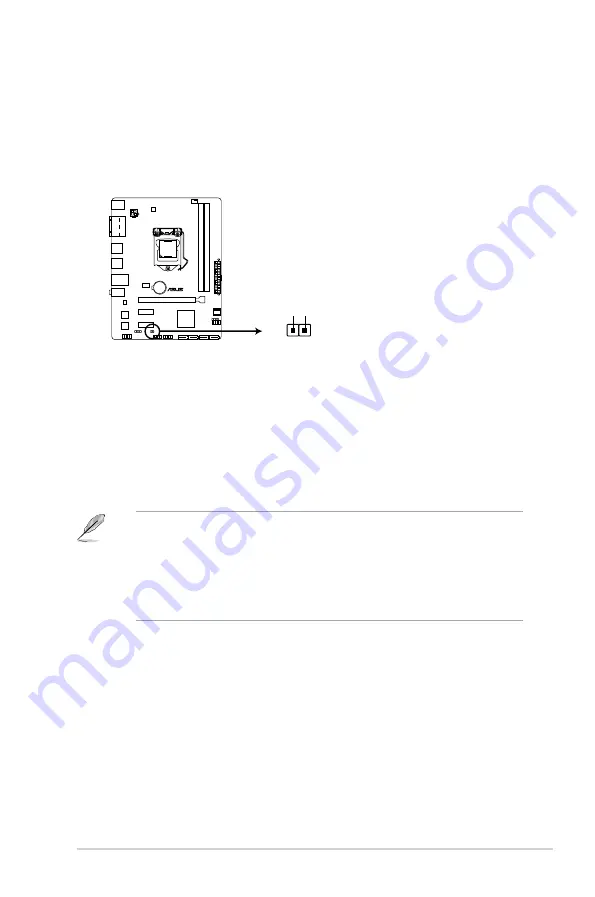
Clear RTC RAM (2-pin CLRTC)

This header allows you to clear the Real Time Clock (RTC) RAM in CMOS. You can 

clear the CMOS memory of date, time, and system setup parameters by erasing the 

CMOS RTC RAM data. The onboard button cell battery powers the RAM data in 

CMOS, which include system setup information such as system passwords.

H81M-E R2.0

H81M-E R2.0 Clear RTC RAM

CLRTC

+3V_BAT GND

PIN 1

To erase the RTC RAM:

1.  Turn OFF the computer and unplug the power cord.

2.  Use a metal object such as a screwdriver to short the two pins.

3.  Plug the power cord and turn ON the computer.

4.  Hold down the <

Del

> key during the boot process and enter BIOS setup to re-

enter data.

• 

If the steps above do not help, remove the onboard battery and short the two pins 

again to clear the CMOS RTC RAM data. After clearing the CMOS, reinstall the 

battery.

• 

You do not need to clear the RTC when the system hangs due to overclocking. For 

system failure due to overclocking, use the CPU Parameter Recall (C.P.R.) feature. 

Shut down and reboot the system, then the BIOS automatically resets parameter 

settings to default values.

Summary of Contents for H81M-E R2.0

Page 1: ...Motherboard H81M E R2 0 ...

Page 2: ...pective companies and are used only for identification or explanation and to the owners benefit without intent to infringe Offer to Provide Source Code of Certain Software This product contains copyrighted software that is licensed under the General Public License GPL under the Lesser General Public License Version LGPL and or other Free Open Source Software Licenses Such software in this product ...

Page 3: ...ssing Unit CPU 1 4 1 4 System memory 1 7 1 5 Expansion slots 1 9 1 6 Headers 1 11 1 7 Connectors 1 12 1 8 Software support 1 19 BIOS information 2 1 Managing and updating your BIOS 2 1 2 2 BIOS setup program 2 6 2 3 Main menu 2 9 2 4 Ai Tweaker menu 2 9 2 5 Advanced menu 2 11 2 6 Monitor menu 2 12 2 7 Boot menu 2 13 2 8 Tools menu 2 14 2 9 Exit menu 2 14 Appendices Notices A 1 ASUS contact informa...

Page 4: ...er Operation safety Before installing the motherboard and adding devices on it carefully read all the manuals that came with the package Before using the product ensure all cables are correctly connected and the power cables are not damaged If you detect any damage contact your dealer immediately To avoid short circuits keep paper clips screws and staples away from connectors slots sockets and cir...

Page 5: ...rly take note of the following symbols used throughout this manual DANGER WARNING Information to prevent injury to yourself when trying to complete a task CAUTION Information to prevent damage to the components when trying to complete a task IMPORTANT Instructions that you MUST follow to complete a task NOTE Tips and additional information to help you complete a task Typography Bold text Indicates...

Page 6: ...n at the maximum transfer rate of DDR3 1600MHz Graphics Integrated Graphics Processor Intel HD Graphics support VGA output support RGB port Supports RGB with max resolution 1920x1200 60Hz Maximum shared memory of 1024MB Expansion slots 1 x PCI Express x16 slot at x16 mode 2 x PCI Express x1 slots Storage Intel H81 Express Chipset 2 x Serial ATA 6 0 Gb s connectors gray 2 x Serial ATA 3 0 Gb s conn...

Page 7: ...B 2 0 1 1 ports 4 ports at mid board 4 ports at the rear panel ASUS unique features ASUS 5X Protection ASUS motherboards safeguard your PC with 5X Protection DIGI VRM DRAM Fuse ESD Guards High Quality 5K Solid Capacitors and Stainless Steel Back I O to ensure the best quality reliability and durability ASUS DIGI VRM ASUS DIGI VRM Digital Power Design for the CPU ASUS 3 Phase Power Design ASUS CPU ...

Page 8: ...ectors 1 x 4 pin CPU Fan connector PWM mode 1 x 4 pin Chassis Fan connector PWM mode 1 x Front panel audio connector 1 x S PDIF Out connector 1 x 24 pin EATX power connector 1 x 4 pin EATX 12V power connector 1 x Speaker connector 1 x System panel connector Operating System Support Windows 8 1 Windows 8 Windows 7 BIOS features 64 Mb Flash ROM UEFI AMI BIOS PnP DMI2 0 WfM2 0 SM BIOS 2 7 ACPI 2 0a M...

Page 9: ... that came with the component Before you install or remove any component ensure that the ATX power supply is switched off or the power cord is detached from the power supply Failure to do so may cause severe damage to the motherboard peripherals or components 1 2 Motherboard overview Before you install the motherboard study the configuration of your chassis to ensure that the motherboard fits into...

Page 10: ...H81M E R2 0 Place this side towards the rear of the chassis 1 2 2 Screw holes Place six screws into the holes indicated by circles to secure the motherboard to the chassis Do not overtighten the screws Doing so can damage the motherboard ...

Page 11: ...USB1112 AAFP ATX12V EATXPWR CPU_FAN CHA_FAN BATTERY Super I O ALC 887 VD2 RTL 8111GR DIGI VRM 22 6cm 8 9in LGA1150 Intel H81 DDR3 DIMM_A1 64bit 240 pin module DDR3 DIMM_B1 64bit 240 pin module SATA6G_1 SATA6G_2 SATA3G_1 SATA3G_2 AUDIO KBMS LAN_USB34 USB3_12 USB56 17 5cm 6 9in VGA COM 64Mb BIOS 1 3 4 2 2 1 7 10 9 11 12 5 6 8 ...

Page 12: ...oard ASUS will process Return Merchandise Authorization RMA requests only if the motherboard comes with the cap on the LGA1150 socket The product warranty does not cover damage to the socket contacts resulting from incorrect CPU installation removal or misplacement loss incorrect removal of the PnP cap Connectors Jumpers Slots LED Page 1 ATX power connectors 24 pin EATXPWR 4 pin ATX12V 1 16 2 CPU ...

Page 13: ...ASUS H81M E R2 0 1 5 1 3 1 Installing the CPU 1 2 3 A B A B C 4 5 ...

Page 14: ...tion 1 3 2 CPU heatsink and fan assembly installation To install the CPU heatsink and fan assembly 2 B A A B 1 Apply the Thermal Interface Material to the CPU heatsink and CPU before you install the heatsink and fan if necessary 3 4 ...

Page 15: ...otched differently from a DDR or DDR2 module DO NOT install a DDR or DDR2 memory module to the DDR3 slot Channel Sockets Channel A DIMM_A1 Channel B DIMM_B1 H81M E R2 0 H81M E R2 0 240 pin DDR3 DIMM sockets DIMM_A1 DIMM_B1 A B B A To uninstall the CPU heatsink and fan assembly 2 1 According to Intel CPU spec DIMM voltage below 1 65V is recommended to protect the CPU ...

Page 16: ...64 bit Windows OS if you want to install 4GB or more on the motherboard This motherboard does not support DIMMs made up of 512 megabits Mb chips or less Memory modules with memory frequency higher than 2133 MHz and its corresponding timing or the loaded X M P Profile is not the JEDEC memory standard The stability and compatibility of these memory modules depend on the CPU s capabilities and other ...

Page 17: ...ll expansion cards The following sub sections describe the slots and the expansion cards that they support Unplug the power cord before adding or removing expansion cards Failure to do so may cause you physical injury and damage motherboard components 2 3 To remove a DIMM B A A ...

Page 18: ...1 Turn on the system and change the necessary BIOS settings if any See Chapter 2 for information on BIOS setup 2 Assign an IRQ to the card 3 Install the software drivers for the expansion card When using PCI cards on shared slots ensure that the drivers support Share IRQ or that the cards do not need IRQ assignments Otherwise conflicts will arise between the two PCI groups making the system unstab...

Page 19: ...computer and unplug the power cord 2 Use a metal object such as a screwdriver to short the two pins 3 Plug the power cord and turn ON the computer 4 Hold down the Del key during the boot process and enter BIOS setup to re enter data If the steps above do not help remove the onboard battery and short the two pins again to clear the CMOS RTC RAM data After clearing the CMOS reinstall the battery You...

Page 20: ...In port light blue This port connects the tape CD DVD player or other audio sources 5 Line Out port lime This port connects a headphone or a speaker In 4 channel 6 channel and 8 channel configurations the function of this port becomes Front Speaker Out 6 Microphone port pink This port connects a microphone To configure an 7 1 channel audio output Use a chassis with HD audio module in the front pan...

Page 21: ...gly recommend that you connect USB 3 0 devices to USB 3 0 ports for faster and better performance from your USB 3 0 devices 9 USB 2 0 ports 5 and 6 These two 4 pin Universal Serial Bus USB ports are for USB 2 0 1 1 devices 10 Serial port This 9 pin COM port is for pointing devices or other serial devices 11 PS 2 keyboard port purple This port is for a PS 2 keyboard Audio 2 1 4 1 5 1 or 7 1 channel...

Page 22: ...e BIOS setup to HD If you want to connect an AC 97 front panel audio module to this connector set the item to AC97 By default this connector is set to HD H81M E R2 0 H81M E R2 0 Front panel audio connector AAFP PIN 1 AGND NC SENSE1_RETUR SENSE2_RETUR PORT1 L PORT1 R PORT2 R SENSE_SEND PORT2 L HD audio compliant pin definition PIN 1 AGND NC NC NC MIC2 MICPWR Line out_R NC Line out_L Legacy AC 97 co...

Page 23: ...U FAN IN CPU FAN PWR GND CHA FAN PWM CHA FAN IN CHA FAN PWR GND CHA_FAN 4 USB 2 0 connectors 10 1 pin USB910 USB1112 These connectors are for USB 2 0 ports Connect the USB module cable to any of these connectors then install the module to a slot opening at the back of the system chassis These USB connectors comply with USB 2 0 specifications and supports up to 480Mbps connection speed Never connec...

Page 24: ...lculator at http support asus com PowerSupplyCalculator PSCalculator aspx SLanguage en us for details 5 ATX power connectors 24 pin EATXPWR 4 pin ATX12V These connectors are for ATX power supply plugs The power supply plugs are designed to fit these connectors in only one orientation Find the proper orientation and push down firmly until the connectors completely fit H81M E R2 0 H81M E R2 0 ATX po...

Page 25: ...rial ATA 3 0 Gb s signal cables 8 Intel H81 Serial ATA 6 0Gb s connectors 7 pin SATA6G_1 2 gray These connectors connect to Serial ATA 6 0 Gb s hard disk drives via Serial ATA 6 0 Gb s signal cables When using hot plug and NCQ set the SATA Mode Selection item in the BIOS to AHCI SATA6G_1 GND RSATA_RXP1 RSATA_RXN1 GND RSATA_TXN1 RSATA_TXP1 GND SATA6G_2 GND RSATA_RXP2 RSATA_RXN2 GND RSATA_TXN2 RSATA...

Page 26: ...D cable to this connector The system power LED lights up when you turn on the system power and blinks when the system is in sleep mode Hard disk drive activity LED 2 pin HDD_LED This 2 pin connector is for the HDD Activity LED Connect the HDD Activity LED cable to this connector The HDD LED lights up or flashes when data is read from or written to the HDD ATX power button soft off button 2 pin PWR...

Page 27: ...The contents of the Support DVD are subject to change at any time without notice Visit the ASUS website at www asus com for updates The following screen is for reference only To run the Support DVD Place the Support DVD into the optical drive If Autorun is enabled in your computer the DVD automatically displays the Specials screen which lists the unique features of your ASUS motherboard Click Driv...

Page 28: ...1 20 Chapter 1 Product introduction ...

Page 29: ...ftwares drivers and the BIOS version easily With this utlity you can also manually update the saved BIOS and select a boot logo when the system goes into POST To launch EZ Update click EZ Update on the AI Suite 3 main menu bar Model Name H81M E R2 0 Version 0306 Release Date 08 08 2014 Click to automatically update your motherboard s driver software and firmware Click to find and select the BIOS f...

Page 30: ...able it 3 Press Tab to switch to the Drive field 4 Press the Up Down arrow keys to find the USB flash disk that contains the latest BIOS and then press Enter 5 Press Tab to switch to the Folder Info field 6 Press the Up Down arrow keys to find the BIOS file and then press Enter to perform the BIOS update process Reboot the system when the update process is done This function supports USB flash dis...

Page 31: ... file When found the utility reads the BIOS file and enters ASUS EZ Flash 2 utility automatically 4 The system requires you to enter BIOS Setup to recover BIOS setting To ensure system compatibility and stability we recommend that you press F5 to load default BIOS values DO NOT shut down or reset the system while updating the BIOS Doing so can cause system boot failure 2 1 4 ASUS BIOS Updater ASUS...

Page 32: ...ect boot device ESC to boot using defaults 4 When the booting message appears press Enter within five 5 seconds to enter FreeDOS prompt Welcome to FreeDOS http www freedos org C d D 5 On the FreeDOS prompt type d then press Enter to switch the disk from Drive C optical drive to Drive D USB flash drive ISOLINUX 3 20 2006 08 26 Copyright C 1994 2005 H Peter Anvin A Bootable DVD CD is detected Press ...

Page 33: ...ct the BIOS file and press Enter 5 Select Yes then press Enter When BIOS update is done press ESC to exit BIOS Updater 6 Restart your computer DO NOT shut down or reset the system while updating the BIOS to prevent system boot failure Ensure to load the BIOS default settings to ensure system compatibility and stability Select the Load Optimized Defaults item under the Exit BIOS menu See Chapter 2 ...

Page 34: ... fails to boot after changing any BIOS setting try to clear the CMOS and reset the motherboard to the default value See section 1 6 Jumpers for information on how to erase the RTC RAM BIOS menu screen The BIOS setup program can be used under two modes EZ Mode and Advanced Mode You can change modes from the Exit menu or from the Exit Advanced Mode button in the EZ Mode Advanced Mode screen 2 2 BIOS...

Page 35: ...imal mode Loads optimized default Selects the boot device priority Selects the boot device priority Displays the system properties of the selected mode on the right hand side Selects the Advanced mode functions Displays the Advanced mode menus EZ Mode By default the EZ Mode screen appears when you enter the BIOS setup program The EZ Mode provides you an overview of the basic system information and...

Page 36: ...tton Last modified settings Quick note Menu bar The menu bar on top of the screen has the following main items My Favorites For saving the frequently used system settings and configuration Main For changing the basic system configuration Ai Tweaker For changing the overclocking settings Advanced For changing the advanced system settings Monitor For displaying the system temperature power status an...

Page 37: ...OS password See section 1 6 Jumpers for information on how to erase the RTC RAM The Administrator or User Password items on top of the screen show the default Not Installed After you set a password these items show Installed 2 4 Ai Tweaker menu The Ai Tweaker menu items allow you to configure overclocking related items Be cautious when changing the settings of the Ai Tweaker menu items Incorrect f...

Page 38: ...2 10 Chapter 2 Getting started Scroll down to display the following items Scroll down to display the following items ...

Page 39: ...vanced menu The Advanced menu items allow you to change the settings for the CPU and other system devices Be cautious when changing the settings of the Advanced menu items Incorrect field values can cause the system to malfunction ...

Page 40: ...2 12 Chapter 2 Getting started 2 6 Monitor menu The Monitor menu displays the system temperature power status and allows you to change the fan settings Scroll down to display the following items ...

Page 41: ...2 13 ASUS H81M E R2 0 2 7 Boot menu The Boot menu items allow you to change the system boot options Scroll down to display the following items ...

Page 42: ...igure options for special functions Select an item then press Enter to display the submenu 2 9 Exit menu The Exit menu items allow you to load the optimal default values for the BIOS items and save or discard your changes to the BIOS items You can access the EZ Mode from the Exit menu ...

Page 43: ...different from that to which the receiver is connected Consult the dealer or an experienced radio TV technician for help The use of shielded cables for connection of the monitor to the graphics card is required to assure compliance with FCC regulations Changes or modifications to this unit not expressly approved by the party responsible for compliance could void the user s authority to operate thi...

Page 44: ...ecycling and takeback programs come from our commitment to the highest standards for protecting our environment We believe in providing solutions for you to be able to responsibly recycle our products batteries other components as well as the packaging materials Please go to http csr asus com english Takeback htm for detailed recycling information in different regions Canadian Department of Commun...

Page 45: ... INTERNATIONAL America Address 800 Corporate Way Fremont CA 94539 USA Telephone 1 510 739 3777 Fax 1 510 608 4555 Web site http www asus com us Technical Support Support fax 1 812 284 0883 General support 1 812 282 2787 Online support http www service asus com ASUS COMPUTER GmbH Germany and Austria Address Harkort Str 21 23 D 40880 Ratingen Germany Fax 49 2102 959931 Web site http www asus com de ...

Page 46: ...E R2 0 conform with the essential requirements of the following directives 2004 108 EC EMC Directive EN 55022 2010 AC 2011 EN 61000 3 2 2006 A2 2009 EN 55013 2001 A1 2003 A2 2006 EN 55024 2010 EN 61000 3 3 2008 EN 55020 2007 A11 2011 1999 5 EC R TTE Directive EN 300 328 V1 7 1 2006 10 EN 300 440 1 V1 6 1 2010 08 EN 300 440 2 V1 4 1 2010 08 EN 301 511 V9 0 2 2003 03 EN 301 908 1 V5 2 1 2011 05 EN 3...

Reviews: