background image

ASUS H170M-E D3

1-7

1.4 

System memory

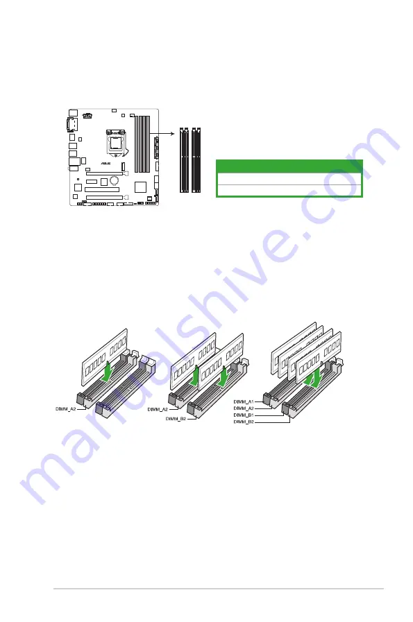
1.4.1 Overview

This motherboard comes with four Double Data Rate 3 (DDR3) Dual Inline Memory Module 

(DIMM) sockets. The figure illustrates the location of the DDR3 DIMM sockets:

1.4.2 

Memory configurations

You may install 1 GB, 2 GB, 4 GB, 8 GB, and 16 GB unbuffered non-ECC DDR3 DIMMs into 

the DIMM sockets. You can refer to the recommended memory population below.

Recommended memory configurations

Channel

Sockets

Channel A

DIMM_A1 & DIMM_A2

Channel B

DIMM_B1 & DIMM_B2

H170M-E D3 240-pin DDR3 DIMM sockets

DIMM_A1 DIMM_A2

DIMM_B1 DIMM_B2

H170M-E D3

Summary of Contents for H170M-E D3

Page 1: ...Motherboard H170M E D3 ...

Page 2: ...spective companies and are used only for identification or explanation and to the owners benefit without intent to infringe Offer to Provide Source Code of Certain Software This product contains copyrighted software that is licensed under the General Public License GPL under the Lesser General Public License Version LGPL and or other Free Open Source Software Licenses Such software in this product...

Page 3: ...System memory 1 7 1 5 Expansion slots 1 10 1 6 Headers 1 12 1 7 Connectors 1 13 1 8 Onboard LED 1 22 1 9 Software support 1 23 Chapter 2 BIOS information 2 1 Managing and updating your BIOS 2 1 2 2 BIOS setup program 2 6 2 3 My Favorites 2 15 2 4 Main menu 2 16 2 5 Ai Tweaker menu 2 18 2 6 Advanced menu 2 26 2 7 Monitor menu 2 35 2 8 Boot menu 2 38 2 9 Tool menu 2 43 2 10 Exit menu 2 44 Appendices...

Page 4: ...erboard and adding components carefully read all the manuals that came with the package Before using the product ensure all cables are correctly connected and the power cables are not damaged If you detect any damage contact your dealer immediately To avoid short circuits keep paper clips screws and staples away from connectors slots sockets and circuitry Avoid dust humidity and temperature extrem...

Page 5: ...ks properly take note of the following symbols used throughout this manual DANGER WARNING Information to prevent injury to yourself when completing a task CAUTION Information to prevent damage to the components when completing a task IMPORTANT Instructions that you MUST follow to complete a task NOTE Tips and additional information to help you complete a task Typography Bold text Indicates a menu ...

Page 6: ... memory architecture Supports Intel Extreme Memory Profile XMP Refer to www asus com for the latest Memory QVL Qualified Vendors List Hyper DIMM support is subject to the physical characteristics of individual CPUs Please refer to Memory QVL Qualified Vendors List for details Expansion slots 1 x PCI Express 3 0 2 0 x16 slot at x16 mode 1 x PCI Express 3 0 2 0 x16 slot max at x4 mode compatible wit...

Page 7: ...Intel Smart Response Technology This function works depending on the type of CPU installed LAN Realtek 8111H Gigabit LAN controller USB Intel H170 Express Chipset supports ASUS USB 3 0 Boost 8 x USB 3 0 2 0 ports 4 ports at mid board 4 ports at the rear panel blue 6 x USB 2 0 1 1 ports 4 ports at mid board 2 ports at the rear panel ASUS unique features Proven Quality ASUS 5X PROTECTION II ASUS LAN...

Page 8: ...nti Surge EZ DIY Push Notice Monitor your PC status with smart devices in real time UEFI BIOS EZ Mode Featuring friendly graphics user interface ASUS CrashFree BIOS 3 ASUS EZ Flash 3 Q Design ASUS Q Slot ASUS Q DIMM ASUS quiet thermal solution Quiet Thermal Design ASUS Fan Xpert 2 Stylish Fanless Design PCH heatsink solution Rear panel I O ports 1 x PS 2 keyboard port purple 1 x PS 2 mouse port gr...

Page 9: ...r 1 x System panel connector 1 x Clear CMOS header BIOS features 128 Mb Flash ROM UEFI AMI BIOS PnP DMI 3 0 WfM2 0 SM BIOS 3 0 ACPI 5 0 Multi language BIOS ASUS EZ Flash 3 ASUS CrashFree BIOS 3 F11 EZ Tuning Wizard F6 Qfan Control F3 My Favorites Quick Note Last Modified Log F12 PrintScreen function and ASUS DRAM SPD Serial Presence Detect memory information Manageability WfM 2 0 DMI 3 0 WOL by PM...

Page 10: ...x ...

Page 11: ...he power supply Failure to do so may cause severe damage to the motherboard peripherals or components 1 2 Motherboard overview Before you install the motherboard study the configuration of your chassis to ensure that the motherboard fits Unplug the power cord before installing or removing the motherboard Failure to do so can cause you physical injury and damage to motherboard components 1 2 1 Plac...

Page 12: ...LC 887 VD2 ASM 1083 KBMS DVI VGA CLRTC TPM 22 4cm 8 8in 24 4cm 9 6in DDR3 DIMM_A1 64bit 240 pin module DDR3 DIMM_A2 64bit 240 pin module DDR3 DIMM_B1 64bit 240 pin module DDR3 DIMM_B2 64bit 240 pin module LAN_USB910 USB3_56 HDMI USB3_78 CHA_FAN2 CPU_FAN CHA_FAN1 LGA1151 DIGI VRM COM SPDIF_OUT EATX12V USB3_34 USB3_12 128Mb BIOS PANEL SB_PWR AUDIO SATA6G_3 SATA6G_4 SATA6G_5 SATA6G_6 Super I O Intel ...

Page 13: ...CPU socket 1 3 4 DDR3 DIMM slots 1 7 5 USB 3 0 connectors 20 1 pin USB3_12 USB3_34 1 16 6 M 2 Socket 3 1 18 7 Intel H170 Serial ATA 6 0 Gb s connector 7 pin SATA6G_3 6 1 20 8 System panel connector 20 5 pin PANEL 1 21 9 Standby Power LED SB_PWR 1 22 10 TPM connector 14 1 pin TPM 1 16 11 Clear RTC RAM 2 pin CLRTC 1 12 12 USB 2 0 connectors 10 1 pin USB1112 USB1314 1 15 13 LPT connector 26 1 pin LPT...

Page 14: ... cap is on the socket and the socket contacts are not bent Contact your retailer immediately if the PnP cap is missing or if you see any damage to the PnP cap socket contacts motherboard components Keep the cap after installing the motherboard ASUS will process Return Merchandise Authorization RMA requests only if the motherboard comes with the cap on the LGA1151 socket The product warranty does n...

Page 15: ...ASUS H170M E D3 1 5 A B C 5 4 1 3 2 CPU heatsink and fan assembly installation Apply the Thermal Interface Material to the CPU heatsink and CPU before you install the heatsink and fan if necessary ...

Page 16: ...1 6 Chapter 1 Product introduction 3 4 A B B A To uninstall the CPU heatsink and fan assembly 2 1 To install the CPU heatsink and fan assembly 2 B A A B 1 ...

Page 17: ...f the DDR3 DIMM sockets 1 4 2 Memory configurations You may install 1 GB 2 GB 4 GB 8 GB and 16 GB unbuffered non ECC DDR3 DIMMs into the DIMM sockets You can refer to the recommended memory population below Recommended memory configurations Channel Sockets Channel A DIMM_A1 DIMM_A2 Channel B DIMM_B1 DIMM_B2 H170M E D3 240 pin DDR3 DIMM sockets DIMM_A1 DIMM_A2 DIMM_B1 DIMM_B2 H170M E D3 ...

Page 18: ...vendor to get the correct memory modules You may install varying memory sizes in Channel A and Channel B The system maps the total size of the lower sized channel for the dual channel configuration Any excess memory from the higher sized channel is then mapped for single channel operation Due to the memory address limitation on 32 bit Windows OS when you install 4GB or more memory on the motherboa...

Page 19: ...ASUS H170M E D3 1 9 1 4 3 Installing a DIMM 1 2 3 To remove a DIMM B A ...

Page 20: ... removed earlier 6 Replace the system cover 1 5 2 Configuring an expansion card After installing the expansion card configure it by adjusting the software settings 1 Turn on the system and change the necessary BIOS settings if any See Chapter 2 for information on BIOS setup 2 Assign an IRQ to the card 3 Install the software drivers for the expansion card When using PCI cards on shared slots ensure...

Page 21: ...ng multiple graphics cards for better thermal environment VGA configuration PCI Express operating mode PCIe 3 0 x16_1 gray PCIe 3 0 x16_2 Single VGA PCIe card x16 Recommended for single VGA card N A Dual VGA PCIe cards x16 x4 IRQ assignments for this motherboard A B C D E F G H PCIEx16_1 shared PCIEx16_2 shared PCIEx1_1 shared PCI 1 shared Realtek 8111H LAN Controller shared USB 2 0 Controller 1 s...

Page 22: ...ct such as a screwdriver to short the two pins 3 Plug the power cord and turn ON the computer 4 Hold down the Del key during the boot process and enter BIOS setup to re enter data If the steps above do not help remove the onboard battery and short the two pins again to clear the CMOS RTC RAM data After clearing the CMOS reinstall the battery You do not need to clear the RTC when the system hangs d...

Page 23: ...the function of the audio ports in 2 1 4 1 5 1 or 7 1 channel configuration 1 PS 2 mouse port green This port is for a PS 2 mouse 2 Video Graphics Adapter VGA port This 15 pin port is for a VGA monitor or other VGA compatible devices 3 LAN RJ 45 port This port allows Gigabit connection to a Local Area Network LAN through a network hub LAN port LED indications LAN port Speed LED Activity Link LED A...

Page 24: ...niversal Serial Bus USB ports are for USB 3 0 devices USB 3 0 devices can only be used for data storage We strongly recommend that you connect USB 3 0 devices to USB 3 0 ports for faster and better performance from your USB 3 0 devices Due to the design of the Intel 100 series chipset all USB devices connected to the USB 2 0 and USB 3 0 ports are controlled by the xHCI controller Some legacy USB d...

Page 25: ...e to any of these connectors then install the module to a slot opening at the back of the system chassis These USB connectors comply with USB 2 0 specifications and supports up to 480Mbps connection speed Never connect a 1394 cable to the USB connectors Doing so will damage the motherboard The USB 2 0 module is purchased separately H170M E D3 Serial port COM connector PIN 1 COM DCD TXD GND RTS RI ...

Page 26: ...ore keys digital certificates passwords and data A TPM system also helps enhance network security protects digital identities and ensures platform integrity The TPM module is purchased separately H170M E D3 USB3 0 Front panel connectors USB3_12 USB3 5V IntA_P1_SSRX IntA_P1_SSRX GND IntA_P1_SSTX IntA_P1_SSTX GND IntA_P1_D IntA_P1_D GND PIN 1 USB3 5V IntA_P2_SSRX IntA_P2_SSRX GND IntA_P2_SSTX IntA_P...

Page 27: ...stem stability 5 ATX power connectors 24 pin EATXPWR 8 pin EATX12V These connectors are for ATX power supply plugs The power supply plugs are designed to fit these connectors in only one orientation Find the proper orientation and push down firmly until the connectors completely fit 6 LPT connector 26 1 pin LPT The LPT Line Printing Terminal connector supports devices such as a printer LPT standar...

Page 28: ...ct an AC 97 front panel audio module to this connector set the item to AC97 By default this connector is set to HD Audio See section 2 6 8 Onboard Devices Configuration for details 8 M 2 socket 3 This socket allows you to install an M 2 NGFF SSD module This socket supports M Key and 2242 2260 2280 storage devices When using Intel Desktop Responsiveness technologies with PCIe M 2 device ensure to s...

Page 29: ... air flow inside the system may damage the motherboard components These are not jumpers Do not place jumper caps on the fan connectors The CPU_FAN connector supports a CPU fan of maximum 1A 12 W fan power Only the 4 pin CPU fan supports the ASUS Fan Xpert 2 feature 10 CPU and chassis fan connectors 4 pin CPU_FAN 4 pin CHA_FAN 1 2 Connect the fan cables to the fan connectors on the motherboard ensu...

Page 30: ...and NCQ set the SATA Mode Selection item in the BIOS to AHCI See section 2 6 6 SATA Configuration for details SATA6G_6 GND RSATA_TXP6 RSATA_TXN6 GND RSATA_RXN6 RSATA_RXP6 GND SATA6G_5 GND RSATA_TXP5 RSATA_TXN5 GND RSATA_RXN5 RSATA_RXP5 GND SATA6G_4 GND RSATA_TXP4 RSATA_TXN4 GND RSATA_RXN4 RSATA_RXP4 GND SATA6G_3 GND RSATA_TXP3 RSATA_TXN3 GND RSATA_RXN3 RSATA_RXP3 GND H170M E D3 Intel SATA 6 0Gb s ...

Page 31: ...ear system beeps and warnings ATX power button soft off button 2 pin PWR_SW This connector is for the system power button Pressing the power button turns the system on or puts the system in sleep or soft off mode depending on the operating system settings Pressing the power switch for more than four seconds while the system is ON turns the system OFF Reset button 2 pin RESET This 2 pin connector i...

Page 32: ...indicate that the system is ON in sleep mode or in soft off mode This is a reminder that you should shut down the system and unplug the power cable before removing or plugging in any motherboard component The illustration below shows the location of the onboard LED H170M E D3 Standby power LED H170M E D3 SB_PWR ON Standby Power Powered Off OFF ...

Page 33: ...stall to avail all motherboard features The contents of the Support DVD are subject to change at any time without notice Visit the ASUS website at www asus com for updates The following screen is for reference only To run the Support DVD Place the Support DVD into the optical drive If Autorun is enabled in your computer the DVD automatically displays the lists of the unique features of your ASUS m...

Page 34: ...1 24 Chapter 1 Product introduction ...

Page 35: ...twares drivers and the BIOS version easily With this utlity you can also manually update the saved BIOS and select a boot logo when the system goes into POST To launch EZ Update click EZ Update on the AI Suite 3 main menu bar BIOS information 2 EZ Update requires an Internet connection either through a network or an ISP Internet Service Provider Click to automatically update your motherboard s dri...

Page 36: ...ia USB or Internet Via USB a Insert the USB flash disk that contains the latest BIOS file to the USB port then select by USB b Press Tab to switch to the Drive field c Press the Up Down arrow keys to find the USB flash disk that contains the latest BIOS and then press Enter d Press Tab to switch to the Folder Info field e Press the Up Down arrow keys to find the BIOS file and then press Enter to p...

Page 37: ...utility reads the BIOS file and enters ASUS EZ Flash 3 utility automatically 4 The system requires you to enter BIOS Setup to recover BIOS settings To ensure system compatibility and stability we recommend that you press F5 to load default BIOS values DO NOT shut down or reset the system while updating the BIOS Doing so can cause system boot failure 2 1 4 ASUS BIOS Updater ASUS BIOS Updater allows...

Page 38: ...UEFI FAT aigo miniking 250MB Enter Setup 4 When the booting message appears press Enter within five 5 seconds to enter FreeDOS prompt Welcome to FreeDOS http www freedos org C d D 5 On the FreeDOS prompt type d then press Enter to switch the disk from Drive C optical drive to Drive D USB flash drive ISOLINUX 3 20 2006 08 26 Copyright C 1994 2005 H Peter Anvin A Bootable DVD CD is detected Press EN...

Page 39: ...file and press Enter 4 After the BIOS Updater checks the selected BIOS file select Yes to confirm the BIOS update Are you sure you want to update the BIOS Yes No The BIOS Backup feature is not supported due to security regulations 5 Select Yes then press Enter When BIOS update is done press ESC to exit BIOS Updater 6 Restart your computer DO NOT shut down or reset the system while updating the BIO...

Page 40: ...mmend you always shut down the system properly from the operating system The BIOS setup screens shown in this section are for reference purposes only and may not exactly match what you see on your screen Visit the ASUS website at www asus com to download the latest BIOS file for this motherboard Ensure that a mouse is connected to your motherboard if you want to use the mouse to control the BIOS s...

Page 41: ...device options vary depending on the devices you installed to the system Saves the changes and resets the system Selects the display language of the BIOS setup program Displays the CPU motherboard temperature CPU voltage output CPU chassis fan speed and SATA information Displays the system properties of the selected mode Click Enter to switch EZ System Tuning modes Displays the Advanced mode menus...

Page 42: ...U motherboard temperature CPU and memory voltage output Quick Note 2 2 2 Advanced Mode The Advanced Mode provides advanced options for experienced end users to configure the BIOS settings The figure below shows an example of the Advanced Mode Refer to the following sections for the detailed configurations To access the EZ Mode click EzMode F7 or press F7 Popup window 2 8 Chapter 2 Getting started ...

Page 43: ...tes for more information Q Fan Control F6 This button above the menu bar displays the current settings of your fans Use this button to manually tweak the fans to your desired settings Refer to section 2 2 3 QFan Control for more information EZ Tuning Wizard F11 This button above the menu bar allows you to change the motherboard s SATA mode from AHCI to RAID mode Refer to section 2 2 4 EZ Tuning Wi...

Page 44: ...ll bar appears on the right side of a menu screen when there are items that do not fit on the screen Press the Up Down arrow keys or Page Up Page Down keys to display the other items on the screen General help At the bottom left corner of the menu screen is a brief description of the selected item Use F12 key to capture the BIOS screen and save it to the removable storage device Configuration fiel...

Page 45: ...e the operating speed of your CPU and chassis fans Click to select a fan to be configured Click to activate PWM Mode Click to undo the changes Click to apply the fan setting Click to go back to main menu Select a profile to apply to your fans Click to activate DC Mode ASUS H170M E D3 2 11 ...

Page 46: ... speed To configure your fans 1 Select the fan that you want to configure and to view its current status 2 Click and drag the speed points to adjust the fans operating speed 3 Click Apply to save the changes then click Exit ESC Speed points Click to manually configure your fans 2 12 Chapter 2 Getting started ...

Page 47: ...RAID To create RAID 1 Press F11 on your keyboard or click from the BIOS screen to open EZ Tuning Wizard screen 2 Click Yes to enable RAID Ensure that your HDDs have no existing RAID volumes Ensure to connect your HDDs to Intel SATA connectors 3 The available HDDs display Click Next to continue ASUS H170M E D3 2 13 ...

Page 48: ...n click Next b For Super Speed select from Super Speed RAID0 or Super Speed RAID5 then click Next You can only select Easy Backup RAID 10 if you connect four 4 HDDs 5 After selecting the type of RAID click Yes to continue the RAID setup 6 After the RAID setup is done click Yes to exit the setup then click OK to reset your system 2 14 Chapter 2 Getting started ...

Page 49: ...lated items by default You can personalize this screen by adding or removing items Adding items to My Favorites To add BIOS items 1 Press F3 on your keyboard or click from the BIOS screen to open Setup Tree Map screen 2 On the Setup Tree Map screen select the BIOS items that you want to save in MyFavorites screen Main menu panel Submenu panel Selected shortcut items ASUS H170M E D3 2 15 ...

Page 50: ...orean 2 4 2 Security The Security menu items allow you to change the system security settings If you have forgotten your BIOS password erase the CMOS Real Time Clock RTC RAM to clear the BIOS password See section 1 6 Headers for information on how to erase the RTC RAM The Administrator or User Password items on top of the screen show the default Not Installed After you set a password these items s...

Page 51: ...assword the Administrator Password item on top of the screen shows Not Installed User Password If you have set a user password you must enter the user password for accessing the system The User Password item on top of the screen shows the default Not Installed After you set a password this item shows Installed To set a user password 1 Select the User Password item and press Enter 2 From the Create...

Page 52: ...Limit Auto Select Auto to apply the CPU default Turbo Ratio setting or manually assign a 2 Core Limit value that must be higher than or equal to the 3 Core Ratio Limit If you assign a value for 2 Core Ratio Limit do not set the 1 Core Ratio Limit to Auto 2 5 Ai Tweaker menu The Ai Tweaker menu items allow you to configure overclocking related items Be cautious when changing the settings of the Ai ...

Page 53: ... to provide better granularity Configuration options Disabled Enabled 2 5 4 DRAM Frequency Auto This item allows you to set the memory operating frequency The configurable options vary with the BCLK base clock frequency setting Select the auto mode to apply the optimized setting Configuration options DDR3 800MHz DDR3 933MHz DDR3 1066MHz DDR3 1200MHz DDR3 1333MHz DDR3 1400MHz DDR3 1500MHz DDR3 1600...

Page 54: ...tage The CPU working voltage will decrease proportionally depending on the CPU loading Higher levels of the load line calibration can get a higher voltage and a better overclocking performance but increases the CPU and VRM thermal Select from level 1 to 7 to adjust the CPU power voltage from 0 to 100 Configuration options Auto Level 1 Level 2 Level 3 Level 4 Level 5 Level 6 Level 7 The boosted per...

Page 55: ...e Power Phase Response Fast This item allows you to set a faster phase response for the CPU to increase system performance or to slower phase response to decrease DRAM power efficiency Configuration options Ultra Fast Fast Medium Regular CPU Graphics Load Line Calibration Auto Load line is defined by Intel VRM specification and affects the GT power voltage The GT working voltage will decrease prop...

Page 56: ...guration options Auto Standard Optimized Extreme Power Phase Response DO NOT remove the thermal module when setting this item to Extreme or Power Phase Response The thermal conditions should be monitored The following item appears only when you set the CPU Power Phase Control to Power Phase Response Power Phase Response Fast This item allows you to set a faster phase response for the CPU to increa...

Page 57: ...Line Auto This item allows you to set the DC loadline defined in 1 100 mOhms Use the and keys to adjust the value Configuration options Auto 0 01 62 49 2 5 11 CPU Core Cache Current Limit Max Auto Allows you to set a higher current limit to prevent a frequency or power throttling when overclocking Use the or keys to adjust the value The values range from 0 00A to 255 50A with a 0 25A interval 2 5 ...

Page 58: ...0 635V to 0 635V with a 0 005V interval 2 5 17 DRAM Voltage Auto This item allows you to set the voltage for the DRAM Use the and keys to adjust the value The values range from 1 000V to 1 800V with a 0 005 interval 2 5 18 CPU System Agent Voltage Auto This item allows you to set the voltage for the CPU System Agent Use the and keys to adjust the value The values range from 0 700V to 1 685V with a...

Page 59: ... 1 15V 2 5 21 DRAM REF Voltage Control DRAM CTRL REF Voltage Auto Allows you to set the DRAM reference voltage on the control lines You can use the or keys to adjust the value The values range from 0 39500V to 0 63000V with a 0 00500V interval DRAM DATA REF Voltage on CHA Auto Allows you to set the DRAM reference voltage on the data lines of channel A You can use the or keys to adjust the value Th...

Page 60: ...e to the CPU you installed Active Processor Cores All This item allows you to select the number of CPU cores to activate in each processor package Configuration options All 1 2 3 Intel Virtualization Technology Enabled When set to Enabled a VMM can utilize the additional hardware capabilities provided by Vanderpool Technology Configuration options Disabled Enabled Hardware Prefetcher Enabled This ...

Page 61: ...uency when it is below operating power current and temperature specification limit Configuration options Disabled Enabled CPU C states Auto This item allows you to set the power saving of the CPU states Configuration options Auto Disabled Enabled The following items appear only when you set the CPU C States to Enabled Enhanced C States Enabled This item allows your CPU to reduce power consumption ...

Page 62: ...nditions Configuration options Disabled L0s L1 L0sL1 Auto SA PCI Express options DMI Link ASPM Control Disabled This item allows you to control the Active State Power Management on both CPU and PCH platform controller hub Both DMI link ASPM control items of the CPU and PCH sides must be enabled for the ASPM to take effect Configuration options Disabled L1 PEG ASPM Disabled This item allows you to ...

Page 63: ...u to empower both integrated and discrete graphics devices for the multi monitor output The CPU graphics shared system memory size is fixed at 64 MB Configuration options Disabled Enabled RC6 Render Standby Enabled Allows you to enable or disable Intel Graphics Render Standby support to reduce iGPU power use when the system is idle Configuration options Disabled Enabled DVMT Pre Allocated 32M Allo...

Page 64: ...ons Disabled Enabled The following items appear only when you set the SATA Controller s to Enabled SATA Mode Selection AHCI Allows you to set the SATA configuration AHCI Set to AHCI when you want the SATA hard disk drives to use the AHCI Advanced Host Controller Interface The AHCI allows the onboard storage driver to enable advanced Serial ATA features that increases storage performance on random ...

Page 65: ...d features The USB Devices item shows the auto detected values If no USB device is detected the item shows None Legacy USB Support Enabled Enabled Your system supports the USB devices in legacy operating systems Disabled Your USB devices can be used for BIOS setup only and cannot be recognized in the boot devices list Auto Your system automatically detects the presence of USB devices at startup If...

Page 66: ... item appears only when you set the previous item to On and allows you to enable or disable the PXE OptionRom of the Realtek LAN controller Configuration options On Off Charging USB devices in Power State S5 Disabled Enabled Charges USB devices even when the system is in Power State S5 State S5 is the soft off mode or shutdown state where your computer has no memory state and is not doing any comp...

Page 67: ...ff The system goes into off state after an AC power loss Last State The system goes into either off or on state whatever the system state was before the AC power loss Power On By PS 2 Keyboard Disabled Disabled Disables the Power On by a PS 2 keyboard Space Bar Sets the Space Bar on the PS 2 keyboard to turn on the system Ctrl Esc Sets the Ctrl Esc key on the PS 2 keyboard to turn on the system Po...

Page 68: ...UEFI network stack Configuration options Disabled Enabled The following two items appear only when you set the previous item to Enabled Ipv4 Ipv6 PXE Support Enabled This item allows you to enable or disable the Ipv4 Ipv6 PXE wake event Configuration options Disabled Enabled 2 34 Chapter 2 Getting started ...

Page 69: ...matically detects and displays the CPU and chassis fan 1 2 speeds in rotations per minute RPM If the fan is not connected to the motherboard the field shows N A Select Ignore if you do not wish to display the detected speed 2 7 3 CPU Core Voltage 3 3V Voltage 5V Voltage 12V Voltage The onboard hardware monitor automatically detects the voltage output through the onboard voltage regulators Select I...

Page 70: ...es range from 25ºC to 75ºC CPU Fan Max Duty Cycle 100 Use the and keys to adjust the maximum CPU fan duty cycle The values range from 20 to 100 When the CPU temperature reaches the upper limit the CPU fan will operate at the maximum duty cycle CPU Middle Temperature 25 Use the or keys to set the value for CPU Middle Temperature The range of the values depends on the CPU installed CPU Fan Middle Du...

Page 71: ...to Manual Chassis Fan 1 2 Upper Temperature 70 Use the or keys to adjust the upper limit of the chassis fan temperature The values range from 45 C to 75 C Chassis Fan 1 2 Max Duty Cycle 100 Use the or keys to adjust the maximum chassis fan duty cycle The values range from 60 to 100 When the chassis temperature reaches the upper limit the chassis fan will operate at the maximum duty cycle Chassis F...

Page 72: ...d on the next boot after AC power loss 2 8 2 Boot Logo Display Auto Auto Adjusts logo automatically based on Windows display requrements Full Screen Maximize the boot logo size Disabled Hide the logo during POST POST Delay Time 3 sec This item appears only when you set Boot Logo Display to Auto and Full Screen This item allows you to select the desired additional POST waiting time to easily enter ...

Page 73: ...his item allows you to go to Advanced Mode of the BIOS after POST EZ Mode This item allows you to go to EZ Mode of the BIOS after POST 2 8 8 CSM Compatibility Support Module Allows you to configure the CSM Compatibility Support Module items to fully support the various VGA bootable devices and add on devices for better compatibility Launch CSM Enabled Auto The system automatically detects the boot...

Page 74: ...agement This allows you to manage the Secure Boot keys Install Default Secure Boot keys This item allows you to immediately load the default Security Boot keys Platform key PK Key exchange Key KEK Signature database db and Revoked Signatures dbx When the default Secure boot keys are loaded all the Secure Boot keys state will change from Unloaded mode to loaded mode Save Secure Boot Keys This item ...

Page 75: ...rom a USB storage device Append Key Allows you to load the additional KEK from a storage device for an additional db and dbx loaded management The DB file must be formatted as a public key certificate or UEFI variable structure with time based authenticated variable Delete key Allows you to delete the Key from your system Configuration options Yes No DBX Management The DBX Revoked Signature databa...

Page 76: ...m To access Windows OS in Safe Mode press F8 after POST Windows 8 not supported To select the boot device during system startup press F8 when ASUS Logo appears 2 8 11 Boot Override These items displays the available devices The number of device items that appears on the screen depends on the number of devices installed in the system Click an item to start booting from the selected device 2 42 Chap...

Page 77: ...le Allows you to load the previous BIOS settings saved in the BIOS Flash Key in the profile number that saved your CMOS settings press Enter and then select Yes DO NOT shut down or reset the system while updating the BIOS to prevent the system boot failure We recommend that you update the BIOS file only coming from the same memory CPU configuration and BIOS version Profile Setting Profile Name All...

Page 78: ...ion allows you to exit the Setup program without saving your changes When you select this option or if you press Esc a confirmation window appears Select OK to discard changes and exit Launch EFI Shell from USB drives This option allows you to attempt to launch the EFI Shell application shellx64 efi from one of the available USB devices 2 9 4 ASUS SPD Information DIMM Slot Number DIMM_A1 Displays ...

Page 79: ...t to which the receiver is connected Consult the dealer or an experienced radio TV technician for help The use of shielded cables for connection of the monitor to the graphics card is required to assure compliance with FCC regulations Changes or modifications to this unit not expressly approved by the party responsible for compliance could void the user s authority to operate this equipment IC Can...

Page 80: ...keback programs come from our commitment to the highest standards for protecting our environment We believe in providing solutions for you to be able to responsibly recycle our products batteries other components as well as the packaging materials Please go to http csr asus com english Takeback htm for detailed recycling information in different regions Canadian Department of Communications Statem...

Page 81: ...önergelerinin diğer ilgili koşullarıyla uyumlu olduğunu beyan eder Daha fazla ayrıntı için lütfen CE Uygunluk Beyanına bakın Bosanski AsusTek Inc ovim potvrđuje da je ovaj uređaj usklađen s osnovnim zahtjevima i drugim relevantnim propisima Direktiva EK Za više informacija molimo pogledajte Deklaraciju o usklađenosti EK English AsusTek Inc hereby declares that this device is in compliance with the...

Page 82: ...merica Address 800 Corporate Way Fremont CA 94539 USA Telephone 1 510 739 3777 Fax 1 510 608 4555 Web site http www asus com us Technical Support Support fax 1 812 284 0883 General support 1 812 282 2787 Online support http www service asus com ASUS COMPUTER GmbH Germany and Austria Address Harkort Str 21 23 D 40880 Ratingen Germany Fax 49 2102 959931 Web site http www asus com de Online contact h...

Page 83: ... 2 2007 06 EN 302 326 3 V1 3 1 2007 09 EN 301 357 2 V1 4 1 2008 11 EN 302 291 1 V1 1 1 2005 07 EN 302 291 2 V1 1 1 2005 07 2006 95 EC LVD Directive EN 60950 1 2006 A12 2011 EN 60950 1 2006 A2 2013 EN 60065 2002 A12 2011 2009 125 EC ErP Directive Regulation EC No 1275 2008 Regulation EC No 642 2009 Regulation EC No 278 2009 Regulation EU No 617 2013 2011 65 EU RoHS Directive Ver 150326 CE marking D...

Reviews: