background image

ASUS All-in-One PC ET1801I

21

Chapter 2: Using your  ASUS 

All-in-One PC

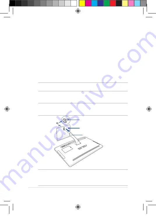
Assembling the base

1. 

Place the ASUS All-in-One PC on a flat and stable surface such as 

a table or desk.

2. 

Align and attach the base to the stand. Ensure that the stand is 

fitted firmly and aligned properly to the base.

NOTE:  

The stand fits to the base in one orientation only. 

3.  

Secure the base to the stand with the bundled stand screw. 

NOTE:

  The bundled stand screw is tool-less by design but you can also 

use a Phillips or a flat screwdriver, a coin, or a token to install it.

NOTE: 

The illustration above is for reference only. The actual All-in-One 

PC may slightly vary depending on the model but the installation steps 

remains the same.

base

stand screw

stand

E9540_ET1801I User Guide.indd   21

7/24/2014   2:35:19 PM

Summary of Contents for ET1801I

Page 1: ...ET1801I User Guide E9540_ET1801I User Guide indd 1 7 24 2014 2 35 16 PM ...

Page 2: ...ITMENT BY ASUS ASUS ASSUMES NO RESPONSIBILITY OR LIABILITY FOR ANY ERRORS OR INACCURACIES THAT MAY APPEAR IN THIS MANUAL INCLUDING THE PRODUCTS AND SOFTWARE DESCRIBED IN IT Copyright 2014 ASUSTeK COMPUTER INC All Rights Reserved LIMITATION OF LIABILITY Circumstances may arise where because of a default on ASUS part or other liability you are entitled to recover damages from ASUS In each such insta...

Page 3: ...rning 11 Package contents 12 Chapter 1 Hardware Setup Getting to know your ASUS All in One PC 13 Front view 13 Rear view 15 Side view 18 Chapter 2 Using your ASUS All in One PC Assembling the base 21 Positioning your ASUS All in One PC 22 Connecting a wired keyboard and mouse 23 Connecting a wireless keyboard and mouse optional 24 Powering on your ASUS All in One PC 25 E9540_ET1801I User Guide ind...

Page 4: ...ia the HDMI output port 46 Connecting to the Internet 48 Setting up a Wi Fi connection in Windows 8 1 48 Configuring your Wi Fi bandwidth 49 Wired connection 50 Turning your ASUS All in One PC off 52 Chapter 4 Recovering your system Entering the BIOS Setup 53 Quickly enter the BIOS 53 Recovering your system 54 Resetting your PC 54 Recovering from a system image file 55 Removing everything and rein...

Page 5: ...ormations concernant l exposition aux frequences radio RF 64 India RoHS 64 Declaration of Conformity R TTE directive 1999 5 EC 65 Wireless Operation Channel for Different Domains 65 CE Mark Warning 66 CE marking for devices without wireless LAN Bluetooth 66 CE marking for devices with wireless LAN Bluetooth 66 REACH 68 Global Environmental Regulation Compliance and Declaration 68 ASUS Recycling Ta...

Page 6: ...with information on using your ASUS All in One PC Chapter 3 Working with Windows 8 1 This chapter provides an overview of using Windows 8 1 in your ASUS All in One PC Chapter 4 Recovering your system This chapter provides recovery options for your ASUS All in One PC Chapter 5 Upgrading your ASUS All in One PC This chapter guides you through the process of replacing and upgrading parts of your All ...

Page 7: ...s message contains additional information and tips that can help complete tasks WARNING This message contains important information that must be followed to keep you safe while performing tasks and prevent damage to your device s data and components Typography Bold This indicates a menu or an item that must be selected Italic This indicates sections that you can refer to in this manual E9540_ET180...

Page 8: ...ges may vary with territories Visit the ASUS website at www asus com for the latest information Icons The icons below indicate the devices you can use for completing a series of tasks or procedures on your ASUS All in One PC optional Use the wired wireless mouse optional Use the wired wireless keyboard E9540_ET1801I User Guide indd 8 7 24 2014 2 35 17 PM ...

Page 9: ...these openings Ensure that you leave plenty of space around the system for ventilation Never insert objects of any kind into the ventilation openings Use this product in environments with ambient temperatures between 0 C and 40 C If you use an extension cord ensure that the total ampere rating of the devices plugged into the extension cord does not exceed its ampere rating Care during use Do not w...

Page 10: ...f the screen Do not spray the cleaner directly on the screen Do not use an abrasive cleaner or a coarse cloth when cleaning the screen If you encounter the following technical problems with the product unplug the power cord and contact a qualified service technician or your retailer The power cord or plug is damaged Liquid has been spilled into the system The system does not function properly even...

Page 11: ... pressure produced by the earphones or headphones Adapter 1 Adapter specifications Input voltage 100 240Vac Input frequency 50 60Hz Rating output voltage 19Vdc 2 It is recommended that the power socket is in close proximity to the ASUS All in One PC DC Fan Warning Please note that the DC fan is a moving part and can cause harm when used improperly Keep away from the fan when using the product E954...

Page 12: ...tailer The keyboard mouse and power supply illustrations are for reference only Actual product specifications may vary with territories ASUS All in One PC AC adapter Power cord Warranty card Keyboard optional Mouse optional Quick User Guide Quick Start Guide E9540_ET1801I User Guide indd 12 7 24 2014 2 35 17 PM ...

Page 13: ...r ASUS All in One PC Chapter 1 Hardware Setup Front view buttons on the bottom panel of the AiO Camera The built in camera allows you to take pictures or record videos using your ASUS All in One PC E9540_ET1801I User Guide indd 13 7 24 2014 2 35 18 PM ...

Page 14: ...g features for photos videos and other multimedia files Power indicator This LED power indicator lights up when the ASUS All in One PC is turned on or on sleep mode Hard Disk Drive HDD indicator This LED indicates hard disk drive activity Brightness adjust These buttons allows you to adjust the brightness or contrast settings Volume adjust These buttons allows you to adjust the system volume Power...

Page 15: ...ASUS All in One PC ET1801I 15 Rear view E9540_ET1801I User Guide indd 15 7 24 2014 2 35 18 PM ...

Page 16: ...ort This 8 pin RJ 45 LAN port supports a standard Ethernet cable for connection to a local network HDMI output port Connect this port with devices equipped with an HDMI input port such as an LCD monitor or projector USB 3 0 ports These Universal Serial Bus 3 0 USB 3 0 ports connect to USB 3 0 devices such as a mouse printer scanner camera and others USB 2 0 ports These USB Universal Serial Bus por...

Page 17: ...nt This compartment secures the RAM random access memory module of your All in One PC IMPORTANT For more information on how to add or upgrade the RAM module refer to the Installing a Random access Memory module section E9540_ET1801I User Guide indd 17 7 24 2014 2 35 19 PM ...

Page 18: ...ne PC has a built in memory card reader slot that supports MMC SD SDHC SDXC cards USB 3 0 ports These Universal Serial Bus 3 0 USB 3 0 ports connect to USB 3 0 devices such as a mouse printer scanner camera and others The lower port supports AI Charger II E9540_ET1801I User Guide indd 18 7 24 2014 2 35 19 PM ...

Page 19: ...ot work WARNING Use the manual eject hole only when the electronic eject button does not work Optical Disk Drive electronic eject button Press this button to eject the optical drive tray You can also eject the drive tray using your media player or by right clicking the optical drive icon in Windows File Explorer and clicking Eject Optical Drive on selected models This support compact discs CD digi...

Page 20: ...__________________________________________________________ ____________________________________________________________ ____________________________________________________________ ____________________________________________________________ ____________________________________________________________ ____________________________________________________________ ____________________________________...

Page 21: ...OTE The stand fits to the base in one orientation only 3 Secure the base to the stand with the bundled stand screw NOTE The bundled stand screw is tool less by design but you can also use a Phillips or a flat screwdriver a coin or a token to install it NOTE The illustration above is for reference only The actual All in One PC may slightly vary depending on the model but the installation steps rema...

Page 22: ...US All in One PC on a flat surface such as a table or desk 2 Tilt the display to an angle between 5o to 25o IMPORTANT Avoid adjusting the display to an angle beyond the recommended values or you may risk damaging the ASUS All in One PC E9540_ET1801I User Guide indd 22 7 24 2014 2 35 20 PM ...

Page 23: ...ouse Connect the keyboard and the mouse to the USB ports on the rear NOTE To fully maximize your AiO PC s AI Charger II feature use the lower USB 3 0 port to charge smart devices or MP3 players on the side panel E9540_ET1801I User Guide indd 23 7 24 2014 2 35 20 PM ...

Page 24: ...s above are for reference only Actual hardware and specifications of the optional wired or wireless keyboard and mouse may vary Connecting a wireless keyboard and mouse optional 1 Install batteries into the wireless keyboard and mouse 2 Connect the wireless dongle for keyboard and mouse to a USB port on the rear or on the side panel NOTE We recommend to use the USB 2 0 port for keyboard and mouse ...

Page 25: ...anel 4 of the ASUS All in One PC to power on the system WARNING DO NOT connect the AC power cord to an AC outlet prior to connecting the DC plug to the system Doing so may damage the AC DC adapter NOTE For details on turning off your ASUS All in One PC refer to the section Turning your ASUS All in One PC off in Working with Windows 8 1 E9540_ET1801I User Guide indd 25 7 24 2014 2 35 20 PM ...

Page 26: ...__________________________________________________________ ____________________________________________________________ ____________________________________________________________ ____________________________________________________________ ____________________________________________________________ ____________________________________________________________ ____________________________________...

Page 27: ...a few minutes until the setup screen appears 2 From the setup screen pick your region and a language to use on your ASUS All in One PC 3 Carefully read the License Terms Select I accept 4 Follow the onscreen instructions to configure the following basic items Personalize Get online Settings Your account 5 After configuring the basic items Windows 8 1 proceeds to install your apps and preferred set...

Page 28: ...le working on your ASUS All in One PC Start screen The Start screen appears after successfully signing in to your user account It helps organize all the applications you need in just one place Windows Apps These are apps pinned on the Start screen and displayed on tiled format for easy access NOTE Some apps require signing in to your Microsoft account before they are fully launched E9540_ET1801I U...

Page 29: ...s allow you to launch programs and access the settings of your ASUS All in One PC The functions in these hotspots can be activated using your mouse Hotspots on a running app Hotspots on the Start screen E9540_ET1801I User Guide indd 29 7 24 2014 2 35 21 PM ...

Page 30: ... slide down to show all running apps lower left corner From a running app screen Hover your mouse pointer on the lower left corner then tap click to go back to the Start screen NOTE You can also press the Windows key on your keyboard to go back to the Start screen From the Start screen Hover your mouse pointer on the lower left corner then tap click to go back to that app E9540_ET1801I User Guide ...

Page 31: ... a new location NOTE This hotspot function only works on a running app or when you want to use the Snap feature For more details refer to the Snap feature under Working with Windows apps upper or lower right corner Hover your mouse pointer on the upper or lower right corner to launch the Charms bar E9540_ET1801I User Guide indd 31 7 24 2014 2 35 21 PM ...

Page 32: ...tart screen while on Desktop mode and on any app that is currently open onscreen Start button on the Start screen NOTE The actual color of your Start button varies depending on the display settings you chose for your Start screen Hover your mouse pointer over the left corner of your Start screen or any opened app to call out the Start button E9540_ET1801I User Guide indd 32 7 24 2014 2 35 21 PM ...

Page 33: ...access to some of the programs inside Windows 8 1 when you right click on the Start button The context menu also includes the following shut down options for your ASUS All in One PC sign out sleep shut down restart Start button on Desktop mode E9540_ET1801I User Guide indd 33 7 24 2014 2 35 22 PM ...

Page 34: ...f your apps onscreen To customize the settings of your Start screen 1 Launch the Desktop 2 Right click anywhere on the taskbar except on the Start button to launch the pop up window 3 Click Properties then select the Navigation tab to tick the Navigation and Start screen options you want to use 4 Tap click Apply to save the new settings then exit E9540_ET1801I User Guide indd 34 7 24 2014 2 35 22 ...

Page 35: ...l or optional keyboard and mouse to launch customize and close apps Launching apps Position your mouse pointer over the app then left click or tap once to launch it Press twice then use the arrow keys to browse through the apps Press to launch an app E9540_ET1801I User Guide indd 35 7 24 2014 2 35 22 PM ...

Page 36: ... the Start screen using any of the following options Moving apps Double click on the app then drag and drop the app to a new location Right click on the app to activate the Customize bar then click and select an app tile size Resizing apps E9540_ET1801I User Guide indd 36 7 24 2014 2 35 22 PM ...

Page 37: ...en wait for the pointer to change to a hand icon 2 Drag then drop the app to the bottom of the screen to close it From the running app s screen press Closing apps Right click on the app to activate the Customize bar then click Unpinning apps E9540_ET1801I User Guide indd 37 7 24 2014 2 35 22 PM ...

Page 38: ...plications through the Apps screen NOTE Actual apps shown onscreen may vary per model The following screenshot is for reference only Launching the Apps screen Launch the Apps screen using the following options On the Start screen click the button From the Start screen Press then press E9540_ET1801I User Guide indd 38 7 24 2014 2 35 23 PM ...

Page 39: ... pin more apps on the Start screen using the following options 1 Launch the All Apps screen 2 Right click on the apps that you want to add on the Start screen 3 Click on the icon to pin the selected apps on the Start screen E9540_ET1801I User Guide indd 39 7 24 2014 2 35 23 PM ...

Page 40: ...r that can be triggered on the right side of your screen It consists of several tools that allow you to share applications and provide quick access for customizing the settings of your ASUS All in One PC Charms bar E9540_ET1801I User Guide indd 40 7 24 2014 2 35 23 PM ...

Page 41: ...ail Start This charm reverts the display back to the Start screen From the Start screen you can also use this to revert back to a recently opened app Devices This charm allows you to access and share files with the devices attached to your ASUS All in One PC such as an external display or printer Settings This charm allows you to access the PC settings of your ASUS All in One PC E9540_ET1801I User...

Page 42: ...ASUS All in One PC ET1801I 42 Snap feature The Snap feature displays two apps side by side allowing you to work or switch between apps Snap bar E9540_ET1801I User Guide indd 42 7 24 2014 2 35 23 PM ...

Page 43: ... screen 3 Once the pointer changes to a hand icon drag then drop the app to the left or right side of the display panel 4 Launch another app 1 Launch the app you wish to snap 2 Press and the left or right arrow key to snap the app to the left or right pane 3 Launch another app This app is automatically placed in the empty pane E9540_ET1801I User Guide indd 43 7 24 2014 2 35 23 PM ...

Page 44: ...Switches between the Start screen and the last running app Launches the desktop Launches the This ASUS All in One PC window on Desktop mode Opens the File option from the Search charm Opens the Share charm Opens the Settings charm Opens the Devices charm Activates the Lock screen Minimizes all currently active windows E9540_ET1801I User Guide indd 44 7 24 2014 2 35 23 PM ...

Page 45: ...harm Opens the Run window Opens Ease of Access Center Opens the Settings option under the Search charm Opens the context menu of the Start button Launches the magnifier icon and zooms in your screen Zooms out your screen Opens the Narrator Settings E9540_ET1801I User Guide indd 45 7 24 2014 2 35 24 PM ...

Page 46: ...s 3 From the Playback screen select Digital Audio HDMI 4 Click Configure and the Speaker Setup window pops up Setting up a secondary display via the HDMI output port If you want to use a high definition TV as an audio output device connect it to the Home Theater ASUS All in One PC and follow the steps below to configure the audio settings To configure the audio output via an HDMI device E9540_ET18...

Page 47: ... All in One PC ET1801I 47 5 Select Stereo and click Next 6 Tick the Front left and right option and click Next 7 Click Finish to exit the speaker setup E9540_ET1801I User Guide indd 47 7 24 2014 2 35 24 PM ...

Page 48: ...ws 8 1 1 Launch the Charm bar from the Start screen or from any application mode NOTE For details refer to the section Charm bar under Working with Windows apps 2 From the Charm bar select Settings and click the network icon 3 Select the wireless network that you want to connect to from the list 4 Click Connect NOTE You may be prompted to enter a security key to connect to a secured wireless netwo...

Page 49: ...ons 4 In the Wi Fi status window select Properties Configure to launch your current network adapter s properties 5 In the your current network adapter properties window select the Advanced tab 6 In the Advanced tab select Bandwidth Capability under the Property option then select your preferred bandwidth setting by clicking on the drop down box below Value 7 Click OK to save and exit E9540_ET1801I...

Page 50: ... Service Provider ISP for details or assistance in setting up your Internet connection Configuring a dynamic IP PPPoE network connection To configure a dynamic IP PPPoE or static IP network connection 1 From the Start screen click Desktop to launch the Desktop mode 2 FromtheWindows taskbar right clickthenetworkicon and click Open Network and Sharing Center 3 From the Open Network and Sharing Cente...

Page 51: ...h the configuration 12 Click the network icon in the taskbar and click the connection you just created 13 Enter your user name and password Click Connect to connect to the Internet Configuring a static IP network connection To configure a static IP network connection 1 Repeat steps 1 to 4 of the previous section Configuring a dynamic IP PPPoE network connection 2 Click Use the following IP address...

Page 52: ...own your ASUS All in One PC Tap click from the Charms bar then tap click Shut down to do a normal shutdown If your ASUS All in One PC is unresponsive press and hold the power button for at least four 4 seconds until your ASUS All in One PC turns off E9540_ET1801I User Guide indd 52 7 24 2014 2 35 24 PM ...

Page 53: ...ou have installed a new system component that requires further BIOS settings or update WARNING Inappropriate BIOS settings may result to instability or boot failure We strongly recommend that you change the BIOS settings only with the help of a trained service personnel Quickly enter the BIOS To access the BIOS When your ASUS All in One PC is off press the power button for at least four 4 seconds ...

Page 54: ...this option To reset your PC 1 Press F9 during bootup IMPORTANT To go through POST follow any of the ways described in the section Quickly enter the BIOS in Chapter 3 2 From the screen click Troubleshoot 3 Select Reset your PC 4 Click Next 5 Select Only the drive where the Windows is installed 6 Select Just remove my files 7 Click Reset E9540_ET1801I User Guide indd 54 7 24 2014 2 35 24 PM ...

Page 55: ... To create a USB recovery drive 1 Launch the Control Panel from the All Apps screen NOTE For details refer to Launching the All Apps screen under Working with Windows apps 2 From the Control Panel s System and Security click Find and fix problems 3 Click Recovery Create a recovery drive 4 Click Next 5 SelecttheUSBstoragedevicewhereyouwanttocopytherecovery files 6 Click Next 7 Click Create Wait for...

Page 56: ...to use this option IMPORTANT Back up all your data before using this option NOTE This process may take a while to complete 1 Launch the Charms bar 2 Click Settings Change PC Settings General 3 Scroll down to view the Remove everything and reinstallWindows option Under this option click Get Started 4 Followtheonscreeninstructionstocompletethereinstallationand reset process E9540_ET1801I User Guide ...

Page 57: ...unication lines and power connector such as external power supply battery pack etc before removing the compartment cover IMPORTANT Visit an authorized service center or retailer for information on RAM module upgrades for your ASUS All in One PC Purchase RAM modules from authorized retailers of this ASUS All in One PC to ensure maximum compatibility and reliability NOTE The appearance of the RAM mo...

Page 58: ...rew of the ASUS All in One PC s compartment cover 2 Pull out the compartment cover and remove it completely from your ASUS All in One PC Set aside 3 Remove the metal cover then set aside metal cover compartment cover E9540_ET1801I User Guide indd 58 7 24 2014 2 35 25 PM ...

Page 59: ... both hands in performing this step The RAM module fits in one orientation only If it does not fit try reversing it Ensure that the RAM module is seated securely in place The side notches of the RAM module should be firmly fixed in place 6 Replace the metal cover 7 Replace the compartment cover 30o angle notches E9540_ET1801I User Guide indd 59 7 24 2014 2 35 25 PM ...

Page 60: ...ASUS All in One PC ET1801I 60 8 Secure the compartment cover using the screw that you removed earlier in step 1 E9540_ET1801I User Guide indd 60 7 24 2014 2 35 25 PM ...

Page 61: ...nterference to radio communications However there is no guarantee that interference will not occur in a particular installation If this equipment does cause harmful interference to radio or television reception which can be determined by turning the equipment off and on the user is encouraged to try to correct the interference by one or more of the following measures Reorient or relocate the recei...

Page 62: ...with any other antenna or transmitter This device complies with Industry Canada licence exempt RSS standard s Operation is subject to the following two conditions 1 this device may not cause interference and 2 this device must accept any interference including interference that may cause undesired operation of the device RF exposure warning The equipment complies with FCC RF exposure limits set fo...

Page 63: ...ase avoid direct contact to the transmitting antenna during transmitting End users must follow the specific operating instructions for satisfying RF exposure compliance Operation is subject to the following two conditions This device may not cause interference and This device must accept any interference including interference that may cause undesired operation of the device Canada Industry Canada...

Page 64: ...les interferences qui peuvent affecter son fonctionnement Informations concernant l exposition aux frequences radio RF La puissance de sortie emise par l appareil de sans fil est inferieure a la limite d exposition aux frequences radio d Industry Canada IC Utilisez l appareil de sans fil de facon a minimiser les contacts humains lors du fonctionnement normal India RoHS This product complies with t...

Page 65: ...cording to EN 60950 Protection requirements for electromagnetic compatibility in Article 3 1b Testing for electromagnetic compatibility in EN 301 489 1 EN 301 489 17 Effective use of the radio spectrum as in Article 3 2 Radio test suites according to EN 300 328 2 Wireless Operation Channel for Different Domains N America 2 412 2 462 GHz Ch01 through CH11 Japan 2 412 2 484 GHz Ch01 through Ch14 Eur...

Page 66: ...his device complies with the requirements of the EEC directives 2004 108 EC Electromagnetic compatibility and 2006 95 EC Low voltage directive CE marking for devices with wireless LAN Bluetooth This equipment complies with the requirements of Directive 1999 5 EC of the European Parliament and Commission from 9 March 1999 governing Radio and Telecommunications Equipment and mutual recognition of co...

Page 67: ...o Liquids DO NOT expose to or use near liquids rain or moisture This product is not waterproof or oil proof This symbol of the crossed out wheeled bin indicates that the product electrical electronic equipment and mercury containing button cell battery shouldnotbeplacedinmunicipalwaste Checklocalregulations for disposal of electronic products DONOTthrowthebatteryinmunicipalwaste Thesymbolofthecros...

Page 68: ...S disclose the relevant information based on regulation requirements Please refer to http csr asus com english Compliance htm for information disclosure based on regulation requirements ASUS is complied with Japan JIS C 0950 Material Declarations EU REACH SVHC Korea RoHS ASUS Recycling Takeback Services ASUS recycling and takeback programs come from our commitment to the highest standards for prot...

Page 69: ... maintain electrical safety a coating is applied to insulate the device except on the areas where the I O ports are located Prevention of Hearing Loss To prevent possible hearing damage do not listen at high volume levels for long periods E9540_ET1801I User Guide indd 69 7 24 2014 2 35 26 PM ...

Page 70: ...anagement feature is enabled by default The monitor and computer are automatically set to sleep after 10 and 30 minutes of user inactivity To wake your computer click the mouse or press any key on the keyboard Please visit http www energy gov powermanagement for detail information on power management and its benefits to the environment In addition please visit http www energystar gov for detail in...

Page 71: ...__________________________________________________________ ____________________________________________________________ ____________________________________________________________ ____________________________________________________________ ____________________________________________________________ ____________________________________________________________ ____________________________________...

Page 72: ...c Tel 886 2 2894 3447 Address 4F No 150 LI TE RD PEITOU TAIPEI 112 TAIWAN Authorised representative in Europe ASUSTeK Computer GmbH Address HARKORT STR 21 23 40880 RATINGEN GERMANY E9540_ET1801I User Guide indd 72 7 24 2014 2 35 26 PM ...

Reviews: