background image

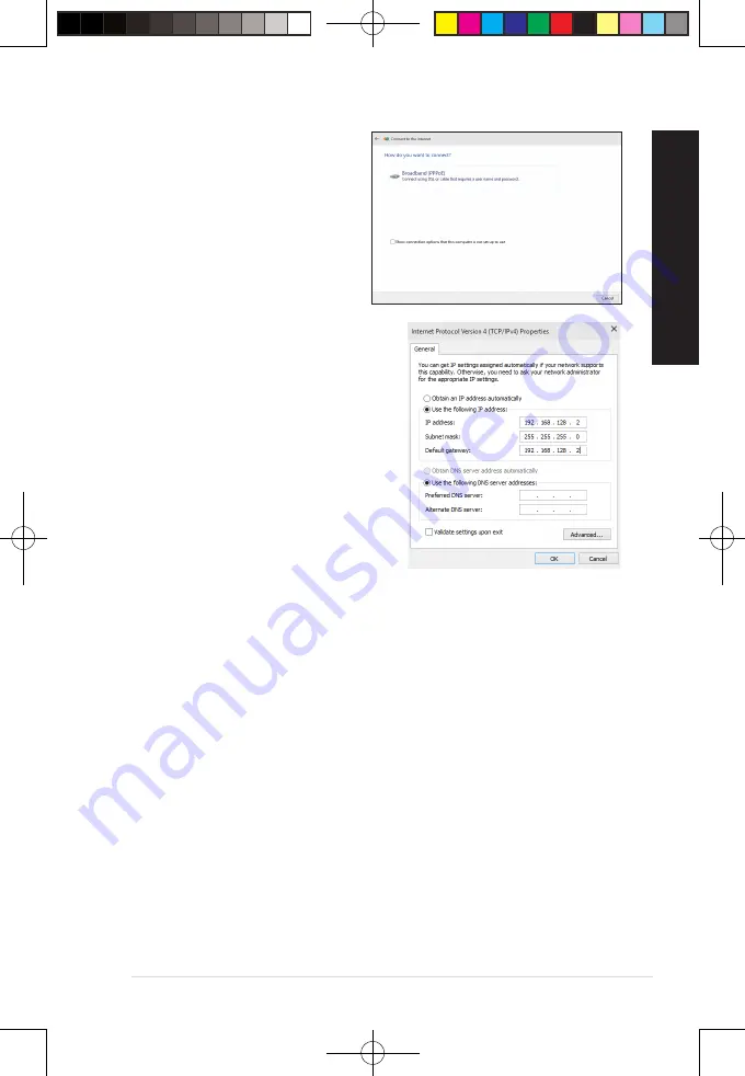
8. Select 

Broadband (PPPoE)

 and click 

Next

.

9. 

Follow the next onscreen instructions to 

complete the setup.

Configuring a static IP network connection

To configure a static IP network connection:

1. 

Repeat steps 1 to 4 of the previous section.

2 Click 

Use the following IP address

.

3. 

Enter the IP address, Subnet mask and Gateway 

from your service provider.

4. 

If needed, enter the preferred DNS Server 

address and alternative address.

5. 

When done, click 

OK

.

ASUS Desktop PC

47

ENGLISH

ENGLISH

E19621_D500MD_D700MD_UM.indd   47

E19621_D500MD_D700MD_UM.indd   47

3/1/2022   2:38:12 PM

3/1/2022   2:38:12 PM

Summary of Contents for D500MD

Page 1: ...ktop PC User Guide D700MD S700MD D700MDES M700MD D700MD_CZ D500MD S500MD D500MDES M500MD D500MD_CZ D500MD_IN E19621_D500MD_D700MD_UM indd 1 E19621_D500MD_D700MD_UM indd 1 3 1 2022 2 38 04 PM 3 1 2022 2 38 04 PM ...

Page 2: ...FOR ANY INDIRECT SPECIAL INCIDENTAL OR CONSEQUENTIAL DAMAGES INCLUDING DAMAGES FOR LOSS OF PROFITS LOSS OF BUSINESS LOSS OF USE OR DATA INTERRUPTION OF BUSINESS AND THE LIKE EVEN IF ASUS HAS BEEN ADVISED OF THE POSSIBILITY OF SUCH DAMAGES ARISING FROM ANY DEFECT OR ERROR IN THIS MANUAL OR PRODUCT SPECIFICATIONS AND INFORMATION CONTAINED IN THIS MANUAL ARE FURNISHED FOR INFORMATIONAL USE ONLY AND A...

Page 3: ...lays 35 Connecting an HDTV 36 Chapter 3 Using your computer Proper posture when using your Desktop PC 37 Using the memory card reader Optional 38 Using the optical drive on selected models only 39 Configuring the USB ports using the BIOS 40 Configuring the HDD security setting using the BIOS 41 Chapter 4 Connecting to the Internet Wired connection 43 Chapter 5 Using ASUS Business Manager ASUS Busi...

Page 4: ...wireless networks 60 Connecting to wired networks 61 Turning your computer off 61 Putting your computer to sleep 61 E19621_D500MD_D700MD_UM indd 4 E19621_D500MD_D700MD_UM indd 4 3 1 2022 2 38 04 PM 3 1 2022 2 38 04 PM ...

Page 5: ...ipment generates uses and can radiate radio frequency energy and if not installed and used in accordance with manufacturer s instructions may cause harmful interference to radio communications However there is no guarantee that interference will not occur in a particular installation If this equipment does cause harmful interference to radio or television reception which can be determined by turni...

Page 6: ...nce Statement Complies with the Canadian ICES 003 Class B specifications This device complies with RSS 210 of Industry Canada This Class B device meets all the requirements of the Canadian interference causing equipment regulations This device complies with Industry Canada license exempt RSS standard s Operation is subject to the following two conditions this device may not cause interference and ...

Page 7: ...cury hexavalent chromium polybrominated biphenyls PBBs and polybrominated diphenyl ethers PBDEs in concentrations exceeding 0 1 by weight in homogenous materials and 0 01 by weight in homogenous materials for cadmium except for the exemptions listed in Schedule II of the Rule Canadian Department of Communications Statement This digital apparatus does not exceed the Class B limits for radio noise e...

Page 8: ... transmitter subject to the conditions of the FCC Grant Bluetooth Industry Canada Statement This Class B device meets all requirements of the Canadian interference causing equipment regulations Cet appareil numérique de la Class B respecte toutes les exigences du Règlement sur le matériel brouilleur du Canada Simplified EU Declaration of Conformity ASUSTek Computer Inc hereby declares that this de...

Page 9: ...roducts manufactured from August 1 1976 Compliance is mandatory for products marketed in the United States WARNING Use of controls or adjustments or performance of procedures other than those specified herein or in the laser product installation guide may result in hazardous radiation exposure Optical Drive Safety Information Laser Safety Information Simplified UKCA Declaration of Conformity ASUST...

Page 10: ... the electrical outlet before relocating the system Seek professional assistance before using an adapter or extension cord These devices could interrupt the grounding circuit Ensure that your power supply is set to the correct voltage in your area If you are not sure about the voltage of the electrical outlet you are using contact your local power company If the power supply is broken do not try t...

Page 11: ...and other body parts away from any moving parts CAUTION DO NOT loosen the thumb screws to access the internal area of your device If service or repair is required return your device to an authorized service center WARNING Hot Internal replaceable parts and iron parts may cause burns Do not ingest battery Chemical Burn Hazard This product contains a coin button cell battery If the coin button cell ...

Page 12: ...t for detail information on power management and its benefits to the environment In addition please visit http www energystar gov for detail information on the ENERGY STAR joint program Note Energy Star is NOT supported on Freedos and Linux based products Where to find more information Refer to the following sources for additional information and for product and software updates ASUS website The A...

Page 13: ...t specifications may vary with different models ASUS Desktop PC Keyboard x1 Optional Mouse x1 Optional Power cord x1 Support DVD x1 Optional Recovery DVD x1 Optional Installation Guide ASUS mouse pad x 1 Optional Installation Guide x1 Warranty card x1 E19621_D500MD_D700MD_UM indd 13 E19621_D500MD_D700MD_UM indd 13 3 1 2022 2 38 06 PM 3 1 2022 2 38 06 PM ...

Page 14: ...14 E19621_D500MD_D700MD_UM indd 14 E19621_D500MD_D700MD_UM indd 14 3 1 2022 2 38 06 PM 3 1 2022 2 38 06 PM ...

Page 15: ...ead the ASUS Warranty Card before setting up your ASUS Desktop PC The Desktop PC does not support Windows 7 operating system ASUS is not responsible for any loss or damage incurred by installing Window 7 Be careful when handling the desktop PC to prevent the risk of injury IMPORTANT Do not use this Desktop PC for cryptocurrency mining consuming a vast amount of electricity and time to gain convert...

Page 16: ... to USB 3 2 Gen 1 devices such as a mouse printer scanner camera PDA and others 8 USB 3 2 Gen 2 ports The Universal Serial Bus 3 2 Gen 2 USB 3 2 Gen 2 ports connect to USB 3 2 Gen 2 devices such as a mouse printer scanner camera PDA and others 9 USB 2 0 ports These Universal Serial Bus 2 0 USB 2 0 ports connect to USB 2 0 devices such as a mouse printer scanner camera PDA and others 10 USB 3 2 Gen...

Page 17: ...onnects to a headphone or speaker You can also connect your headset or an external microphone 7 USB 3 2 Gen 1 ports The Universal Serial Bus 3 2 Gen 1 USB 3 2 Gen 1 ports connect to USB 3 2 Gen 1 devices such as a mouse printer scanner camera PDA and others 8 USB 3 2 Gen 2 ports The Universal Serial Bus 3 2 Gen 2 USB 3 2 Gen 2 ports connect to USB 3 2 Gen 2 devices such as a mouse printer scanner ...

Page 18: ... connects to a headphone or speaker In a 4 5 1 or 7 1 channel configuration the function of this port becomes Front Speaker Out 8 Line In port light blue This port connects to a tape CD DVD player or other audio sources Refer to the audio configuration table below for the function of the audio ports in the 2 4 5 1 or 7 1 channel configuration Audio 2 4 5 1 or 7 1 channel configuration Port Headset...

Page 19: ...network hub 13 Serial ports optional These 9 pin COM ports are for pointing devices or other serial devices 14 Expansion slot brackets Remove the expansion slot bracket when installing an expansion card 15 Power connector Plug the power cord to this connector RATING 115 230Vac 50 60Hz 4 2A Global 220Vac 50Hz 2A China 115Vac 50 60Hz 4A Taiwan 115 230Vac 50 60Hz 4 2A JP KR 10 Parallel port optional ...

Page 20: ...speaker In a 4 5 1 or 7 1 channel configuration the function of this port becomes Front Speaker Out 7 Line In port light blue This port connects to a tape CD DVD player or other audio sources Refer to the audio configuration table below for the function of the audio ports in the 2 4 5 1 or 7 1 channel configuration Audio 2 4 5 1 or 7 1 channel configuration Port Headset 2 channel 4 channel 5 1 cha...

Page 21: ...GREEN 1Gbps connection LAN port LED indications 11 LAN RJ 45 port This port allows Gigabit connection to a Local Area Network LAN through a network hub 12 Serial ports optional These 9 pin COM ports are for pointing devices or other serial devices 13 Expansion slot brackets Remove the expansion slot bracket when installing an expansion card 9 Parallel port optional This 25 pin port connects a para...

Page 22: ...ut ports Connect your monitor to the onboard display output port To connect an external monitor using the onboard display output ports 1 Connect a monitor to a display output port on the rear panel of your computer 2 Plug the monitor to a power source D700MD S700MD D700MDES M700MD D700MD_CZ 22 Chapter 1 Getting started ENGLISH E19621_D500MD_D700MD_UM indd 22 E19621_D500MD_D700MD_UM indd 22 3 1 202...

Page 23: ...a display output port on the graphics card To connect multiple external monitors to your computer refer to Connecting multiple external display of this guide for details D500MD S500MD D500MDES M500MD D500MD_CZ D500MD_IN ASUS Desktop PC 23 ENGLISH E19621_D500MD_D700MD_UM indd 23 E19621_D500MD_D700MD_UM indd 23 3 1 2022 2 38 08 PM 3 1 2022 2 38 08 PM ...

Page 24: ... to the USB ports on the rear panel of your computer D700MD S700MD D700MDES M700MD D700MD_CZ D500MD S500MD D500MDES M500MD D500MD_CZ D500MD_IN 24 Chapter 1 Getting started ENGLISH E19621_D500MD_D700MD_UM indd 24 E19621_D500MD_D700MD_UM indd 24 3 1 2022 2 38 08 PM 3 1 2022 2 38 08 PM ...

Page 25: ...other end to a power source For safety purposes ONLY connect the power cord to a grounded electrical outlet D700MD S700MD D700MDES M700MD D700MD_CZ D500MD S500MD D500MDES M500MD D500MD_CZ D500MD_IN ASUS Desktop PC 25 ENGLISH E19621_D500MD_D700MD_UM indd 25 E19621_D500MD_D700MD_UM indd 25 3 1 2022 2 38 09 PM 3 1 2022 2 38 09 PM ...

Page 26: ...our monitor ON 2 Press the power button on your computer 3 Wait until the operating system loads automatically Power button D700MD S700MD D700MDES M700MD D700MD_CZ D500MD S500MD D500MDES M500MD D500MD_CZ D500MD_IN Power button 26 Chapter 1 Getting started ENGLISH E19621_D500MD_D700MD_UM indd 26 E19621_D500MD_D700MD_UM indd 26 3 1 2022 2 38 09 PM 3 1 2022 2 38 09 PM ...

Page 27: ...e or disable the front and rear USB 3 2 Gen 2 Type C USB 3 2 Gen 1 USB 3 2 Gen 2 and USB 2 0 ports individually from the BIOS Setup Refer to the Configuring the USB ports using the BIOS section in Chapter 3 of this user manual for details D700MD S700MD D700MDES M700MD D700MD_CZ D500MD S500MD D500MDES M500MD D500MD_CZ D500MD_IN ASUS Desktop PC 27 ENGLISH Chapter 2 Connecting devices to your compute...

Page 28: ...peaker When you connect an external audio device such as earphone or speaker you need to enable the audio device output For details refer to the section Changing to the external audio output When you disconnect the audio device you need to manually change the audio output to the internal speaker from the Control Panel D700MD S700MD D700MDES M700MD D700MD_CZ D500MD S500MD D500MDES M500MD D500MD_CZ ...

Page 29: ...Connecting Headphone and Mic D700MD S700MD D700MDES M700MD D700MD_CZ ASUS Desktop PC 29 ENGLISH E19621_D500MD_D700MD_UM indd 29 E19621_D500MD_D700MD_UM indd 29 3 1 2022 2 38 09 PM 3 1 2022 2 38 09 PM ...

Page 30: ...MD S500MD D500MDES M500MD D500MD_CZ D500MD_IN 30 Chapter 2 Connecting devices to your computer ENGLISH E19621_D500MD_D700MD_UM indd 30 E19621_D500MD_D700MD_UM indd 30 3 1 2022 2 38 10 PM 3 1 2022 2 38 10 PM ...

Page 31: ...necting 2 channel Speakers LINE OUT Connecting 4 channel Speakers LINE OUT ASUS Desktop PC 31 ENGLISH E19621_D500MD_D700MD_UM indd 31 E19621_D500MD_D700MD_UM indd 31 3 1 2022 2 38 10 PM 3 1 2022 2 38 10 PM ...

Page 32: ... D700MD S700MD D700MDES M700MD D700MD_CZ Connecting 5 1 channel Speakers LINE OUT 32 Chapter 2 Connecting devices to your computer ENGLISH E19621_D500MD_D700MD_UM indd 32 E19621_D500MD_D700MD_UM indd 32 3 1 2022 2 38 10 PM 3 1 2022 2 38 10 PM ...

Page 33: ...LINE OUT D500MD S500MD D500MDES M500MD D500MD_CZ D500MD_IN ASUS Desktop PC 33 ENGLISH E19621_D500MD_D700MD_UM indd 33 E19621_D500MD_D700MD_UM indd 33 3 1 2022 2 38 10 PM 3 1 2022 2 38 10 PM ...

Page 34: ...vice such as earphone or speaker to the rear Line Out port The Audio Manager screen automatically pops up For the location of the rear Line Out port refer to the section Getting to know your computer 2 Tick Front Speaker Out then click OK 3 Tick Line In then click OK The audio output will now be from the external audio device The Audio Manager screenshots above are for reference only E19621_D500MD...

Page 35: ...mputer and connect the power cords to the monitors Refer to the Setting up your computer section in Chapter 1 for details on how to connect a monitor to your computer 3 Turn on your computer 4 From the Start menu click Settings System Display 5 Configure the settings for your displays For some graphics cards only the monitor that is set to be the primary display has display during POST The dual di...

Page 36: ... is purchased separately To get the best display performance ensure that your HDMI cable is less than 15 meters D700MD S700MD D700MDES M700MD D700MD_CZ D500MD S500MD D500MDES M500MD D500MD_CZ D500MD_IN 36 Chapter 2 Connecting devices to your computer ENGLISH E19621_D500MD_D700MD_UM indd 36 E19621_D500MD_D700MD_UM indd 36 3 1 2022 2 38 10 PM 3 1 2022 2 38 10 PM ...

Page 37: ...er than your hips to relax the backs of your thighs If necessary use a footrest to raise the level of your knees Adjust the back of your chair so that the base of your spine is firmly supported and angled slightly backward Sit upright with your knees elbows and hips at an approximately 90º angle when you are at the PC Place the monitor directly in front of you and turn the top of the monitor scree...

Page 38: ...our files If AutoPlay is NOT enabled in your computer click File Explorer from the Start menu and then double click the memory card icon to access the data on it Each card slot has its own drive icon which is displayed on the File Explorer screen 3 When finished right click the memory card drive icon on the Computer screen click Eject and then remove the card Never remove cards while or immediatel...

Page 39: ...n optical disc To remove an optical disc 1 While the system is on do either of the following to eject the tray Press the eject button on the drive bay cover From the Start menu click File Explorer right click the CD DVD drive icon and click Eject 2 Remove the disc from the disc tray If AutoPlay is NOT enabled in your computer to access the data on an optical disc Click File Explorer from the Start...

Page 40: ...EZ Mode screen press F7 to enter the Advanced Mode From the Advanced Mode screen click Advanced Mode Security I O Interface Security USB Interface Security USB Port Control 3 Select the USB port that you want to enable or disable 4 Press Enter to enable or disable the selected USB port 5 Click Exit and select Save Changes Reset to save the changes made Refer to Chapter 1 for the location of the US...

Page 41: ...changes made Take note of this password which you would need to access the HDD To change the password for your HDD from the BIOS Setup 1 Follow steps 1 and 2 of the previous section to open the HDD Password screen 2 Select the Set Master Password item and press Enter 3 From the Enter Current Password box key in the current password then press Enter 4 From the Create New Password box key in a new p...

Page 42: ...42 Chapter 3 Using your computer ENGLISH E19621_D500MD_D700MD_UM indd 42 E19621_D500MD_D700MD_UM indd 42 3 1 2022 2 38 11 PM 3 1 2022 2 38 11 PM ...

Page 43: ...ect one end of an RJ 45 cable to the LAN RJ 45 port on the rear panel of your computer and the other end to a DSL cable modem Refer to the documentation that came with your DSL cable modem Modem RJ 45 cable D700MD S700MD D700MDES M700MD D700MD_CZ ASUS Desktop PC 43 ENGLISH Chapter 4 Connecting to the Internet E19621_D500MD_D700MD_UM indd 43 E19621_D500MD_D700MD_UM indd 43 3 1 2022 2 38 11 PM 3 1 2...

Page 44: ...ings Contact your network administrator for details or assistance in setting up your Internet connection For more details refer to the sections Configuring a dynamic IP PPPoE network connection or Configuring a static IP network connection D500MD S500MD D500MDES M500MD D500MD_CZ D500MD_IN Modem RJ 45 cable D700MD S700MD D700MDES M700MD D700MD_CZ 44 Chapter 4 Connecting to the Internet ENGLISH E196...

Page 45: ...ork connection To configure a dynamic IP PPPoE network connection 1 Launch Network and Sharing Center in either of these two ways a From the taskbar right click then click Open Network and Sharing Center b From the Start menu click Settings Network Internet Ethernet Network and Sharing Center 2 From the Open Network and Sharing Center screen click Change Adapter settings 3 Right click on your LAN ...

Page 46: ...E connection 7 Select Connect to the Internet and click Next 6 Return to the Network and Sharing Center and then click Set up a new connection or network 46 Chapter 4 Connecting to the Internet ENGLISH E19621_D500MD_D700MD_UM indd 46 E19621_D500MD_D700MD_UM indd 46 3 1 2022 2 38 12 PM 3 1 2022 2 38 12 PM ...

Page 47: ...ion 1 Repeat steps 1 to 4 of the previous section 2 Click Use the following IP address 3 Enter the IP address Subnet mask and Gateway from your service provider 4 If needed enter the preferred DNS Server address and alternative address 5 When done click OK ASUS Desktop PC 47 ENGLISH E19621_D500MD_D700MD_UM indd 47 E19621_D500MD_D700MD_UM indd 47 3 1 2022 2 38 12 PM 3 1 2022 2 38 12 PM ...

Page 48: ...48 Chapter 4 Connecting to the Internet ENGLISH E19621_D500MD_D700MD_UM indd 48 E19621_D500MD_D700MD_UM indd 48 3 1 2022 2 38 12 PM 3 1 2022 2 38 12 PM ...

Page 49: ...SUS computer For detailed information please refer to https www asus com support FAQ 1042634 The URL may be changed without notice ASUS Desktop PC 49 ENGLISH Chapter 5 Using ASUS Business Manager E19621_D500MD_D700MD_UM indd 49 E19621_D500MD_D700MD_UM indd 49 3 1 2022 2 38 12 PM 3 1 2022 2 38 12 PM ...

Page 50: ...50 Chapter 5 Using ASUS Business Manager ENGLISH E19621_D500MD_D700MD_UM indd 50 E19621_D500MD_D700MD_UM indd 50 3 1 2022 2 38 12 PM 3 1 2022 2 38 12 PM ...

Page 51: ... Delete keys on the keyboard then click Task Manager 2 Select the program that is not responding then click EndTask If the keyboard is not responding press and hold the Power button on your chassis until the computer shuts down Then press the Power button to turn it on I cannot connect to a wireless network using the ASUSWLAN Card on selected models only Ensure that you enter the correct network s...

Page 52: ...e documentation that came with your monitor for more troubleshooting information When using multiple monitors only one monitor has display Ensure that the both monitors are powered on During POST only the monitor connected to the VGA port has display The dual display function works only under Windows When a graphics card is installed on your computer ensure that you connect the monitors to the out...

Page 53: ...o the Line out port lime on the front panel or the rear panel Check if your speak is connected to an electrical source and turned on Adjust your speakers volume Ensure that your computer s system sounds are not Muted If it is muted the volume icon is displayed as To enable the system sounds click from the Windows notification area then click If it is not muted click and drag the slider to adjust t...

Page 54: ...other compatible power cord PSU Power supply unit problems Contact the ASUS Service Center about installing another PSU on your computer Display Problem Possible Cause Action No display output after turning the computer on Black screen The signal cable is not connected to the correct VGA port on your computer Connect the signal cable to the correct display port onboard VGA or discrete VGA port If ...

Page 55: ...y the anti virus software Close the anti virus software Driver problems Reinstall the LAN driver Audio Problem Possible Cause Action No Audio Speaker or headphone is connected to the wrong port Refer to your computer s User Guide for the correct port Disconnect and reconnect the speaker to your computer Speaker or headphone does not work Try using another speaker or headphone The front and back au...

Page 56: ... disk drive to ASUS Service Center for servicing Replace with a new hard disk drive Memory module problems Replace with compatible memory modules Remove the extra memory modules that you have installed then try again Contact the ASUS Service Center for assistance There is not enough air ventilation for your computer Move your computer to an area with better air flow Incompatible softwares are inst...

Page 57: ...use The CPU fan has been replaced Ensure that you are using a compatible or ASUS recommended CPU fan There is not enough air ventilation for the computer Ensure that your computer is working in an area with good air flow The system temperature is too high Update the BIOS If you know how to reinstall the motherboard try to clean the inner space of the chassis Contact the ASUS Service Center for ass...

Page 58: ...58 Chapter 6 Troubleshooting ENGLISH E19621_D500MD_D700MD_UM indd 58 E19621_D500MD_D700MD_UM indd 58 3 1 2022 2 38 13 PM 3 1 2022 2 38 13 PM ...

Page 59: ... appears The screenshots in this chapter are for reference only Start menu The Start menu is the main gateway to your computer s programs Windows apps folders and settings You can use the Start menu to do these common activities Start programs or Windows apps Open commonly used programs or Windows apps Adjust computer settings Get help with the Windows operating system Turn off your computer Log o...

Page 60: ...es using your computer s Wi Fi connection ConnectingWi Fi Connect your computer to a Wi Fi network by using the following steps 1 Click Tap the Wi Fi icon from the taskbar to enable Wi Fi 2 Select an access point from the list of available Wi Fi connections 3 Select Connect to start the network connection You may be prompted to enter a security key to activate the Wi Fi connection Bluetooth Use Bl...

Page 61: ...on then select Shut down to do a normal shutdown From the log in screen select the power icon then select Shut down Press to launch Shut Down Windows Select Shut down from the drop down list then select OK If your computer is unresponsive press and hold the power button for at least four 4 seconds until your computer turns off Putting your computer to sleep You can put your computer to Sleep mode ...

Reviews: