background image

16

GigaX Centralized Network Management User’s Manual

English

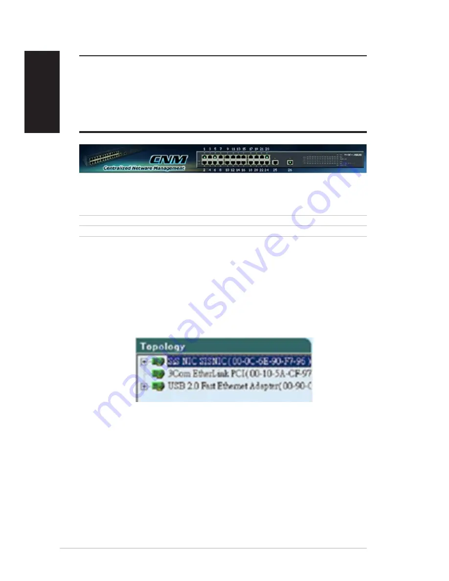
Figure 4.2. Top frame

Table 4.1. Description of Port Color

Figure 4.3. A Topology Frame

4.2 Functional Layout

The CNM window consists of three separate frames. The top frame has
switch logo and front panel as shown in Figure4.2. This frame remains on
the top of the browser window all the times and updates the LED status
periodically. The LED definition has been described as Table 2.1. Each port
shows different states by different colors, shown as Table 4.1.

Green Blinking port

Ethernet link is established

Black

No Ethernet link

The left frame, a topology frame as shown in Figure 4.3, contains all the
NICs in the manage station. Each NIC has a tree view to show the switches
that are discovered by CNM. You can click on any of these to display a
specific configuration of the switch.

Summary of Contents for Centralized Network Management

Page 1: ...e SPECIFICATIONS AND INFORMATION CONTAINED IN THIS MANUAL ARE FURNISHED FOR INFORMATIONAL USE ONLY AND ARE SUBJECT TO CHANGE AT ANY TIME WITHOUT NO TICE AND SHOULD NOT BE CONSTRUED AS A COMMITMENT BYASUS ASUS ASSUMES NO RESPONSIBILITY OR LIABILITY FOR ANY ERRORS OR INACCURACIES THAT MAY APPEAR IN THIS MANUAL INCLUDING THE PRODUCTS AND SOFTWARE DESCRIBED IN IT Copyright 2004 ASUSTeK COMPUTER INC Al...

Page 2: ...English Centralized Network Management GigaX Management Software User s Manual Product Name CNM Software Manual Revision 1 E1604 Release Date May 2004 ...

Page 3: ...Front Panel 1 7 2 3 Rear Panel 1 7 2 4 Technical Specifications 1 8 3 Quick Start Guide 1 9 3 1 Part 1 Connecting the Hardware 1 9 3 2 Part 2 Start the Switch 1 11 3 3 Management from CNM 1 13 4 Management Functions 1 15 4 1 Start CNM Program 1 15 4 2 Functional Layout 1 16 4 3 General Settings for CNM 1 18 4 4 Switch Topology 1 21 4 5 Switch Setup 1 24 4 6 System 1 25 4 7 Configuration 1 31 4 8 S...

Page 4: ...s 24 10 100BASE TX auto sensing Fast Ethernet switching ports 2 10 100 1000BASE T auto sensing Gigabit Ethernet switching ports Auto MDI MDIX support for 10 100BASE TX 10 100 1000BASE T ports 802 3 802 3u and 802 3ab compliant 8 8 Gbps switch capacity and 6 6 Mpps forwarding rate 8K MAC address cache with hardware assisted aging 802 3x flow control 802 1Q based tagged VLAN up to 32 VLANs 802 1p Co...

Page 5: ...lics are used to present the texts displayed or you type in the CNM user interface Boldface type text is used for items you select from menus and drop down lists 1 2 3 Special messages This document uses the following icons to call your attention to specific instructions or explanations Note Provides clarification or nonessential information on the current topic Definition Explains terms or acrony...

Page 6: ...asus com General Email tsd asus com General Fax 1 510 608 4555 Technical Support Support Email notebooktsd asus com Support Fax 1 502 933 8713 General Support 1 502 995 0883 Notebook Tel 1 510 739 3777 x5110 ASUS COMPUTER GmbH Germany Austria Web SiteAddress www asuscom de Online Contact www asuscom de sales General Telephone 49 2102 95990 General Fax 49 2102 959911 Technical Support Online Suppor...

Page 7: ... 2 Getting to Know the GigaX 1024P 2 1 Parts List In addition to this document the switch should come with the following GigaX 1024P managed switch AC Power cord Rack installation kit 2 brackets with 6 screws M3 x 6L Installation CD ROM Quick installation guide ...

Page 8: ...ted on this port Off No Ethernet link Amber On Ethernet link is established in 10 Mbps Flashing Data frames are being transmitted on this port DUPLEX COLLISION Amber On The port is operating in full duplex mode Flashing The port is operating in half duplex mode and collisions are occurring Off The port is operating in half duplex mode 10 100 1000 Gigabit ports form 25 to 26 STATUS Green On Link is...

Page 9: ...tions Physical Dimensions 43 5mm H X 444 mm W X 200mm D Environmental Ranges Operating temperature 10ºC to 50ºC 14ºF to 122ºF Storage temperature 40ºC to 70ºC 40ºF to 158ºF Operating humidity 15 to 90 Storage humidity 00 to 95 Power Input 100 240V AC 2 5A 50 60Hz Power Consumption 12W ...

Page 10: ... select a proper place to install the switch Please use the operating environment specifications as references to choose the installation place The Ethernet cable length from the switch to an attached device cannot exceed 100 meters 328 feet 3 1 1 Installing the Switch on a Flat Surface The switch should be installed on a level surface that can support the weight of the switches and their accessor...

Page 11: ...to the CNM installation guide for details Before starting the CNM application you have to connect the PC to the same network as the switch is attached to 3 2 2 Step 2 Connect to computers or a LAN You can use Ethernet cable to connect computers directly to the switch ports You can also connect hubs switches to the switch ports by Ethernet cables Note that both the crossover or straight through Eth...

Page 12: ...ew of Hardware Connections LED Indicators This LED Should be POWER Solid green to indicate that the device is turned on If this light is not on check if the power cord is attached to the switch and if it is plugged into a power source STATUS of Solid green amber to indicate that the device can communicate with your 10 100 ports LAN or flashing when the device is sending or receiving data from your...

Page 13: ... attached to the same network as the switch is Otherwise CNM will not be able to discover the switch Note This version of CNM only manages the switches in the same network 3 3 1 Switch Discovery and Management 1 Make sure that the switch is powered ON and that the CNM is installed on the management station 2 Click on the CNM shortcut icon in the desktop of the manage station to start the CNM appli...

Page 14: ...ery is done the left frame of the window will show the MAC addresses of the switches discovered by the CNM as Figure 3 3 4 Select the switch you want to manage by clicking on the MAC address then you can start to configure the switch by CNM 5 If the CNM cannot discover the switch you want to manage please repeat step 1 to 4 again Note The switch must be powered on and connect to your network befor...

Page 15: ...he cable then power cycle the switch You can manage the switch by default password Note To reset the password there must be no connection in the switch except the loop between port 3 and 4 3 3 3 Factory Default Setting You can reset the switch configuration back to factory default value by the similar steps as the password recovery Instead of looping port 3 and 4 use port 1 and 2 to make a loop 1 ...

Page 16: ...l CNM in a computer running Windows OS Refer to CNM installation guide for detail installation steps 2 The computer with CNM installed must be in the same network as the switches are 3 Make sure the switches are power on and the network links are good 4 Click the CNM icon on the PC s desktop A CNM window comes out as Figure 4 1 This computer becomes the manage station to the switches 5 Figure 4 1 ...

Page 17: ... the browser window all the times and updates the LED status periodically The LED definition has been described as Table 2 1 Each port shows different states by different colors shown as Table 4 1 Green Blinking port Ethernet link is established Black No Ethernet link The left frame a topology frame as shown in Figure 4 3 contains all the NICs in the manage station Each NIC has a tree view to show...

Page 18: ...ow the relationship of those switches as Figure 4 4 Figure 4 4 Tree view of the network topology The right frame displays the specified switch configurations or graphics for the statistics That is it displays different configuration layout for different model Section 4 5 will describe 1024P configuration in details You have to specify a switch by clicking one switch in the topology list ...

Page 19: ...ponding function icon in the tool bar 4 Update detect if the communications between the CNM station and the discovered switches is good or not The switch icon will show to indicate that the communication is broken 4 3 General Settings for CNM There are menu bar and tool bar on the top of the CNM window They offer general settings for CNM The Topology item provides the general network discovery man...

Page 20: ...d Switch add a switch to the topology tree manually A window pops out for this purpose as Figure 4 6 Select the network adapter you want the switch to attach to give the switch MAC and name and an authentication key as the password if you don t use the default one 2379 then click OK to finish the action However a manually added switch does not mean it can be configured or discovered by CNM The fun...

Page 21: ... link status on the top of the window The interval value could be adjusted from 0 to 300 seconds 0 means no polling at all There is a tool bar button for it Figure 4 9 Auto Update Time Interval 4 3 3 Help Help shows you the CNM user guide and current version 7 Load load a topology list from a file There is a tool bar button for it 8 Save Topology save the current topology list to a file There is a...

Page 22: ...his way you can find the relationship among the switch It helps design and debug your network Each is a switch with name and MAC address followed You can assign a name to the switch by click the right button on the mouse while the mouse is point to the switch MAC address Note All the switch names are kept in CNM file but not in the switches So if you use CNM to manage the same switch on another ma...

Page 23: ...ple of columns to fill to add a switch successfully Figure 4 11 Add Switch 1 Adapter select the corresponding adapter to add a switch under it 2 Switch check the box if you want the new switch to be added under a specified switch in the topology tree The manually added switch will be moved to a right place to show the relationships in the topology after a successful discovery 3 MAC the most import...

Page 24: ...eck the box before the switch to select those you want to remove click the remove icon to start the action All the corresponding switches will be removed and the tree branch after the removed switches are moved up to under the adapter A discovery action will update the topology tree for the current network You may find the removed switches are back to the topology tree because they are discovered ...

Page 25: ... the switch ports Hint Clicking the Apply button can only save the configuration temporarily users need to select Apply and Save from Topology drop down menu in order to save the configuration permanently Before starting any new configuration it is always recommended to reload the current switch configuration This will help you know what you are going to change and the communication between CNM an...

Page 26: ... and software reset as shown in figure 4 13 Hardware reset is to reset the system at a initial state like the process of power on hardware reset Note Hardware reset will clear all current settings if you do not save the configuration The software reset will rest the system to the initial state and start the port link negotiations but the MAC table VLAN table data and current configuration will be ...

Page 27: ...r s Manual English 4 6 2 Link Status Link status table shows the port information including speed duplex mode and flow control Click on the Reload button will get the update information Figure 4 14 shows the status table Figure 4 14 Link Status ...

Page 28: ...set the password in the switch After it you have to remove the switch from the topology and discover the switch again After changing the password CNM will show a dialog box for administrators to save the topology or not If not administrators will have to do two jobs when CNM starts up next time First manually add the switch according to section 4 4 2 Second change password again and replace 0x2379...

Page 29: ...nglish 4 6 4 Load You can load configuration from the switch or the local file as shown in Figure 4 15 This action will update the current configuration in the CNM If you want to keep the current configuration please refer to section 4 6 5 Figure 4 15 Load ...

Page 30: ...file for future reference Once you create a configuration file in CNM you can use it to apply to the other switches to save your time It is also a backup file for configuration It is recommended to have a good file name to identify that the configuration is for the certain switch es Figure 4 16 Save Configuration ...

Page 31: ... 4 6 6 Apply and Save It applies all the current settings in CNM to the switch and save them in the switch permanently It is recommended to back up the existed switch configurations before applying a new configuration to the switch Figure 4 17 Apply Configuration ...

Page 32: ...tion from switch until you click the Reload button In some configuration pages you can select the ports to reload the information from the switch 4 7 1 Physical Interface Figure 4 18 Physical Interface Figure 4 18 shows the configuration for each port Select the ports you want to configure or reload information from the switch by clicking on the check boxes in front of the ports then click on Conf...

Page 33: ...hernet ports from 1 to 24 will set the ports to 100 full duplex mode 3 Flow control Back pressure flow control is used in half and full duplex modes to prevent packet loss A software reset will be triggered after the configuration is apply The purpose of software reset is to restart link negotiations 4 7 2 Link Aggregation Figure 4 19 Link Aggregation ...

Page 34: ...can check the trunk group to enable new trunk or uncheck the trunk group to disable the trunks Click on Apply to make them effective in the switch The Trunking Status shows the ports work as trunk ports currently A green light in the port means the port is working as trunk port properly otherwise it shows no light 4 7 3 Bandwidth Figure 4 20 Bandwidth Configuration 1024P provides TX RX bandwidth c...

Page 35: ...system will drop broadcast packets under a congestion condition Otherwise the broadcast packet will be forwarded to non congested ports Again please reload the settings from the switch before starting to do new configurations 4 7 5 VLAN Setup A VLAN is simply a configured broadcast domain An administrator applies VLAN to separate a network VLAN Setup provides administers abilities to set up port b...

Page 36: ...ish Figure 4 21 VLAN All VLAN behavior will be influenced by VLAN control option Click Control Option and a window will pop out as Figure 4 22 Enable or disable these options carefully these options are global setting for VLAN Figure 4 22 VLAN Control Options ...

Page 37: ...r set ignore the VLAN member set domain limitation 11 802 1Q VLAN tag aware to enable tag based VLAN function 12 Ingress rule for acceptable frame types to admit all frames or to admin only VLAN tagged frames 13 Ingress rule for ingress filtering to enable filter the frame received from a port which port is not included in the classified VLAN group member 4 7 6 IGMP Snooping Enable the IGMP snoopi...

Page 38: ...he field value is expected forwarding 0b101110 assured forwarding 0b001010 0b010010 0b011010 0b100010 network control 0b11x000 If 802 1p based priority is enabled the packet forward priority is decided by the CoS value The high priority packets have the CoS value from 4 to 7 In some situations you may want the high priority packets to get forwarded even the 802 3x flow control stop transmitting pa...

Page 39: ...tics So you cannot see all the statistics at the same time That is the old statistics data will be gone if you start to use the counter for another statistics 4 8 1 Port Traffic Select port number the statistics item and color to draw the traffic chart The chart will be auto updated in the time interval you set in Setup menu Refer to 4 3 2 for time interval setup Press the Draw Traffic Chart butto...

Page 40: ...tory Select the statistics item ports and colors you want to see in the chart then press the Draw Traffic Chart button to start the drawing The chart will be auto updated in the time interval you set in Setup menu Refer to 4 3 2 for time interval setup Figure 4 26 Traffic History ...

Page 41: ...anual English 4 8 3 Comparison Select the statistics item to do comparison for port 1 to 26 Press the Draw Traffic Chart button to start the drawing The chart will be auto updated in the time interval you set in Setup menu Figure 4 27 Port Comparison ...

Reviews: