background image

ASUS B85-PRO GAMER

2-5

5. Select 

Yes

 then press <Enter>. When BIOS update is done, press <ESC> to exit BIOS 

Updater. 

6. 

Restart your computer.

DO NOT shut down or reset the system while updating the BIOS to prevent system boot 

failure.

Ensure to load the BIOS default settings to ensure system compatibility and stability. Select 

the 

Load Optimized Defaults

 item under the

 Exit

 menu for more information.

4. 

After the BIOS Updater checks the selected BIOS file, select 

Yes

 to confirm the BIOS 

update. 

Are you sure you want to update the BIOS?

Yes


No

The BIOS Backup feature is not supported due to security regulations.

2. 

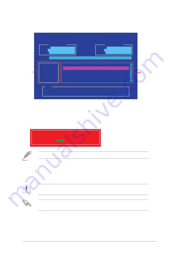
On the BIOS Updater screen, press <Tab> to switch from Files panel to Drives panel 

then select 

D:

ASUSTeK BIOS Updater for DOS V1.30 [2014/01/01]

Current ROM

BOARD:


B85-PRO GAMER

VER:


0212 

(H :00 B :00)

DATE:

 02/12/2014

Update ROM

BOARD:


Unknown

VER:


Unknown

DATE:

 Unknown

PATH:


C:\

C:

D:

FORMAN~1        <DIR>

B85PGM.CAP   8390626  2014-02-10     21:14:34

Note

[Enter] Select or Load    [Tab] Switch   [V] Drive Info

[Up/Down/Home/End] Move   [Esc] Exit

Drives panel

Files panel

3. 

Press <Tab> to switch from Drives panel to Files panel then press <Up/Down or Home/

End> keys to select the BIOS file and press <Enter>.

Summary of Contents for B85-PRO GAMER

Page 1: ...Motherboard B85 PRO GAMER ...

Page 2: ...respective companies and are used only for identification or explanation and to the owners benefit without intent to infringe Offer to Provide Source Code of Certain Software This product contains copyrighted software that is licensed under the General Public License GPL under the Lesser General Public License Version LGPL and or other Free Open Source Software Licenses Such software in this produ...

Page 3: ...nit CPU 1 3 1 4 System memory 1 7 1 5 Expansion slots 1 9 1 6 Jumpers 1 18 1 7 Connectors 1 19 1 8 Onboard LEDs 1 27 1 9 Software support 1 28 BIOS information 2 1 Managing and updating your BIOS 2 1 2 2 BIOS setup program 2 6 2 3 My Favorites 2 9 2 4 Main menu 2 10 2 5 Ai Tweaker menu 2 12 2 6 Advanced menu 2 26 2 7 Monitor menu 2 35 2 8 Boot menu 2 39 2 9 Tool menu 2 45 2 10 Exit menu 2 46 Appen...

Page 4: ...erboard and adding components carefully read all the manuals that came with the package Before using the product ensure all cables are correctly connected and the power cables are not damaged If you detect any damage contact your dealer immediately To avoid short circuits keep paper clips screws and staples away from connectors slots sockets and circuitry Avoid dust humidity and temperature extrem...

Page 5: ...ks properly take note of the following symbols used throughout this manual DANGER WARNING Information to prevent injury to yourself when completing a task CAUTION Information to prevent damage to the components when completing a task IMPORTANT Instructions that you MUST follow to complete a task NOTE Tips and additional information to help you complete a task Typography Bold text Indicates a menu ...

Page 6: ...set limitation DDR3 1600 MHz and higher memory modules on XMP mode will run at the maximum transfer rate of DDR3 1600 MHz Hyper DIMM support is subject to the physical characteristics of individual CPUs Please refer to Memory QVL Qualified Vendors List for details Refer to www asus com for the latest Memory QVL Qualified Vendors List Graphics Integrated graphics processor Intel HD Graphics support...

Page 7: ...ipset 4 x USB3 0 2 0 ports 2 ports at mid board 2 ports at rear panel 8 x USB 2 0 ports 4 ports at mid board 4 ports at rear panel with ASUS USB 3 0 Boost support Rear Panel I O ports 1 x PS 2 keyboard port purple 1 x PS 2 mouse port green 1 x optical S PDIF out 1 x DVI port 1 x HDMI port 1 x D Sub port 1 x LAN RJ 45 port 2 x USB 3 0 2 0 ports 4 x USB 2 0 1 1 ports 8 channel audio I O ports Intern...

Page 8: ... Fan Xpert 2 Fan Auto Tuning function for optimized speed control USB 3 0 Boost Ultra fast USB 3 0 transmission EZ DIY ASUS AI Suite 3 Disk Unlocker AI Charger Award winning BIOS Design ASUS UEFI BIOS EZ Mode featuring friendly graphics user interface ASUS Crashfree BIOS 3 ASUS EZ Flash 2 BIOS features 64 Mb Flash ROM UEFI AMI BIOS PnP DMI v2 0 WfM2 0 SM BIOS v2 7 ACPI v4 0a Multi language BIOS AS...

Page 9: ...ponent ensure that the ATX power supply is switched off or the power cord is detached from the power supply Failure to do so may cause severe damage to the motherboard peripherals or components 1 2 Motherboard overview Before you install the motherboard study the configuration of your chassis to ensure that the motherboard fits Unplug the power cord before installing or removing the motherboard Fa...

Page 10: ...1 2 Chapter 1 Product introduction Place this side towards the rear of the chassis 1 2 3 Motherboard layout ...

Page 11: ...CHA_FAN1 CHA_FAN2 CHA_FAN3 1 21 4 DDR3 DIMM slots 1 7 5 USB 3 0 connector 20 1 pin USB3_12 1 24 6 Intel B85 Serial ATA 6 0 Gb s connector 7 pin SATA6G_1 SATA6G_2 SATA6G_3 SATA6G_4 gray 1 25 7 Intel B85 Serial ATA 3 0 Gb s connectors 7 pin SATA3G_5 SATA3G_6 black 1 25 8 Standby Power LED SB_PWR 1 27 9 System panel connector 20 8 pin F_PANEL 1 26 10 USB 2 0 connectors 10 1 pin USB1314 USB34 1 24 11 ...

Page 12: ...are not bent Contact your retailer immediately if the PnP cap is missing or if you see any damage to the PnP cap socket contacts motherboard components ASUS will shoulder the cost of repair only if the damage is shipment transit related Keep the cap after installing the motherboard ASUS will process Return Merchandise Authorization RMA requests only if the motherboard comes with the cap on the LGA...

Page 13: ...ASUS B85 PRO GAMER 1 5 A B C 5 4 1 3 2 CPU heatsink and fan assembly installation Apply the Thermal Interface Material to the CPU heatsink and CPU before you install the heatsink and fan if necessary ...

Page 14: ...1 6 Chapter 1 Product introduction 3 4 A B B A To uninstall the CPU heatsink and fan assembly 2 1 To install the CPU heatsink and fan assembly 2 B A A B 1 ...

Page 15: ...the higher sized channel is then mapped for single channel operation Due to Intel chipset limitation DDR3 1600 MHz and higher memory modules on XMP mode will run at the maximum transfer rate of DDR3 1600 MHz Always install DIMMs with the same CAS latency For optimal compatibility we recommend that you install memory modules of the same version or date code D C from the same vendor Check with the r...

Page 16: ...tem components Failure to do so can cause severe damage to both the motherboard and the components 1 Press the retaining clip outward to unlock a DIMM socket 2 Align a DIMM on the socket such that the notch on the DIMM matches the DIMM slot key on the socket A DIMM is keyed with a notch so that it fits in only one direction DO NOT force a DIMM into a socket in the wrong direction to avoid damaging...

Page 17: ...GX3M2A2133C9 Ver4 21 XMP 16GB 2x 8GB DS 9 11 11 31 1 65 CORSAIR CMD32GX3M4A2133C9 Ver4 21 XMP 32GB 4x 8GB DS 9 11 11 31 1 65 CORSAIR CMD8GX3M2A2133C9 Ver1 5 XMP 8GB 2x 4GB DS 9 11 10 27 1 5 CORSAIR CMD8GX3M2B2133C9 Ver5 12 XMP 8GB 2x 4GB DS 9 11 11 31 1 65 CORSAIR CMY8GX3M2A2133C11R Ver4 21 XMP 8GB 2x 4GB DS 11 11 11 27 1 5 CORSAIR CMZ8GX3M2A2133C11R Ver4 21 XMP 8GB 2x 4GB DS 11 11 11 27 1 5 G SKI...

Page 18: ...3M2A1866C10 Ver5 29 XMP 16GB 2x 8GB DS 10 11 10 30 1 5 CORSAIR CMZ16GX3M2A1866C9 XMP 16GB 2x 8GB DS 1866 9 10 9 27 1 5 CORSAIR CMZ32GX3M4X1866C10 Ver3 23 XMP 32GB 4x 8GB DS 10 11 10 27 1 5 CORSAIR CMZ32GX3M4X1866C10 Ver3 23 XMP 32GB 4x 8GB DS 10 11 10 27 1 5 CORSAIR CMZ8GX3M2A1866C9 Ver8 16 XMP 8GB 2x 4GB DS 9 10 9 27 1 5 CORSAIR CMZ8GX3M2A1866C9 XMP 8GB 2x 4GB DS 9 10 9 27 1 5 CORSAIR CMZ8GX3M2A1...

Page 19: ...t 302G08 GJ1C 9 9 9 27 Asint SLA302G08 EGN1C 4GB DS ASint 302G08 GN1C Asint SLA304G08 ENG1B 4GB SS Asint 304G08 GN1B 9 11 11 28 Asint SLB304G08 EGJ1B XMP 8GB DS 9 9 9 27 Asint SLB304G08 EGN1B 8GB DS ASint 304G08 GN1B Asint SLZ302G08 EGN1C 2GB SS ASint 302G08 GN1C AVEXIR AVD3U16000904G 2CW XMP 8GB 2x 4GB DS 11 11 11 28 1 5 CORSAIR CMD16GX3M2A1600C9 Ver8 21 XMP 16GB 2x 8GB DS 9 9 9 24 1 5 CORSAIR CM...

Page 20: ...X FLGE85F C8KL9A XMP 2GB SS KINGMAX N A 9 9 9 28 KINGMAX FLGF65F C8KL9A XMP 4GB DS KINGMAX N A 9 9 9 28 KINGSTON KHX16009CD3K2 8GX XMP 8GB 2x 4GB DS 9 9 9 27 1 65 KINGSTON KHX1600C9D3B1 4G XMP 4GB SS 9 9 9 27 1 65 KINGSTON KHX1600C9D3K3 12GX XMP 12GB 3x 4GB DS 9 1 65 KINGSTON KHX1600C9D3K3 6GX XMP 6GB 3x 2GB DS 9 1 65 KINGSTON KHX1600C9D3K3 6GX XMP 6GB 3x 2GB DS 9 1 65 KINGSTON KHX1600C9D3K4 16GX ...

Page 21: ...9 24 1 5 Team TLD38G1600HC9BK XMP 16GB 2x 8GB DS 9 9 9 24 1 5 Team TXD34096M1600HC9 D XMP 4GB DS Hynix H5TC2G83BFRH9A 9 9 9 24 1 5 Transcend TS1GLK64V6H 620945 8GB DS SAMSUNG K4B4G0846B Transcend TS1GLK64W6H 8GB DS SAMSUNG K4B4G0846B 11 11 11 28 1 Transcend TS512MLK64W6H 4GB SS SAMSUNG K4B4G0846B 11 11 11 28 2 UMAX 84E44G93UM 16BPSYW 4GB SS UMAX U2S96D30TP 16 1600 11 11 11 28 UMAX 84E48G93UM 16BPS...

Page 22: ...4G1333C9A 4GB 2x 2GB DS 9 9 9 24 1 5 EK Memory EKM324L28BP8 I13 4GB 2x 2GB DS 9 G SKILL F3 10600CL9D 4GBNT 4GB 2x 2GB DS G SKILL D3 128M8CE9 2GB 9 9 9 24 1 5 G SKILL F3 10666CL9D 8GBRL 8GB 2x 4GB DS 9 9 9 24 1 5 G SKILL F3 10666CL9D 8GBRL 8GB 2x 4GB DS 9 9 9 24 1 5 G SKILL F3 10666CL9D 8GBXL 8GB 2x 4GB DS 9 9 9 24 1 5 GEIL GB34GB1333C7DC 4GB 2x 2GB DS GEIL GL1L128M88BA15FW 7 7 7 24 1 5 GEIL GET316...

Page 23: ... DS Mach Xtreme MXD3V13332GS 2GB SS Mach Xtreme C2S46D30 D313 MICRON MT8JTF25664AZ 1G4M1 2GB SS MICRON D9PFJ OCZ OCZ3G1333LV4GK 4GB 2x 2GB DS 9 9 9 1 65 OCZ OCZ3G1333LV8GK 8GB 2x 4GB DS 9 9 9 1 65 OCZ OCZ3G1333LV8GK 8GB 2x 4GB DS 9 9 9 1 65 OCZ OCZ3RPR1333C9LV8GK 8GB 2x 4GB DS 9 9 9 1 65 Patriot PG38G1333EL XMP 8GB DS 1 5 Patriot PGD316G1333ELK XMP 16GB 2x 8GB DS 9 9 9 24 1 5 Patriot PGS34G1333LLK...

Page 24: ... expansion card After installing the expansion card configure it by adjusting the software settings 1 Turn on the system and change the necessary BIOS settings if any See Chapter 2 for information on BIOS setup 2 Assign an IRQ to the card 3 Install the software drivers for the expansion card When using PCI cards on shared slots ensure that the drivers support Share IRQ or that the cards do not nee...

Page 25: ... 5 PCI Express 3 0 2 0 x16 slots This motherboard supports PCI Express x16 network cards SCSI cards and other cards that comply with the PCI Express specifications IRQ assignments for this motherboard A B C D E F G H I G D Shared HD Audio 1 Controller Shared HD Audio 2 Controller Shared EHCI 1 Controller Shared EHCI 2 Controller Shared XHCI Controller Shared SATA Controller Shared PCIE x16_1 Share...

Page 26: ... 10 seconds then move the cap back to pins 1 2 3 Plug the power cord and turn ON the computer If the steps above do not help remove the onboard battery and move the jumper again to clear the CMOS RTC RAM data After clearing the CMOS reinstall the battery You do not need to clear the RTC when the system hangs due to overclocking For system failure due to overclocking use the CPU Parameter Recall C ...

Page 27: ...r other VGA compatible devices 4 USB 2 0 ports 1 2 3 and 4 These two 4 pin Universal Serial Bus USB ports are for USB 2 0 1 1 devices 5 LAN RJ 45 port This port allows Gigabit connection to a Local Area Network LAN through a network hub LAN port LED indications Activity Link LED Speed LED Status Description Status Description Off No link OFF 10 Mbps connection Orange Linked ORANGE 100 Mbps connect...

Page 28: ...el Clock H total x V Total x Frame Rate Screen refresh rate DVI port 165 MHz VGA port 180 MHz HDMI port 300 MHz 6 PS 2 keyboard port purple This port is for a PS 2 keyboard 7 HDMI port This port connects to the tape CD DVD player or other audio sources 8 DVI D port This port is for any DVI D compatible device DVI D can not be converted to output from RGB Signal to CRT and is not compatible with DV...

Page 29: ...ctors 4 pin CPU_FAN 4 pin CPU_OPT CHA_FAN1 CHA_FAN2 CHA_FAN3 Connect the fan cables to the fan connectors on the motherboard ensuring that the black wire of each cable matches the ground pin of the connector Do not forget to connect the fan cables to the fan connectors Insufficient air flow inside the system may damage the motherboard components These are not jumpers Do not place jumper caps on th...

Page 30: ...you are uncertain about the minimum power supply requirement for your system refer to the Recommended Power Supply Wattage Calculator at http support asus com PowerSupplyCalculator PSCalculator aspx SLanguage en us for details 3 ATX power connectors 24 pin EATXPWR 8 pin EATX12V These connectors are for ATX power supply plugs The power supply plugs are designed to fit these connectors in only one o...

Page 31: ... If you want to connect a high definition front panel audio module to this connector set the Front Panel Type item in the BIOS setup to HD If you want to connect an AC 97 front panel audio module to this connector set the item to AC97 By default this connector is set to HD See section 2 6 7 Onboard Devices Configuration for details 6 Digital audio connector 4 1 pin SPDIF_OUT This connector is for ...

Page 32: ...ever connect a 1394 cable to the USB connectors Doing so will damage the motherboard The USB 2 0 module is purchased separately 7 USB 3 0 connector 20 1 pin USB3_12 This connector allows you to connect a USB 3 0 module for additional USB 3 0 front or rear panel ports With an installed USB 3 0 module you can enjoy all the benefits of USB 3 0 including faster data transfer speeds of up to 5 Gbps fas...

Page 33: ... plug and NCQ set the SATA Mode Selection item in the BIOS to AHCI See section SATA Configuration for details 10 Intel B85 Serial ATA 3 0 Gb s connectors 7 pin SATA3G_5 SATA3G_6 black These connectors connect to Serial ATA 3 0 Gb s hard disk drives and optical drives via Serial ATA 3 0 Gb s signal cables When using hot plug and NCQ set the SATA Mode Selection item in the BIOS to AHCI See section S...

Page 34: ...ng speaker 4 pin SPEAKER This 4 pin connector is for the chassis mounted system warning speaker The speaker allows you to hear system beeps and warnings ATX power button soft off button 2 pin PWR_SW This connector is for the system power button Pressing the power button turns the system on or puts the system in sleep or soft off mode depending on the operating system settings Pressing the power sw...

Page 35: ...tandby power LED that lights up to indicate that the system is ON in sleep mode or in soft off mode This is a reminder that you should shut down the system and unplug the power cable before removing or plugging in any motherboard component The illustration below shows the location of the onboard LED ...

Page 36: ...vail all motherboard features The contents of the Support DVD are subject to change at any time without notice Visit the ASUS website at www asus com for updates The following screen is for reference only To run the Support DVD Place the Support DVD into the optical drive If Autorun is enabled in your computer the DVD automatically displays the lists of the unique features of your ASUS motherboard...

Page 37: ...Restores the BIOS using the motherboard support DVD or a USB flash drive when the BIOS file fails or gets corrupted 4 ASUS BIOS Updater Updates the BIOS in DOS environment using the motherboard support DVD and a USB flash disk drive Save a copy of the original motherboard BIOS file to a USB flash disk in case you need to restore the BIOS in the future Copy the original motherboard BIOS using the A...

Page 38: ...3 Press Tab to switch to the Drive field 4 Press the Up Down arrow keys to find the USB flash disk that contains the latest BIOS then press Enter 5 Press Tab to switch to the Folder Info field 6 Press the Up Down arrow keys to find the BIOS file then press Enter to perform the BIOS update process 7 Reboot the system when the update process is done This function supports USB flash disks formatted u...

Page 39: ...en found the utility reads the BIOS file and automatically enters ASUS EZ Flash 2 utility The system requires you to enter BIOS Setup to recover BIOS settings DO NOT shut down or reset the system while updating the BIOS Doing so can cause system boot failure 3 Press F5 to load default BIOS values Highly recommended 2 1 4 ASUS BIOS Updater ASUS BIOS Updater allows you to update the BIOS in DOS envi...

Page 40: ...3824MB Enter Setup and to move selection ENTER to select boot device ESC to boot using defaults 4 When the Boot Loader appears press Enter within five 5 seconds to enter FreeDOS prompt Updating the BIOS file To update the BIOS file 1 On the FreeDOS prompt type bupdater pc g and press Enter Welcome to FreeDOS http www freedos org C d D D bupdater pc g 5 On the FreeDOS prompt type d then press Enter...

Page 41: ...pdate Are you sure you want to update the BIOS Yes No The BIOS Backup feature is not supported due to security regulations 2 On the BIOS Updater screen press Tab to switch from Files panel to Drives panel then select D ASUSTeK BIOS Updater for DOS V1 30 2014 01 01 Current ROM BOARD B85 PRO GAMER VER 0212 H 00 B 00 DATE 02 12 2014 Update ROM BOARD Unknown VER Unknown DATE Unknown PATH C C D FORMAN ...

Page 42: ...s shut down the system properly from the operating system The BIOS setup screens shown in this section are for reference only Some screen displays may not be the same as what you see on your screen Visit the ASUS website at www asus com to download the latest BIOS file for this motherboard Ensure that a USB mouse is connected to your motherboard if you want to use the mouse to control the BIOS set...

Page 43: ...ys the Advanced mode menus Selects the Advanced mode functions Power saving mode EZ Mode By default the EZ Mode screen appears when you enter the BIOS setup program The EZ Mode provides you an overview of the basic system information and allows you to select the display language system performance mode and boot device priority To access the Advanced Mode click Exit Advanced Mode then select Advanc...

Page 44: ...ptions and loading default settings Menu items The highlighted item on the menu bar displays the specific items for that menu For example selecting Main shows the Main menu items The other items Ai Tweaker Advanced Monitor Boot Tool and Exit on the menu bar have their respective menu items Back button This button appears when entering a submenu Press Esc or use the USB mouse to click this button t...

Page 45: ...al help At the top right corner of the menu screen is a brief description of the selected item Configuration fields These fields show the values for the menu items If an item is user configurable you can change the value of the field opposite the item You cannot select an item that is not user configurable A configurable field is highlighted when selected To change the value of a field select it a...

Page 46: ...o set the system date 2 4 3 System Time xx xx xx Allows you to set the system time 2 4 4 Security The Security menu items allow you to change the system security settings Adding items to My Favorites To add frequently used BIOS items to My Favorites 1 Use the arrow keys to select an item that you want to add When using a mouse hover the pointer to the item 2 Press F4 on your keyboard or right clic...

Page 47: ...d box key in the current password then press Enter 3 From the Create New Password box key in a new password then press Enter 4 Confirm the password when prompted To clear the administrator password follow the same steps as in changing an administrator password but press Enter when prompted to create confirm the password After you clear the password the Administrator Password item on top of the scr...

Page 48: ...ause the system to malfunction The configuration options for this section vary depending on the CPU and DIMM model you installed on the motherboard Scroll down to display the following items To clear the user password follow the same steps as in changing a user password but press Enter when prompted to create confirm the password After you clear the password the User Password item on top of the sc...

Page 49: ...y Auto Loads the optimal settings for the system X M P If you install memory modules supporting the eXtreme Memory Profile X M P Technology choose this item to set the profiles supported by your memory modules for optimizing the system performance 2 5 2 CPU Core Ratio Auto Allows you to set the CPU core ratio automatically or manually Auto Sets all CPU Core Ratio to Intel CPU default settings auto...

Page 50: ...e BCLK and DRAM frequency Auto The Ratio will be set to the optimized settings 100 133 The Ratio will be set to 100 133 100 100 The Ratio will be set to 100 100 2 5 6 DRAM Frequency Auto Allows you to set the memory operating frequency The configuration options vary with the BCLK Frequency item settings Selecting a very high frequency may cause the system to become unstable If this happens revert ...

Page 51: ... CAS Delay Auto Configuration options Auto 1 DRAM Clock 31 DRAM Clock DRAM RAS PRE Time Auto Configuration options Auto 1 DRAM Clock 31 DRAM Clock DRAM RAS ACT Time Auto Configuration options Auto 1 DRAM Clock 63 DRAM Clock DRAM Command Rate Auto Configuration options Auto 1 DRAM Clock 2 DRAM Clock Secondary Timings DRAM RAS to RAS Delay Auto Configuration options Auto 1 DRAM Clock 15 DRAM Clock D...

Page 52: ...3 DRAM RTL CHA_R1D0 Auto Configuration options Auto 1 63 DRAM RTL CHA_R1D1 Auto Configuration options Auto 1 63 DRAM RTL CHB_R0D0 Auto Configuration options Auto 1 63 DRAM RTL CHB_R0D1 Auto Configuration options Auto 1 63 DRAM RTL CHB_R1D0 Auto Configuration options Auto 1 63 DRAM RTL CHB_R1D1 Auto Configuration options Auto 1 63 DRAM IO L CHA_R0D0 Auto Configuration options Auto 1 15 DRAM IO L CH...

Page 53: ...ation options Auto 1 DRAM Clock 63 DRAM Clock tWRRD_dr Auto Configuration options Auto 1 DRAM Clock 15 DRAM Clock tWRRD_dd Auto Configuration options Auto 1 DRAM Clock 15 DRAM Clock tWRWR Auto Configuration options Auto 1 DRAM Clock 7 DRAM Clock tWRWR_dr Auto Configuration options Auto 1 DRAM Clock 15 DRAM Clock tWRWR_dd Auto Configuration options Auto 1 DRAM Clock 15 DRAM Clock Dec_WRD Auto Confi...

Page 54: ...just these items may enhance the DRAM overclocking capability and stability Transmitter Rising Slope Auto Configuration options 0 31 Transmitter Fallng Slope Auto Configuration options 0 31 Transmitter Control Time Auto Configuration options 0 31 Receiver Rising Slope Auto Configuration options 0 31 Receiver Fallng Slope Auto Configuration options 0 31 Receiver Control Time Auto Configuration opti...

Page 55: ...tage Frequency item to Auto and allows you to enable the spread spectrum to enhance system stability CPU Power Phase Control Auto Allows you to set the power phase based on the CPU Configuration options Auto Standard Optimized Extreme DO NOT remove the thermal module when setting this item to Extreme The thermal conditions should be monitored CPU Power Duty Control T Probe DIGI VRM Duty Control ad...

Page 56: ... Mode Parameters Long Duration Package Power Limit Auto Allows you to limit the turbo ratio s long duration package power Package Power Time Window Auto Allows you to set the package power time window Use the and keys to adjust the value Short Duration Package Power Limit Auto Allows you to limit the turbo ratio s long duration power Use the and keys to adjust the value CPU Integrated VR Current L...

Page 57: ...to Allows you to set the power current slope Configuration options Auto Level 4 Level 3 Level 2 Level 1 Level 0 Level 1 Level 2 Level 3 Level 4 Power Current Offset Auto Allows you to set the power current offset Configuration options Auto 100 87 5 75 62 5 50 37 5 25 12 5 0 12 5 25 37 5 50 0 62 5 75 87 5 100 Power Fast Ramp Response Auto Allows you to set the power fast ramp response Use the and k...

Page 58: ...n options CPU Core Voltage Offset Auto This item appears only when you set the CPU Core Voltage to Offset Mode and allows you to set the CPU core voltage offset The values range from 0 001V to 0 999V with a 0 001V interval The following two items appear only when you set the CPU Core Voltage to Offset Mode Offset Mode Sign This item appears only when you set the CPU Core Voltage to Offset Mode and...

Page 59: ...values range from 0 001V to 1 920V with a 0 001V interval Offset Mode Sign This item appears only when you set the CPU Graphics Voltage to Offset Mode or Adaptive Mode and allows you to set the offset mode sign Configuration options CPU Graphics Voltage Offset Auto This item appears only when you set the CPU Graphics Voltage to Offset Mode or Adaptive Mode and allows you to set the CPU graphics vo...

Page 60: ...y The values range from 0 001V to 0 999V with a 0 001V interval 2 5 19 CPU Digital I O Voltage Offset Mode Sign This item allows you to set the CPU digital I O voltage offset mode sign Configuration options CPU Digital I O Voltage Offset Auto This item allows you to set the CPU digital I O voltage offset Increase the value when increasing DRAM frequency The values range from 0 001V to 0 999V with ...

Page 61: ...stem to work stably under high voltage settings 2 5 24 PCH VLX Voltage Auto Allows you to set the voltage for the I O on the PCH Use the or keys to adjust the value The values range from 1 2V to 2 0V with a 0 0125V interval 2 5 25 DRAM CTRL REF Voltage Auto Allows you to set the DRAM CTRL REF Voltage The values range from 0 3950x to 0 6300x with a 0 0050x interval 2 5 26 DRAM DATA REF Voltage on C...

Page 62: ...ly Enabled Two threads per activated core are enabled Disabled Only one thread per activated core is enabled Active Processor Cores All Allows you to choose the number of CPU cores to activate in each processor package Configuration options All 1 2 3 Limit CPUID Maximum Disabled Enabled Allows legacy operating systems to boot even without support for CPUs with extended CPUID functions Disabled Dis...

Page 63: ...ormance mode Max Non Tu This item allows you to select the boot performance mode Configuration options Max Non Turbo Performance Max battery Turbo Performance CPU Power Management Configuration This item allows you to manage and configure the CPU s power EIST Enabled Allows you to enable or disable the Enhanced Intel SpeedStep Technology EIST Disabled The CPU runs at its default speed Enabled The ...

Page 64: ...nfiguration options Auto Enabled C0 C1 C2 C3 C6 CPU C7 CPU C7s 2 6 2 PCH Configuration PCI Express Configuration DMI Link ASPM Control Auto Allows you to control the Active State Power Managemennt on both NB and SB side of the DMI Link Configuration options Auto Enabled Disabled ASPM Support Disabled Allows you to set the ASPM support Configuration options Disabled Auto L0s L1 L0sL1 PCIe Speed Aut...

Page 65: ...BIOS automatically detects the presence of SATA devices The SATA Port items show Not Present if no SATA device is installed to the corresponding SATA port SATA Mode Selection AHCI Allows you to set the SATA configuration Disabled Disables the SATA function IDE Set to IDE when you want to use the Serial ATA hard disk drives as Parallel ATA physical storage devices AHCI Set to AHCI when you want the...

Page 66: ...28M 160M 192M 224M 256M 288M 320M 352M 384M 416M 448M 480M 512M 1024M Render Standby Auto Allows you to enable or disable Intel Graphics Render Standby support to reduce iGPU power use when the system is idle Configuration options Auto Disabled Enabled iGPU Multi Monitor Disabled Allows you to enable the iGPU Multi Monitor For LucidLogix Virtu MVP function support set this item to Enabled to empow...

Page 67: ...vice at present Configuration options Disabled Auto ASPM L0s ASPM L1 ASPM L0sL1 Memory Configuration Memory Scrambler Enabled Allows you to enable or disable Memory Scrambler support Memory Remap Enabled Allows you to enable or disable remapping the memory above 4GB Enabled Enables the function Disabled Disables this function 2 6 5 USB Configuration The items in this menu allow you to change the U...

Page 68: ...he power saving feature of PCI Express and perform ASPM operations in the operating system Configuration options Disabled Enabled Native ASPM Disabled The item appears only when you set the PCI Express Native Power Management to Enabled and allows you to enable or disable ASPM Configuration options Enabled Disabled 2 6 7 Onboard Devices Configuration HD Audio Controller Enabled Enabled Enables the...

Page 69: ...select the Serial Port base address Configuration options IO 3F8h IRQ 4 IO 2F8h IRQ 3 IO 3E8h IRQ 4 IO 2E8h IRQ 3 2 6 8 APM ErP Ready Disabled Allows you to switch off some power at S4 S5 or S5 to get the system ready for ErP requirement When set to Enabled all other PME options will be switched off Configuration options Disabled Enabled S4 S5 Enabled S5 Restore AC Power Loss Power Off Power On Th...

Page 70: ...nabled Enables Ring to generate a wake event Power On By RTC Disabled Disabled Disables RTC to generate a wake event Enabled When set to Enabled the items RTC Alarm Date Days and Hour Minute Second will become user configurable with set values 2 6 9 Network Stack Configuration Network Stack Disabled This item allows user to disable or enable the UEFI network stack Configuration options Disabled En...

Page 71: ...ASUS B85 PRO GAMER 2 35 2 7 Monitor menu The Monitor menu displays the system temperature power status and allows you to change the fan settings Scroll down to display the following items ...

Page 72: ...tage 12V Voltage The onboard hardware monitor automatically detects the voltage output through the onboard voltage regulators Select Ignore if you do not want to detect this item 2 7 5 CPU Q Fan Control Auto Disabled Disables the CPU Q Fan control feature Auto Enables the CPU Q Fan control for 4 pin CPU fan Advance Mode Select this mode for the DC mode Q Fan control when a 3 pin CPU fan is install...

Page 73: ...sis Fan 3 Q Fan Control Enabled Disabled Disables the Chassis fan 1 2 3 4 Q Fan control feature Enabled Enables the Chassis fan 1 2 3 4 Q Fan control feature Chassis Fan 1 Chassis Fan 2 Chassis Fan 3 Speed Low Limit 600 RPM This item appears only when you enable the Chassis Fan Q Fan Control feature and allows you to disable or set the chassis fan warning speed Configuration options Ignore 200RPM ...

Page 74: ...om 60 to 100 When the chassis temperature reaches the upper limit the chassis fan 1 2 3 4 will operate at the maximum duty cycle Chassis Fan 1 2 3 Lower Temperature 40 Displays the lower limit of the chassis temperature CHASSIS Fan 1 2 3 Min Duty Cycle 60 Use the and keys to adjust the minimum chassis fan duty cycle The values range from 60 to 100 When the chassis temperature is under 40 C the cha...

Page 75: ...following four items appear when you set Fast Boot to Enabled SATA Support All Devices All Devices All devices connected to SATA ports will be available during POST This process will extend the POST time Hard Drive Only Only hard drives connected to SATA ports will be detected during POST Any hardware change will disable fast boot Boot Drive Only Only boot drive connected to SATA ports will be det...

Page 76: ...ances This process will extend POST time Disabled For the fastest POST time all PS 2 devices will not be available until your computer enters the operating system Network Stack Driver Support Disabled Disabled Select to skip the network stack driver from loading during POST Enabled Select to load the network stack driver during POST Next Boot after AC Power Loss Normal Boot Normal Boot Returns to ...

Page 77: ...abled Enabled Allows the option ROMs to trap Interrupt 19 Disabled Disables this function 2 8 8 Setup Mode EZ Mode Advanced Mode Sets Advanced Mode as the default screen for entering the BIOS setup program EZ Mode Sets EZ Mode as the default screen for entering the BIOS setup program 2 8 9 CSM Compatibility Support Module Allows you to configure the CSM Compatibility Support Module items to fully ...

Page 78: ...ystem from unauthorized access and malwares during POST OS Type Windows UE Allows you to select your installed operating system Windows UEFI mode Executes the Microsoft Secure Boot check Only select this option when booting on Windows UEFI mode or other Microsoft Secure Boot compliant OS Other OS Get the optimized function when booting on Windows non UEFI mode Windows Vista XP or other Microsoft S...

Page 79: ...ot Key Enrollment Key KEK Delete the KEK Allows you to delete the KEK from your system Configuration options Yes No Load KEK from File Allows you to load the downloaded KEK from a USB storage device Append KEK from file Allows you to load the additional KEK from a storage device for an additional db and dbx loaded management The KEK file must be formatted as a UEFI variable structure with time bas...

Page 80: ...icated variable 2 8 11 Boot Option Priorities These items specify the boot device priority sequence from the available devices The number of device items that appears on the screen depends on the number of devices installed in the system To select the boot device during system startup press F8 when ASUS Logo appears To access Windows OS in Safe Mode do any of the following Press F5 when ASUS Logo ...

Page 81: ...rofile Name Allows you to key in a profile name Save to Profile Allows you to save the current BIOS settings to the BIOS Flash and create a profile Key in a profile number from one to eight press Enter and then select Yes Load Profile Allows you to load the previous BIOS settings saved in the BIOS Flash Key in the profile number that saved your CMOS settings press Enter and then select Yes DO NOT ...

Page 82: ...F5 a confirmation window appears Select Yes to load the default values Save Changes Reset Once you are finished making your selections choose this option from the Exit menu to ensure the values you selected are saved When you select this option or if you press F10 a confirmation window appears Select Yes to save changes and exit Discard Changes Exit This option allows you to exit the Setup program...

Page 83: ... different from that to which the receiver is connected Consult the dealer or an experienced radio TV technician for help The use of shielded cables for connection of the monitor to the graphics card is required to assure compliance with FCC regulations Changes or modifications to this unit not expressly approved by the party responsible for compliance could void the user s authority to operate th...

Page 84: ...out wheeled bin indicates that the battery should not be placed in municipal waste ASUS Recycling Takeback Services ASUS recycling and takeback programs come from our commitment to the highest standards for protecting our environment We believe in providing solutions for you to be able to responsibly recycle our products batteries other components as well as the packaging materials Please go to ht...

Page 85: ...xt 9101 Online support http support asus com techserv techserv aspx ASUS COMPUTER INTERNATIONAL America Address 800 Corporate Way Fremont CA 94539 USA Telephone 1 510 739 3777 Fax 1 510 608 4555 Web site http usa asus com Technical Support Support fax 1 812 284 0883 General support 1 812 282 2787 Online support http support asus com techserv techserv aspx ASUS COMPUTER GmbH Germany and Austria Add...

Page 86: ...name B85 PRO GAMER conform with the essential requirements of the following directives 2004 108 EC EMC Directive EN 55022 2010 AC 2011 EN 61000 3 2 2006 A2 2009 EN 55013 2001 A1 2003 A2 2006 EN 55024 2010 EN 61000 3 3 2008 EN 55020 2007 A11 2011 1999 5 EC R TTE Directive EN 300 328 V1 7 1 2006 10 EN 300 440 1 V1 6 1 2010 08 EN 300 440 2 V1 4 1 2010 08 EN 301 511 V9 0 2 2003 03 EN 301 908 1 V5 2 1 ...

Reviews: