background image


Chapter 3 

 Gateway Setup and Configuration 


14


IO

T G

at

eway 
Sy

ste

m


SPG

-M0
41


3.1.1 

Serial Connection 


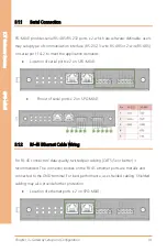
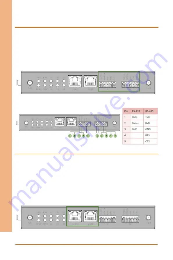
PG-M041 provides serial RS-485/RS-232 ports x 2, which are software-definable, users 

may setup type of communication interface (RS-232, 3-wire RS-485 or 2-wire RS-485) 

on serial port 1 & 2 to meet the application demands. 


Location of serial ports x 2 on SPG-M041: 


Pinout of serial ports x 2 on SPG-M041: 


3.1.2 

RJ-45 Ethernet Cable Wiring 


For RJ-

45 connectors’ data

-quality, twisted pair cabling (CAT5/5e or better) is 

recommended. The connector bodies on the RJ-45 ethernet ports are metallic and 

connected to the GND terminal. For best performance, use shielded cabling. Shielded 

cabling may also provide further protection. 


Location of ethernet ports x 2 on SPG-M041: 


Summary of Contents for AAEON SPG-M041

Page 1: ...Last Updated July 4 2022 IOT Gateway System SPG M041 SPG M041 IoT Gateway System User s Manual 1st Ed ...

Page 2: ...in this manual is intended to be accurate and reliable However the original manufacturer assumes no responsibility for its use or for any infringements upon the rights of third parties that may result from its use The material in this document is for product information only and is subject to change without notice While reasonable efforts have been made in the preparation of this document to assur...

Page 3: ...Cortex and Cortex A8 are registered trademarks of Arm Limited or its subsidiaries ITE is a trademark of Integrated Technology Express Inc IBM and VGA are trademarks of International Business Machines Corporation Ubuntu is a registered trademark of Canonical All other product names or trademarks are properties of their respective owners No ownership is implied or assumed for products names or trade...

Page 4: ...1 Packing List Before setting up your product please make sure the following items have been shipped Item Quantity SPG M041 1 If any of these items are missing or damaged please contact your distributor or sales representative immediately ...

Page 5: ... descriptions and explanations on the product s hardware and software features if any its specifications dimensions jumper connector settings definitions and driver installation instructions if any to facilitate users in setting up their product Users may refer to the product page at AAEON com for the latest version of this document ...

Page 6: ... system s hardware 6 No connections should be made when the system is powered as a sudden rush of power may damage sensitive electronic components 7 If the device is not to be used for a long time disconnect it from the power supply to avoid damage by transient over voltage 8 Always disconnect this device from any AC supply before cleaning 9 While cleaning use a damp cloth instead of liquid or spr...

Page 7: ...rs 18 If any of the following situations arises please the contact our service personnel i Damaged power cord or plug ii Liquid intrusion to the device iii Exposure to moisture iv Device is not working as expected or in a manner as described in this manual v The device is dropped or damaged vi Any obvious signs of damage displayed on the device 19 DO NOT LEAVE THIS DEVICE IN AN UNCONTROLLED ENVIRO...

Page 8: ...losion if the battery is incorrectly replaced Replace only with the same or equivalent type recommended by the manufacturer Dispose of used batteries according to the manufacturer s instructions and your local government s recycling or disposal directives Attention Il y a un risque d explosion si la batterie est remplacée de façon incorrecte Ne la remplacer qu avec le même modèle ou équivalent rec...

Page 9: ... 铅 Pb 汞 Hg 镉 Cd 六价铬 Cr VI 多溴联苯 PBB 多溴二苯 醚 PBDE 印刷电路板 及其电子组件 外部信号 连接器及线材 外壳 中央处理器 与内存 硬盘 液晶模块 光驱 触控模块 电源 电池 本表格依据 SJ T 11364 的规定编制 表示该有毒有害物质在该部件所有均质材料中的含量均在 GB T 26572标准规定的限量要求以下 表示该有害物质的某一均质材料超出了GB T 26572的限量要求 然而该 部件 仍符合欧盟指令2011 65 EU 的规范 备注 一 此产品所标示之环保使用期限 系指在一般正常使用状况下 二 上述部件物质中央处理器 内存 硬盘 光驱 电源为选购品 三 上述部件物质液晶模块 触控模块仅一体机产品适用 ...

Page 10: ...PSU X O O O O O Battery X O O O O O This form is prepared in compliance with the provisions of SJ T 11364 O The level of toxic or hazardous materials present in this component and its parts is below the limit specified by GB T 26572 X The level of toxic of hazardous materials present in the component exceed the limits specified by GB T 26572 but is still in compliance with EU Directive 2011 65 EU ...

Page 11: ...ay Setup and Configuration 12 3 1 System Test and Initialization 13 3 1 1 Serial Connection 14 3 1 2 RJ 45 Ethernet Cable Wiring 14 3 1 3 Digital Input DI Connection 16 3 1 4 Relay Output Connection 17 3 1 5 WWAN Module Installation 18 3 1 6 SIM Installation 19 3 1 7 MicroSD Card Installation Without Cover 20 3 2 Connecting Power Supply 21 3 3 Reset Button 23 3 4 Installation and Mounting 24 3 4 1...

Page 12: ...IOT Gateway System SPG M041 Chapter 1 Chapter 1 Product Specifications ...

Page 13: ...r serial port DI RF activity signal strength indicators Real time clock Yes Expansion Mini PCIe slot x 1 UART signal for wireless module Nano SIM card slot x 2 Micro SD card slot x 1 Radio Frequency LTE 4G CAT 1 by model 3GPP Rel 9 compliant protocol Frequency bands FDD LTE B1 B2 B3 B4 B5 B7 B8 B12 B13 B18 B19 B20 B25 B26 B28 TDD LTE B38 B39 B40 B41 WCDMA B1 B2 B4 B5 B6 B8 B19 GSM B2 B3 B5 B8 Data...

Page 14: ... model 3GPP Rel 14 compliant protocol Frequency bands FDD LTE B1 B2 B3 B4 B5 B8 B12 B13 B18 B19 B20 B25 B26 B27 B28 B66 B71 B85 GSM 850MhZ 900Mhz 1800Mhz 1900Mhz Data rate LTE Cat NB1 DL max 27 kbps UL max 63 kbps LTE Cat NB2 DL max 124 kbps UL max 158 kbps LTE Cat M1 DL max 300 kbps UL max 1 1 Mbps SIM Card type Micro SIM slot Antenna Type External type Antenna Connector SMA Male GPS GPS GLONASS ...

Page 15: ...Rate 300 921 6kbps Data Bits 7 8 Parity Odd Even None Stop bits 1 2 RS 232 Pinout TxD RxD RTC CTS GND RS 485 Pinout 3 Wire Data Data GND 2 Wire Data Data Terminator for RS 485 120 ohms software selectable Magnetic isolation protection Digital Input Digital Terminal Block x 4 Serial Standards RS232 3W RS485 2W RS485 Input Types P switching Input Filter Time Input delay adjustable from 0 to 40ms dis...

Page 16: ...To COM On 10 30 VDC Off 0 3 VDC Reverse Polarity Protection Yes Individual Channel Diagnostic No Magnetic Isolation Protection 1 5 kV Relay Output Relay Output Terminal Block x 1 Output Types Normally open NO Output Delay Output delay adjustable from 0 to 10s no delay 500ms 1s 2s 5s 10s Max Output Current Per Input 1A at 250VAC 1A at 30VDC Actuator Connection 2 wire Individual Channel Diagnostic N...

Page 17: ...e 9 6 31 2 VDC Input Current 12V 2 29W 24V 3 14W Reverse Polarity Protection Yes Voltage Variation Protection Yes Mechanical Enclosure Metallic Casing Dimensions W x D x H 6 2 x 6 2 x 1 0 160mm x 106mm x 27 mm Weight 1 1 lb 0 5 Kg Mounting DIN Rail Mounting Environmental Operating Temperature 4O F 158O F 20O C 70O C Storage Temperature 40O F 185O F 40O C 85O C Operating Humidity 5 95 non condensin...

Page 18: ...Chapter 2 Chapter 2 Hardware Information ...

Page 19: ...Chapter 2 Hardware Information 8 IOT Gateway System SPG M041 2 1 Dimensions ...

Page 20: ...ity for local network or internet access 3 Serial 1 Terminal block RS 232 RS 485 software selectable 4 Serial 2 Terminal block 5 Antenna RP SMA male Antenna for wireless WAN 3G 4G access 6 Antenna Reserved 7 Antenna RP SMA female Antenna for GPS signal reception 8 External storage Micro SD Micro SD storage for system log event message data storage 9 Console Micro USB Interface for device administr...

Page 21: ...er Green Wireless strength 75 Amber Wireless strength 50 75 Amber blinking Wireless strength 25 50 OFF Wireless strength 25 LPWAN Green Amber Operational while second module installed Off System is not working Relay Orange Blinking Ethernet port is transmitting or receiving data Steady on Ethernet capable of 10Mbps or 100Mbps operations Green On 100Mbps Ethernet connection Off 10Mbps Ethernet conn...

Page 22: ...e serial interface DI0 Digital Input Yellow On incoming signal is transmitted to the port Off No signal is sent to the port DI1 Digital Input Orange On incoming signal is transmitted to the port Off No signal is sent to the port DI2 Digital Input Orange On incoming signal is transmitted to the port Off No signal is sent to the port DI3 Digital Input Orange On incoming signal is transmitted to the ...

Page 23: ...Chapter 3 Chapter 3 Gateway Setup and Configuration ...

Page 24: ...can interference with the device s performance Ensure the cabling is positioned away from equipment that can damage the cables In Ethernet 10 100 fixed port devices the cable length from the fieldbus gateway to connected devices cannot exceed 100 meters 328 feet Ensure airflow around the fieldbus gateway and respective vents is unrestricted Without proper airflow the fieldbus gateway can overheat ...

Page 25: ...rt 1 2 to meet the application demands Location of serial ports x 2 on SPG M041 Pinout of serial ports x 2 on SPG M041 3 1 2 RJ 45 Ethernet Cable Wiring For RJ 45 connectors data quality twisted pair cabling CAT5 5e or better is recommended The connector bodies on the RJ 45 ethernet ports are metallic and connected to the GND terminal For best performance use shielded cabling Shielded cabling may ...

Page 26: ...Chapter 3 Gateway Setup and Configuration 15 IOT Gateway System SPG M041 Note Maximum cable length 100 meters 328 ft for 10 100BaseT ...

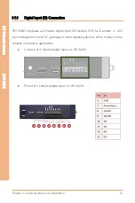
Page 27: ...nection SPG M041 integrates a 4 channel digital input DI module SPG M 41 accepts 4 20V input voltage from most PLC gateway or other signaling devices which makes it more versatile in industrial applications Location of 4 channel digital input on SPG M041 Pinout of 4 channel digital input on SPG M041 ...

Page 28: ...et Contact 3 1 4 Relay Output Connection SPG M041 integrates single channel relay output interface Relay interface on SPG M041 is ideal for low power switching applications such as ON OFF control event trigger and it is safety value setting compliant Location of one channel relay output on SPG M041 Wiring scheme of relay output ...

Page 29: ...osition of WWAN module Install the WWAN module and fix antennas to the reserved antenna holes in the casing WWAN module Mini PCIe WWAN module installation Make sure the IoT gateway is not powered on Make sure the IoT gateway is not powered on Open the case and identify the mPCIe slot on IoT gateway Align the WWAN module card with the mPCIe slot and push the card straight into the mPCIe slot gently...

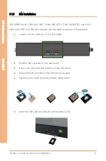
Page 30: ...no SIM 4FF The SIM slot locations are allocated at the rear of the product Location of SIM card slot x 2 on SPG M041 Find the SIM card slot on the rear panel Get a nano SIM card and install it on the SIM carrier Ensure the SIM card fits on the SIM carrier securely Flip the combo with the gold contacts facing down Insert the SIM card into the slot until hearing a click ...

Page 31: ...s supported Note Before Installing a microSD Card it is recommended to format the microSD card to FAT32 to ensure proper file read write access Location of MicroSD Card slot on SPG M041 1 The microSD card has a beveled edge When installing the SD card please make sure the card is aligned with the groove If there is any resistance remove the card and re align it to the slot 2 Insert the microSD car...

Page 32: ...in good condition before using them Do not overload the power points or plugs Make sure the product maintains a proper grounding connection Use a power supply that meets the product requirements and complies with the relevant standards and regulations Connect to power only after the installation of the system has been completed Never connect or disconnect the cables with the system or the external...

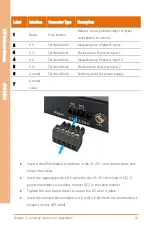
Page 33: ...of power input 2 5 V2 Terminal block Positive pole of power input 2 6 Ground Terminal block Earthing point for power supply 7 Ground screw Insert a small flat bladed screwdriver in the V1 V1 wire clamp screws and loosen the screws Insert the negative positive DC wires into the V1 V1 terminals of DC1 If power redundancy is enabled connect DC2 in the same manner Tighten the wire clamp screws to secu...

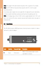
Page 34: ...dundancy to reduce network downtime as well as preventing chaos brought by power loss Note A DC voltage range of 12 to 24 VDC must be applied between the V1 V2 and the V1 V2 terminal The chassis ground screw terminal should be tied to the panel or chassis ground 3 3 Reset Button The SPG M041 provides a RESET push button the main function of which is to reboot and switch to driver installation Labe...

Page 35: ... the SPG M041 The following guidelines are provided to optimize device performance A review of the guidelines should be performed prior to device installation Ensure cabling is away from sources of electrical noise Radios power lines and fluorescent lighting fixtures can interfere with device performance Ensure cabling is positioned away from equipment that can damage the cables In ethernet 10 100...

Page 36: ... can be mounted onto a standard 1 37 35mm x 0 3 7 5mm sized DIN rail The device can be mounted vertically or horizontally Refer to the following guidelines for further information Note A corrosion free mounting rail is advisable When installing make sure to allow for enough space to properly install the cabling 1 Position the rear panel of the SPG M041 in front of the DIN rail While installing ple...

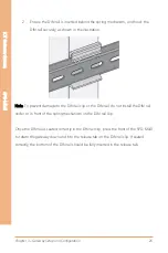
Page 37: ... To prevent damage to the DIN rail clip or the DIN rail do not install the DIN rail under or in front of the spring mechanism on the DIN rail clip Once the DIN rail is seated correctly in the DIN rail clip press the front of the SPG M041 to rotate the gateway down and into the release tab on the DIN rail clip If seated correctly the bottom of the DIN rail should be fully inserted in the release ta...

Page 38: ...Rail Mount 1 Turn off disconnect power from the IIoT gateway and disconnect all cables and connectors from the front panel of the SPG M041 2 Push down on the top of the DIN rail clip lift with finger As the clip releases lift the bottom of the SPG M041 as shown in the following illustration ...

Reviews: