background image

A S U S   A 8 N 5 X

A S U S   A 8 N 5 X

A S U S   A 8 N 5 X

A S U S   A 8 N 5 X

A S U S   A 8 N 5 X

3 - 9

3 - 9

3 - 9

3 - 9

3 - 9

3.

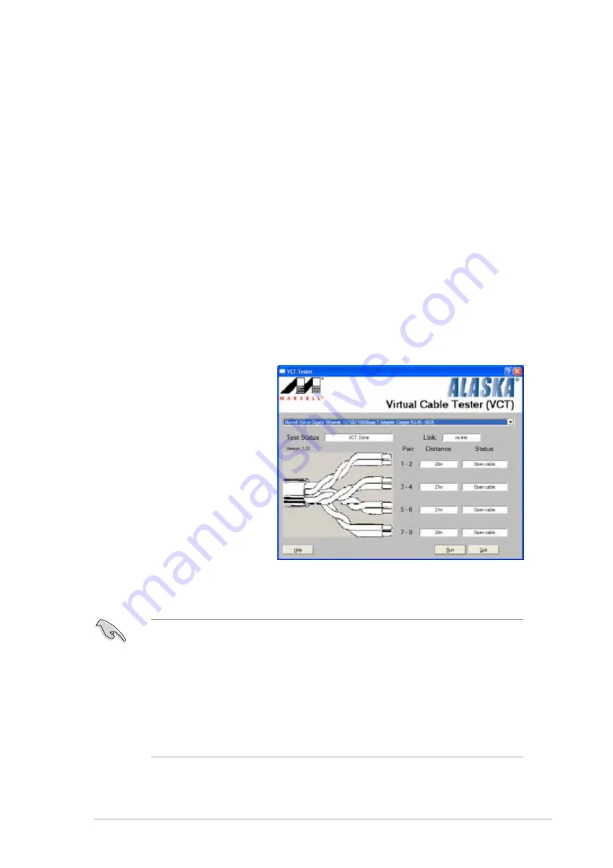
Click the R u n

R u n

R u n

R u n

R u n button to perform a cable test.

3.3.2

3.3.2

3.3.2

3.3.2

3.3.2

AI NET 2

AI NET 2

AI NET 2

AI NET 2

AI NET 2

The Marvell

®

 Virtual Cable Tester™ (VCT) is a cable diagnostic utility that

reports LAN cable faults and shorts using the Time Domain Reflectometry
(TDR) technology. The VCT detects and reports open and shorted cables,
impedance mismatches, pair swaps, pair polarity problems, and pair skew
problems of up to 100 meters at one meter accuracy.

The VCT feature reduces networking and support costs through a highly
manageable and controlled network system. This utility can be incorporated
in the network systems sofware for ideal field support as well as
development diagnostics.

Using the Virtual Cable Tester™

Using the Virtual Cable Tester™

Using the Virtual Cable Tester™

Using the Virtual Cable Tester™

Using the Virtual Cable Tester™

To use the the Marvell

®

 Virtual Cable Tester™  utility:

1.

Launch the VCT utility from the Windows

®

 desktop by clicking

S t a r t >   A l l   P r o g r a m s   >   M a r v e l l   >   V i r t u a l   C a b l e   T e s t e r

S t a r t >   A l l   P r o g r a m s   >   M a r v e l l   >   V i r t u a l   C a b l e   T e s t e r

S t a r t >   A l l   P r o g r a m s   >   M a r v e l l   >   V i r t u a l   C a b l e   T e s t e r

S t a r t >   A l l   P r o g r a m s   >   M a r v e l l   >   V i r t u a l   C a b l e   T e s t e r

S t a r t >   A l l   P r o g r a m s   >   M a r v e l l   >   V i r t u a l   C a b l e   T e s t e r.

2.

Click V i r t u a l   C a b l e

V i r t u a l   C a b l e

V i r t u a l   C a b l e

V i r t u a l   C a b l e

V i r t u a l   C a b l e

T e s t e r  

T e s t e r  

T e s t e r  

T e s t e r  

T e s t e r  from the menu
to display the screen
below.

The VCT only runs on systems with Windows

®

 XP or Windows

®

 2000

operating systems.

The R u n

R u n

R u n

R u n

R u n button on the Virtual Cable Tester™ main window is

disabled if no problem is detected on the LAN cable(s) connected to
the LAN port(s).

If you want the system to check the LAN cable before entering the
OS, enable the P O S T   C h e c k   L A N   c a b l e

P O S T   C h e c k   L A N   c a b l e

P O S T   C h e c k   L A N   c a b l e

P O S T   C h e c k   L A N   c a b l e

P O S T   C h e c k   L A N   c a b l e item in the BIOS. See

section “2.4.5 LAN Cable Status” for details.

Summary of Contents for A8N5X

Page 1: ...Motherboard A8N5X ...

Page 2: ...ORS OFFICERS EMPLOYEES OR AGENTS BE LIABLE FOR ANY INDIRECT SPECIAL INCIDENTAL OR CONSEQUENTIAL DAMAGES INCLUDING DAMAGES FOR LOSS OF PROFITS LOSS OF BUSINESS LOSS OF USE OR DATA INTERRUPTION OF BUSINESS AND THE LIKE EVEN IF ASUS HAS BEEN ADVISED OF THE POSSIBILITY OF SUCH DAMAGES ARISING FROM ANY DEFECT OR ERROR IN THIS MANUAL OR PRODUCT SPECIFICATIONS AND INFORMATION CONTAINED IN THIS MANUAL ARE...

Page 3: ...3 1 3 1 Product highlights 1 3 1 3 2 ASUS Proactive features 1 5 1 3 3 Innovative ASUS features 1 6 1 4 Before you proceed 1 7 1 5 Motherboard overview 1 8 1 5 1 Placement direction 1 8 1 5 2 Screw holes 1 8 1 5 3 Motherboard layout 1 9 1 6 Central Processing Unit CPU 1 10 1 6 1 Overview 1 10 1 6 2 Installling the CPU 1 10 1 6 3 Installing the heatsink and fan 1 12 1 7 System memory 1 15 1 7 1 Ove...

Page 4: ... 1 4 ASUS CrashFree BIOS 2 utility 2 6 2 1 5 ASUS EZ Flash utility 2 8 2 1 6 ASUS Update utility 2 9 2 2 BIOS setup program 2 12 2 2 1 BIOS menu screen 2 13 2 2 2 Menu bar 2 13 2 2 3 Legend bar 2 14 2 2 4 Menu items 2 14 2 2 5 Sub menu items 2 14 2 2 6 Configuration fields 2 14 2 2 8 General help 2 15 2 2 7 Pop up window 2 15 2 3 Main menu 2 16 2 3 1 System Time 2 16 2 3 2 System Date 2 16 2 3 3 L...

Page 5: ...DROM Drives 2 37 2 6 5 Boot Settings Configuration 2 38 2 6 6 Security 2 39 2 7 Exit menu 2 41 Chapter 3 Software support Chapter 3 Software support Chapter 3 Software support Chapter 3 Software support Chapter 3 Software support 3 1 Installing an operating system 3 2 3 2 Support CD information 3 2 3 2 1 Running the support CD 3 2 3 2 2 Drivers menu 3 3 3 2 3 Utilities menu 3 4 3 2 4 Manuals menu ...

Page 6: ...3 21 3 4 1 Installing hard disks 3 22 3 4 2 NVIDIA RAID configurations 3 23 3 5 Creating a RAID driver disk 3 30 3 6 Cool n Quiet Technology 3 31 3 6 1 Enabling Cool n Quiet Technology 3 31 3 6 2 Launching the Cool n Quiet software 3 32 Contents ...

Page 7: ...e user is encouraged to try to correct the interference by one or more of the following measures Reorient or relocate the receiving antenna Increase the separation between the equipment and receiver Connect the equipment to an outlet on a circuit different from that to which the receiver is connected Consult the dealer or an experienced radio TV technician for help Canadian Department of Communica...

Page 8: ... correct voltage in your area If you are not sure about the voltage of the electrical outlet you are using contact your local power company If the power supply is broken do not try to fix it by yourself Contact a qualified service technician or your retailer Operation safety Operation safety Operation safety Operation safety Operation safety Before installing the motherboard and adding devices on ...

Page 9: ...m settings through the BIOS Setup menus Detailed descriptions of the BIOS parameters are also provided Chapter 3 Software support Chapter 3 Software support Chapter 3 Software support Chapter 3 Software support Chapter 3 Software support This chapter describes the contents of the support CD that comes with the motherboard package Where to find more information Where to find more information Where ...

Page 10: ... NOTE Tips and additional information to help you complete a task IMPORTANT IMPORTANT IMPORTANT IMPORTANT IMPORTANT Instructions that you MUST follow to complete a task Bold text Bold text Bold text Bold text Bold text Indicates a menu or an item to select Italics Used to emphasize a word or a phrase Key Keys enclosed in the less than and greater than sign means that you must press the enclosed ke...

Page 11: ...ure 4 x 184 pin DIMM sockets support ECC non ECC unbufferred 400 333 266 MHz DDR memory modules Supports up to 4 GB system memory 1 x PCI Express x16 slots 2 x PCI Express x1 slots 1 x PCI Express x4 slot Note Supports a total bandwidth of 1GB s 3 x PCI slots NVIDIA nForce 4 chipset supports 2 x Ultra DMA 133 100 66 33 4 x Serial ATA with RAID 0 RAID 1 RAID 1 0 and JBOD that spans across the Seria...

Page 12: ...ATX power connector 1 x 4 pin ATX 12 V power connector 3 x USB 2 0 connectors for 6 additional USB 2 0 ports 1 x Internal audio connectors CD AUX 1 x GAME MIDI connector 1 x Chassis intrusion connector 1 x Front panel audio connector System panel connector NVIDIA nForce 4 built in Gigabit MAC with external Marvell PHY supports NV Firewall AI NET2 Realtek ALC850 8 channel CODEC 1 x Coaxial S PDIF o...

Page 13: ...pport CD Support CD Support CD Support CD Support CD contents contents contents contents contents ATX form factor 12 in x 9 6 in 30 5 cm x 24 4 cm Device drivers ASUS PC Probe II ASUS Live Update utility ASUS Cool n Quiet utility Anti virus utility OEM version NVIDIA nTune utility Specifications are subject to change without notice ...

Page 14: ...x i v x i v x i v x i v x i v ...

Page 15: ...ASUS A8N5X ASUS A8N5X ASUS A8N5X ASUS A8N5X ASUS A8N5X 1 1 1 1 1 1 1 1 1 1 1 Product introduction This chapter describes the motherboard features and the new technologies it supports ...

Page 16: ... hardware devices on it check the items in your package with the list below If any of the above items is damaged or missing contact your retailer 1 2 Package contents Check your motherboard package for the following items Motherboard Motherboard Motherboard Motherboard Motherboard ASUS A8N5X motherboard I O modules I O modules I O modules I O modules I O modules USB 2 0 2 port module Cables Cables...

Page 17: ...opment See page 1 10 Built in NVFirewall Built in NVFirewall Built in NVFirewall Built in NVFirewall Built in NVFirewall The NVIDIA Firewall NVFirewall is an easy to use high performance desktop firewall application that protects your system from intruders Integrated into the NVIDIA nForce 4 chipset with the NVIDIA Gigabit Ethernet it provides advanced anti computer hacking technologies remote man...

Page 18: ...ID 1 RAID 1 0 and JBOD configuration for four SATA and two PATA connectors See page 3 21 for details PCI Express interface PCI Express interface PCI Express interface PCI Express interface PCI Express interface The motherboard fully supports PCI Express the latest I O interconnect technology that speeds up the PCI bus PCI Express features point to point serial interconnections between devices and ...

Page 19: ...stic tool that detects and reports Ethernet cable faults and shorts With this utility you can easily monitor the condition of the Ethernet cable s connected to the LAN RJ 45 port s During the bootup process AI NET 2 immediately diagnoses the LAN cable s and reports shorts and faults up to 100 meters at 1 meter accuracy See pages 2 30 and 3 9 for details AI Audio technology AI Audio technology AI A...

Page 20: ...echnology smartly adjusts the fan speeds according to the system loading to ensure quiet cool and efficient operation See page 2 35 for details ASUS Multi language BIOS ASUS Multi language BIOS ASUS Multi language BIOS ASUS Multi language BIOS ASUS Multi language BIOS The multi language BIOS allows you to select the language of your choice from the available options The localized BIOS menus allow ...

Page 21: ... any component ensure Before you install or remove any component ensure that the ATX power supply is switched off or the that the ATX power supply is switched off or the that the ATX power supply is switched off or the that the ATX power supply is switched off or the that the ATX power supply is switched off or the power cord is detached from the power supply power cord is detached from the power ...

Page 22: ...5 1 1 5 1 1 5 1 1 5 1 1 5 1 Placement direction Placement direction Placement direction Placement direction Placement direction When installing the motherboard make sure that you place it into the chassis in the correct orientation The edge with external ports goes to the rear part of the chassis as indicated in the image below 1 5 2 1 5 2 1 5 2 1 5 2 1 5 2 Screw holes Screw holes Screw holes Scre...

Page 23: ...m Cell CMOS Power AUX FP_AUDIO GAME CHASSIS PRI_IDE SEC_IDE EATXPWR COM1 24 5cm 9 6in 30 5cm 12 0in CPU_FAN Socket 939 DDR DIMM_B1 64 bit 184 pin module DDR DIMM_A1 64 bit 184 pin module DDR DIMM_A2 64 bit 184 pin module DDR DIMM_B2 64 bit 184 pin module CHA2_FAN USB12 PWR_FAN FLOPPY Super I O 4Mb BIOS PS 2KBMS T Mouse B Keyboard PARALLEL PORT SPDIF_O SPDIF_O2 LAN1_USB34 CD ACL850 PCIEX16_1 PCIEX1...

Page 24: ...ocate the CPU socket on the motherboard 1 6 Central Processing Unit CPU 1 6 1 1 6 1 1 6 1 1 6 1 1 6 1 Overview Overview Overview Overview Overview The motherboard comes with a surface mount 939 pin Zero Insertion Force ZIF socket designed for the AMD Athlon 64FX AMD Athlon 64 or AMD Sempron processor The 128 bit wide data paths of these processors can run applications faster than processors with o...

Page 25: ... Installing the heatsink and fan Installing the heatsink and fan Installing the heatsink and fan Installing the heatsink and fan Installing the heatsink and fan The AMD Athlon 64FX or AMD Athlon 64 processor require a specially designed heatsink and fan assembly to ensure optimum thermal condition and performance Make sure that you use only qualified heatsink and fan assembly The retention module ...

Page 26: ...on bracket DO NOT forget to connect the CPU fan connector Hardware monitoring error can occur if you fail to plug this connector 1 Place the heatsink on top of the installed CPU 2 Attach one end of the retention bracket to the retention module base 3 Align the other end of the retention bracket near the retention bracket lock to the retention module base A clicking sound denotes that the retention...

Page 27: ...nel must be the same for better performance DIMM_A1 DIMM_A2 DIMM_B1 DIMM_B2 When using one DDR DIMM module install into DIMM_B1 slot only When using two DDR DIMM modules install into DIMM_A1 and DIMM_B1 slots only Always install DIMMs with the same CAS latency For optimum compatibility it is recommended that you obtain memory modules from the same vendor Refer to the DDR400 Qualified Vendors List ...

Page 28: ...o m p o n e n t C o m p o n e n t C o m p o n e n t C o m p o n e n t C o m p o n e n t A A A A A B B B B B C C C C C 256MB KINGSTON KVR400X64C3A 256 Hynix SS HY5DU56822BT D43 512MB KINGSTON KVR400X64C3A 512 Hynix DS HY5DU56822BT D43 256MB KINGSTON KVR400X72C3A 256 Mosel SS V58C2256804SAT5 ECC 512MB KINGSTON KVR400X72C3A 512 Mosel DS V58C2256804SAT5 ECC 256MB KINGSTON KVR400X64C3A 256 Infineon SS ...

Page 29: ...DIMM is properly seated 1 Unlock a DIMM socket by pressing the retaining clips outward 2 Align a DIMM on the socket such that the notch on the DIMM matches the break on the socket Locked Retaining Clip Locked Retaining Clip Locked Retaining Clip Locked Retaining Clip Locked Retaining Clip Make sure to unplug the power supply before adding or removing DIMMs or other system components Failure to do ...

Page 30: ...ot that you intend to use Keep the screw for later use 4 Align the card connector with the slot and press firmly until the card is completely seated on the slot 5 Secure the card to the chassis with the screw you removed earlier 6 Replace the system cover 1 8 2 1 8 2 1 8 2 1 8 2 1 8 2 Configuring an expansion card Configuring an expansion card Configuring an expansion card Configuring an expansion...

Page 31: ...S 2 Compatible Mouse Port 13 8 Numeric Data Processor 14 9 Primary IDE Channel 15 10 Secondary IDE Channel These IRQs are usually available for ISA or PCI devices IRQ assignments for this motherboard IRQ assignments for this motherboard IRQ assignments for this motherboard IRQ assignments for this motherboard IRQ assignments for this motherboard A A A A A B B B B B C C C C C D D D D D E E E E E F ...

Page 32: ...s PCI Express x1 network cards SCSI cards and other cards that comply with the PCI Express specifications The figure shows a network card installed on the PCI Express x1 slot In Normal mode only the PCI Express blue slot can be used for PCI Express x16 graphics cards The PCI Express black slot functions as a PCI Express x1 slot 1 8 7 1 8 7 1 8 7 1 8 7 1 8 7 Universal PCIe slot PCI Express x4 slot ...

Page 33: ...the onboard battery 3 Move the jumper cap from pins 1 2 default to pins 2 3 Keep the cap on pins 2 3 for about 5 10 seconds then move the cap back to pins 1 2 4 Re install the battery 5 Plug the power cord and turn ON the computer 6 Hold down the Del key during the boot process and enter BIOS setup to re enter data Except when clearing the RTC RAM never remove the cap on CLRTC jumper default posit...

Page 34: ...de Speaker Out port black Side Speaker Out port black Side Speaker Out port black Side Speaker Out port black Side Speaker Out port black This port connects the side speakers in an 8 channel audio configuration 6 6 6 6 6 Line In port light blue Line In port light blue Line In port light blue Line In port light blue Line In port light blue This port connects the tape CD DVD player or other audio so...

Page 35: ...t device via a coaxial S PDIF cable 14 14 14 14 14 PS 2 keyboard port purple PS 2 keyboard port purple PS 2 keyboard port purple PS 2 keyboard port purple PS 2 keyboard port purple This port is for a PS 2 keyboard Audio 2 4 6 or 8 channel configuration Audio 2 4 6 or 8 channel configuration Audio 2 4 6 or 8 channel configuration Audio 2 4 6 or 8 channel configuration Audio 2 4 6 or 8 channel confi...

Page 36: ...1 10 2 1 10 2 1 10 2 Internal connectors Internal connectors Internal connectors Internal connectors Internal connectors 1 1 1 1 1 Floppy disk drive connector 34 1 pin FLOPPY Floppy disk drive connector 34 1 pin FLOPPY Floppy disk drive connector 34 1 pin FLOPPY Floppy disk drive connector 34 1 pin FLOPPY Floppy disk drive connector 34 1 pin FLOPPY This connector is for the provided floppy disk dr...

Page 37: ...the Parallel ATA drives Refer to Chapter 3 for details on how to set up RAID configurations These connectors are set to SATA SATA SATA SATA SATA by default In SATA mode you can connect Serial ATA boot or data hard disk drives to these connectors If you intent to create a Serial ATA RAID set using these connectors enable the RAID function of each port from the NVRAID NVRAID NVRAID NVRAID NVRAID Con...

Page 38: ...R_FAN 3 pin CHA1_FAN 3 pin PWR_FAN 3 pin CHA1_FAN 3 pin PWR_FAN 3 pin CHA1_FAN The fan connectors support cooling fans of 350mA 2000mA 24 W max or a total of 1A 3 48A 41 76 W max at 12V Connect the fan cables to the fan connectors on the motherboard making sure that the black wire of each cable matches the ground pin of the connector Do not forget to connect the fan cables to the fan connectors La...

Page 39: ...board 6 6 6 6 6 USB connectors 10 1 pin USB56 USB78 USB910 USB connectors 10 1 pin USB56 USB78 USB910 USB connectors 10 1 pin USB56 USB78 USB910 USB connectors 10 1 pin USB56 USB78 USB910 USB connectors 10 1 pin USB56 USB78 USB910 These connectors are for USB 2 0 ports Connect the USB GAME module cable to any of these connectors then install the module to a slot opening at the back of the system c...

Page 40: ...ply plugs are designed to fit these connectors in only one orientation Find the proper orientation and push down firmly until the connectors completely fit Use of a power supply unit PSU with a higher power output is recommended when configuring a system with more power consuming devices The system may become unstable or may not boot up if the power is inadequate Make sure that your PSU can provid...

Page 41: ...r 16 1 pin GAME GAME MIDI port connector 16 1 pin GAME GAME MIDI port connector 16 1 pin GAME This connector is for a GAME MIDI port Connect the USB GAME module cable to this connector then install the module to a slot opening at the back of the system chassis The GAME MIDI port connects a joystick or game pad for playing games and MIDI devices for playing or editing audio files The function of th...

Page 42: ... pin CHASSIS Chassis intrusion connector 4 1 pin CHASSIS Chassis intrusion connector 4 1 pin CHASSIS Chassis intrusion connector 4 1 pin CHASSIS This connector is for a chassis mounted intrusion detection sensor or switch Connect one end of the chassis intrusion sensor or switch cable to this connector The chassis intrusion sensor or switch sends a high level signal to this connector when a chassi...

Page 43: ...tor The IDE LED lights up or flashes when data is read from or written to the HDD System warning speaker Orange 4 pin SPEAKER System warning speaker Orange 4 pin SPEAKER System warning speaker Orange 4 pin SPEAKER System warning speaker Orange 4 pin SPEAKER System warning speaker Orange 4 pin SPEAKER This 4 pin connector is for the chassis mounted system warning speaker The speaker allows you to h...

Page 44: ...1 30 1 30 1 30 1 30 1 30 Chapter 1 Product introduction Chapter 1 Product introduction Chapter 1 Product introduction Chapter 1 Product introduction Chapter 1 Product introduction ...

Page 45: ... A8N5X ASUS A8N5X ASUS A8N5X ASUS A8N5X 2 1 2 1 2 1 2 1 2 1 2 BIOS setup This chapter tells how to change the system settings through the BIOS Setup menus Detailed descriptions of the BIOS parameters are also provided ...

Page 46: ...loppy disk Creating a bootable floppy disk 1 Do either one of the following to create a bootable floppy disk DOS environment a Insert a 1 44MB floppy disk into the drive b At the DOS prompt type format A S then press Enter Windows XP environment a Insert a 1 44 MB floppy disk to the floppy disk drive b Click Start Start Start Start Start from the Windows desktop then select M y M y M y M y M y Com...

Page 47: ...web site Rename the file to A8N5X BIN A8N5X BIN A8N5X BIN A8N5X BIN A8N5X BIN and save it to a floppy disk Save only the updated BIOS file in the floppy disk to avoid loading the wrong BIOS file 2 Copy the AwardBIOS Flash Utility awdflash exe from the Software folder of the support CD to the floppy disk with the latest BIOS file 3 Boot the system in DOS mode using the bootable floppy disk you crea...

Page 48: ...chnologies Ltd All Rights Reserved Warning Don t Turn Off Power Or Reset System For NF KC804 A8N5X 00 DATE 11 18 2004 Flash Type SST 49LF004A B 3 3V File Name to Program 1001 bin Program Flashing Memory OFE00 OK Write OK No Update Write Fail 123 123 123 123 1234567890123456789012345678901 1234567890123456789012345678901 1234567890123456789012345678901 123 123 123 123 123 123 123 123 Message Do You...

Page 49: ...C804 A8N5X 00 DATE 11 18 2004 Flash Type SST 49LF004A B 3 3V File Name to Program 1001 bin Save current BIOS as AwardBIOS Flash Utility for ASUS V1 01 C Phoenix Technologies Ltd All Rights Reserved Message Please Wait For NF KC804 A8N5X 00 DATE 11 18 2004 Flash Type SST 49LF004A B 3 3V File Name to Program 1001 bin Checksum DAD6H Save current BIOS as old bin AwardBIOS Flash Utility for ASUS V1 01 ...

Page 50: ... BIOS from the support CD Recovering the BIOS from the support CD Recovering the BIOS from the support CD Recovering the BIOS from the support CD Recovering the BIOS from the support CD To recover the BIOS from the support CD 1 Turn on the system 2 Insert the motherboard support CD to the optical drive 3 The utility displays the following message and automatically checks the CD for the BIOS file 4...

Page 51: ... file to the floppy disk drive 3 The utility displays the following message and automatically checks the floppy disk for the original or updated BIOS file 4 Restart the system after the utility completes the updating process DO NOT shut down or reset the system while updating the BIOS Doing so can cause system boot failure When no CD is found the utility automatically checks the floppy drive for t...

Page 52: ...it the ASUS website www asus com to download the latest BIOS file for the motherboard 2 Save the BIOS file to a floppy disk then restart the system 3 Press Alt F2 during POST to display the following Insert Disk then press Enter or ESC to continue POST 4 Insert the floppy disk that contains the BIOS file to the floppy disk drive then press Enter The following screen appears Do not shutdown or rese...

Page 53: ...screen menu 3 The ASUS Update utility is copied to your system 2 1 6 2 1 6 2 1 6 2 1 6 2 1 6 ASUS Update utility ASUS Update utility ASUS Update utility ASUS Update utility ASUS Update utility The ASUS Update is a utility that allows you to manage save and update the motherboard BIOS in Windows environment The ASUS Update utility allows you to Save the current BIOS file Download the latest BIOS fi...

Page 54: ...gh the Internet Updating the BIOS through the Internet To update the BIOS through the Internet 1 Launch the ASUS Update utility from the Windows desktop by clicking Start Start Start Start Start Programs Programs Programs Programs Programs ASUS ASUS ASUS ASUS ASUS ASUSUpdate ASUSUpdate ASUSUpdate ASUSUpdate ASUSUpdate ASUSUpdate ASUSUpdate ASUSUpdate ASUSUpdate ASUSUpdate The ASUS Update main wind...

Page 55: ...Update ASUSUpdate ASUSUpdate ASUSUpdate ASUSUpdate ASUSUpdate The ASUS Update main window appears 2 Select Update BIOS from a Update BIOS from a Update BIOS from a Update BIOS from a Update BIOS from a file file file file file option from the drop down menu then click Next Next Next Next Next 4 From the FTP site select the BIOS version that you wish to download Click Next 5 Follow the screen instr...

Page 56: ...m Press Del during the Power On Self Test POST to enter the Setup utility otherwise POST continues with its test routines If you wish to enter Setup after POST restart the system by pressing Ctrl Alt Delete or by pressing the reset button on the system chassis You can also restart by turning the system off and then back on Do this last option only if the first two failed The Setup program is desig...

Page 57: ...ed For changing the advanced system settings Power Power Power Power Power For changing the advanced power management APM configuration Boot Boot Boot Boot Boot For changing the system boot configuration Exit Exit Exit Exit Exit For selecting the exit options and loading default settings To select an item on the menu bar press the right or left arrow key on the keyboard until the desired item is h...

Page 58: ...er to display a list of options Refer to 2 2 7 Pop up window 2 2 3 2 2 3 2 2 3 2 2 3 2 2 3 Legend bar Legend bar Legend bar Legend bar Legend bar At the bottom of the Setup screen is a legend bar The keys in the legend bar allow you to navigate through the various setup menus The following table lists the keys found in the legend bar with their corresponding functions Navigation Key Navigation Key...

Page 59: ...ize of diskette drive A System Time 15 30 36 System Date Wed Nov 5 2004 Language English Legacy Diskette A 1 44M 3 5 in Primary IDE Master ST321122A Primary IDE Slave ASUS CDS520 A Secondary IDE Master None Secondary IDE Slave None First SATA Master None Second SATA Slave None Third SATA Master None Fourth SATA Slave None HDD SMART Monitoring Disabled Installed Memory 256MB 2 2 8 2 2 8 2 2 8 2 2 8...

Page 60: ...stem information Refer to section 2 2 1 BIOS menu screen for information on the menu screen items and how to navigate through them 2 3 1 2 3 1 2 3 1 2 3 1 2 3 1 System Time xx xx xxxx System Time xx xx xxxx System Time xx xx xxxx System Time xx xx xxxx System Time xx xx xxxx Allows you to set the system time 2 3 2 2 3 2 2 3 2 2 3 2 2 3 2 System Date Day xx xx xxxx System Date Day xx xx xxxx System...

Page 61: ...uration options Disabled Auto IDE Primary Master Slave Auto IDE Secondary Master IDE Primary Master Slave Auto IDE Secondary Master IDE Primary Master Slave Auto IDE Secondary Master IDE Primary Master Slave Auto IDE Secondary Master IDE Primary Master Slave Auto IDE Secondary Master Slave Auto Slave Auto Slave Auto Slave Auto Slave Auto Select Auto to automatically detect an IDE hard disk drive I...

Page 62: ...hard disk read write heads This item is not configurable Sector Sector Sector Sector Sector Shows the number of sectors per track This item is not configurable Transfer Mode Transfer Mode Transfer Mode Transfer Mode Transfer Mode Shows the Transfer mode This item is not configurable After entering the IDE hard disk drive information into BIOS use a disk utility such as FDISK to partition and forma...

Page 63: ...elects the type of fixed disk connected to the system Configuration options None Auto Access Mode Access Mode Access Mode Access Mode Access Mode Sets the sector addressing mode Configuration options Large Auto F1 Help Select Item Change Value F5 Setup Defaults ESC Exit Select Menu Enter Select Sub menu F10 Save and Exit Phoenix Award BIOS CMOS Setup Utility Main Select Menu Item Specific Help Pre...

Page 64: ...ack This item is not configurable After entering the IDE hard disk drive information into BIOS use a disk utility such as FDISK to partition and format new IDE hard disk drives This is necessary so that you can write or read data from the hard disk Make sure to set the partition of the Primary IDE hard disk drives to active 2 3 7 2 3 7 2 3 7 2 3 7 2 3 7 HDD SMART Monitoring HDD SMART Monitoring HD...

Page 65: ...2 4 Advanced menu The Advanced menu items allow you to change the settings for the CPU and other system devices Take caution when changing the settings of the Advanced menu items Incorrect field values can cause the system to malfunction F1 Help Select Item Change Value F5 Setup Defaults ESC Exit Select Menu Enter Select Sub menu F10 Save and Exit DRAM Configuration DRAM Configuration DRAM Configu...

Page 66: ...inimum RAS active time Configuration options Auto 5 6 7 8 9 10 11 12 13 14 15 Row precharge Time Trp Auto Sets the Row precharge time Precharge to Active or Auto Refresh of the same bank Configuration options Auto 2 3 4 5 6 Master ECC Enable Disabled Enables or disables the master ECC function Configuration options Disabled Enabled Hyper Transport Frequency Auto Hyper Transport Frequency Auto Hype...

Page 67: ...ase address fields Configuration options Auto Manual When the item Resources Controlled By is set to Auto the item IRQ Resources is grayed out and not user configurable Refer to the section IRQ Resources for information on how to enable this item IRQ Resources IRQ Resources IRQ Resources IRQ Resources IRQ Resources This sub menu is activated only when the Resources Controlled By Resources Controll...

Page 68: ...d F1 Help Select Item Change Value F5 Setup Defaults ESC Exit Select Menu Enter Select Sub menu F10 Save and Exit Select Menu Item Specific Help Onboard Device Configuration IDE Function Setup NVRAID Configuration USB Configuration Onboard NV LAN Enabled Onboard LAN Boot ROM Disabled AC97 Audio Enabled Serial Port1 Address 3F8 IRQ4 Parallel Port Address 378 IRQ7 Parallel Port Mode ECP EPP ECP MOde...

Page 69: ... transfer Enabled SATA DMA transfer Enabled SATA DMA transfer Enabled Allows you to enable or disable the SATA DMA transfer access Configuration options Disabled Enabled IDE Prefetch Mode Enabled IDE Prefetch Mode Enabled IDE Prefetch Mode Enabled IDE Prefetch Mode Enabled IDE Prefetch Mode Enabled Allows you to enable or disable the IDE prefetch mode Configuration options Disabled Enabled NVRAID ...

Page 70: ...bled Onboard NV LAN Enabled Onboard NV LAN Enabled Onboard NV LAN Enabled Onboard NV LAN Enabled Onboard NV LAN Enabled Enables or disables the onboard NVIDIA Gigabit LAN controller Configuration options Enabled Disabled OnBoard LAN Boot ROM Disabled OnBoard LAN Boot ROM Disabled OnBoard LAN Boot ROM Disabled OnBoard LAN Boot ROM Disabled OnBoard LAN Boot ROM Disabled Allows you to enable or disab...

Page 71: ...rt Mode ECP EPP Parallel Port Mode ECP EPP Allows you to select the Parallel Port mode Configuration options Normal Bi directional EPP ECP ECP Mode Use DMA 3 ECP Mode Use DMA 3 ECP Mode Use DMA 3 ECP Mode Use DMA 3 ECP Mode Use DMA 3 Allows selection of ECP Mode Configuration options 1 3 Game Port Address 201 Game Port Address 201 Game Port Address 201 Game Port Address 201 Game Port Address 201 A...

Page 72: ...rd Standard Standard Standard Standard Loads the standard settings for the system AI Overclock AI Overclock AI Overclock AI Overclock AI Overclock Loads overclocking profiles with optimal parameters for stability when overclocking AI N O S AI N O S AI N O S AI N O S AI N O S The ASUS AI Non delay Overclocking System feature intelligently determines the system load and automatically boost the perfo...

Page 73: ... x15 x15 5 x16 x16 5 x17 x17 5 x18 x18 5 x19 x19 5 x20 CPU Voltage Auto CPU Voltage Auto CPU Voltage Auto CPU Voltage Auto CPU Voltage Auto Sets the operating CPU voltage Configuration options Auto 1 650V 1 6375V 1 625V 1 6125V 1 600V 1 5875V 1 575V 1 5625V 1 550V 1 5375V 1 525V 1 5125V 1 500V 1 4875V 1 475V 1 4625V 1 450V 1 4375V 1 425V 1 4125V 1 400V 1 3875V 1 375V 1 3625V 1 350V 1 3375V 1 325V ...

Page 74: ... cable Disabled POST Check LAN cable Disabled Enables or disables checking of the LAN cable during the Power On Self Test POST Configuration options Disabled Enabled 2 4 5 2 4 5 2 4 5 2 4 5 2 4 5 LAN Cable Status LAN Cable Status LAN Cable Status LAN Cable Status LAN Cable Status The items in this menu displays the status of the Local Area Network LAN cable Select Menu Item Specific Help JumperFre...

Page 75: ... wish to use for the Instant Music CD playback Configuration options Primary Master Primary Slave Secondary Master Secondary Slave 2 4 7 2 4 7 2 4 7 2 4 7 2 4 7 Instant Music Instant Music Instant Music Instant Music Instant Music Select Menu Item Specific Help If enabled power up by PS 2 keyboard function will be disabled JumperFree Configuration Instant Music Disabled x Instant Music CD ROM Driv...

Page 76: ...nge Value F5 Setup Defaults ESC Exit Select Menu Enter Select Sub menu F10 Save and Exit 2 5 1 2 5 1 2 5 1 2 5 1 2 5 1 ACPI Suspend Type S1 S3 ACPI Suspend Type S1 S3 ACPI Suspend Type S1 S3 ACPI Suspend Type S1 S3 ACPI Suspend Type S1 S3 Allows you to select the Advanced Configuration and Power Interface ACPI state to be used for system suspend Configuration options S1 POS S3 STR S1 S3 2 5 2 2 5 ...

Page 77: ...ecs Instant Off PWR Button 4 secs Instant Off PWR Button 4 secs Instant Off PWR Button 4 secs Instant Off Allows you to set the event after the power button is pressed for more than 4 seconds Configuration options Suspend Instant Off Power On By PCI Devices Disabled Power On By PCI Devices Disabled Power On By PCI Devices Disabled Power On By PCI Devices Disabled Power On By PCI Devices Disabled W...

Page 78: ...Disabled To set the time of alarm 1 Highlight this item and press Enter to display a pop up menu for the hour field 2 Key in a value Min 0 Max 23 then press Enter 3 Press TAB to move to the minutes field then press Enter 4 Key in a minute value Min 0 Max 59 then press Enter 5 Press TAB to move to the seconds field then press Enter 6 Key in a value Min 0 Max 59 then press Enter Power Up By PS 2 Mou...

Page 79: ...s you to enable or disable the Q Fan controller Configuration options Disabled Enabled VCORE Voltage 12V Voltage 3 3V Voltage 5VCC VCORE Voltage 12V Voltage 3 3V Voltage 5VCC VCORE Voltage 12V Voltage 3 3V Voltage 5VCC VCORE Voltage 12V Voltage 3 3V Voltage 5VCC VCORE Voltage 12V Voltage 3 3V Voltage 5VCC Voltage Voltage Voltage Voltage Voltage The onboard hardware monitor automatically detects th...

Page 80: ...st xxth Boot Device Removable 1st xxth Boot Device Removable 1st xxth Boot Device Removable 1st xxth Boot Device Removable 1st xxth Boot Device Removable These items specify the boot device priority sequence from the available devices The number of device items that appears on the screen depends on the number of devices installed in the system Configuration options Removable Hard Disk CDROM Legacy...

Page 81: ...Hard Disk Drives Hard Disk Drives 1 1st Master XXXXXXXXX 1 1st Master XXXXXXXXX 1 1st Master XXXXXXXXX 1 1st Master XXXXXXXXX 1 1st Master XXXXXXXXX Allows you to assign hard disk drives attached to the system Select Menu Item Specific Help Hard Disk Drives 1 1st Master XXXXXXXXX 2 Bootable Add in Cards Phoenix Award BIOS CMOS Setup Utility Boot 2 6 4 2 6 4 2 6 4 2 6 4 2 6 4 CDROM Drives CDROM Dri...

Page 82: ...led Allows you to enable or disable the system quick boot feature When Enabled the system skips certain tests while booting Configuration options Disabled Enabled Boot Up Floppy Seek Enabled Boot Up Floppy Seek Enabled Boot Up Floppy Seek Enabled Boot Up Floppy Seek Enabled Boot Up Floppy Seek Enabled Enable this item to allow the BIOS to check a boot floppy disk during POST Configuration options ...

Page 83: ... LOGO Enabled Full Screen LOGO Enabled Full Screen LOGO Enabled Allows you to enable or disable the full screen logo display feature Configuration options Disabled Enabled Make sure that the above item is set to Enabled if you want to use the ASUS MyLogo2 feature See section 3 3 1 ASUS MyLogo2 for details Halt On All Errors Halt On All Errors Halt On All Errors Halt On All Errors Halt On All Error...

Page 84: ...o enter the BIOS Setup program preventing unauthorized access The User password is required to boot the system preventing unauthorized use Forgot your password Forgot your password Forgot your password Forgot your password Forgot your password If you forget your password you can clear it by erasing the CMOS Real Time Clock RTC RAM The RAM data containing the password information is powered by the ...

Page 85: ... Exit menu to ensure the values you selected are saved to the CMOS RAM An onboard backup battery sustains the CMOS RAM so it stays on even when the PC is turned off When you select this option a confirmation window appears Select Y e s Y e s Y e s Y e s Y e s to save changes and exit Pressing Esc does not immediately exit this menu Select one of the options from this menu or F10 from the legend ba...

Page 86: ...nfirmation window appears Select Y e s Y e s Y e s Y e s Y e s to load default values Select Exit Save Changes Exit Save Changes Exit Save Changes Exit Save Changes Exit Save Changes or make other changes before saving the values to the non volatile RAM Discard Changes Discard Changes Discard Changes Discard Changes Discard Changes This option allows you to discard the selections you made and rest...

Page 87: ...ASUS A8N5X ASUS A8N5X ASUS A8N5X ASUS A8N5X ASUS A8N5X 3 1 3 1 3 1 3 1 3 1 3 Software support This chapter describes the contents of the support CD that comes with the motherboard package ...

Page 88: ...l motherboard features 3 2 1 3 2 1 3 2 1 3 2 1 3 2 1 Running the support CD Running the support CD Running the support CD Running the support CD Running the support CD Place the support CD to the optical drive The CD automatically displays the Drivers Drivers Drivers Drivers Drivers menu if Autorun is enabled in your computer Motherboard settings and hardware options vary Use the setup procedures ...

Page 89: ...TA RAID Driver Disk Creates the NVIDIA driver disk for Parallel ATA and RAID features Make NVIDIA SATA RAID Driver Disk Make NVIDIA SATA RAID Driver Disk Make NVIDIA SATA RAID Driver Disk Make NVIDIA SATA RAID Driver Disk Make NVIDIA SATA RAID Driver Disk Creates the NVIDIA driver disk for Serial ATA and RAID features Realtek ALC850 Driver Realtek ALC850 Driver Realtek ALC850 Driver Realtek ALC850...

Page 90: ...S Update ASUS Update ASUS Update ASUS Update Allows you to download the latest version of the BIOS from the ASUS website Before using the ASUS Update make sure that you have an Internet connection so you can connect to the ASUS website ASUS AI Booster ASUS AI Booster ASUS AI Booster ASUS AI Booster ASUS AI Booster The ASUS AI Booster application allows you to overclock the CPU speed in a Windows e...

Page 91: ...S AMD Cool n Quiet Software ASUS AMD Cool n Quiet Software ASUS AMD Cool n Quiet Software Installs the AMD Cool n Quiet software 3 2 4 3 2 4 3 2 4 3 2 4 3 2 4 Manuals menu Manuals menu Manuals menu Manuals menu Manuals menu The Manuals menu contains a list of supplementary user manuals Click an item to open the folder of the user manual Most user manual files are in Portable Document Format PDF In...

Page 92: ...ID User s Guide NVIDIA RAID User s Guide NVIDIA RAID User s Guide NVIDIA RAID User s Guide NVIDIA RAID User s Guide Allows you to open the NVIDIA RAID User s Guide Sil3114 User s Manual Sil3114 User s Manual Sil3114 User s Manual Sil3114 User s Manual Sil3114 User s Manual Allows you to open the Silicon Image RAID User s Guide NVIDIA nTune Manual NVIDIA nTune Manual NVIDIA nTune Manual NVIDIA nTun...

Page 93: ...lace system boot Launch MyLogo to replace system boot Launch MyLogo to replace system boot Launch MyLogo to replace system boot Launch MyLogo to replace system boot logo before flashing BIOS logo before flashing BIOS logo before flashing BIOS logo before flashing BIOS logo before flashing BIOS then click Next Next Next Next Next 4 Select Update BIOS from a file Update BIOS from a file Update BIOS ...

Page 94: ...urns to the ASUS Update utility flash the original BIOS to load the new boot logo 10 After flashing the BIOS restart the computer to display the new boot logo during POST 8 Adjust the boot image to your desired size by selecting a value on the Ratio Ratio Ratio Ratio Ratio box 7 When the logo images appear on the right window pane select an image to enlarge by clicking on it ...

Page 95: ...ter Using the Virtual Cable Tester Using the Virtual Cable Tester To use the the Marvell Virtual Cable Tester utility 1 Launch the VCT utility from the Windows desktop by clicking Start All Programs Marvell Virtual Cable Tester Start All Programs Marvell Virtual Cable Tester Start All Programs Marvell Virtual Cable Tester Start All Programs Marvell Virtual Cable Tester Start All Programs Marvell V...

Page 96: ...Realtek ALC850 Audio Driver and Application Driver and Application Driver and Application Driver and Application Driver and Application from the support CD that came with the motherboard package If the Realtek audio software is correctly installed you will find the SoundEffect icon on the taskbar From the taskbar double click on the SoundEffect SoundEffect SoundEffect SoundEffect SoundEffect icon ...

Page 97: ...ion buttons to change your S PDIF out settings 3 Click the Exit X X X X X button on the upper right hand corner of the window to exit To set the sound effect options 1 From the Realtek Audio Control Panel click the Sound Effect Sound Effect Sound Effect Sound Effect Sound Effect button 2 Click the shortcut buttons to change the acoustic environment adjust the equalizer or set the karaoke to your d...

Page 98: ...ion 1 From the Realtek Audio Control Panel click the Speaker Speaker Speaker Speaker Speaker Configuration Configuration Configuration Configuration Configuration button 2 Select from the combo list box your current speaker setup then click Auto Test Auto Test Auto Test Auto Test Auto Test to test your settings 3 Click the UAJ Automatic UAJ Automatic UAJ Automatic UAJ Automatic UAJ Automatic butto...

Page 99: ... sensing option that allows you to check if your audio devices are connected properly To start the connector sensing 1 From the Realtek Audio Control Panel click the Connector Sensing Connector Sensing Connector Sensing Connector Sensing Connector Sensing button 2 Click the Bracket Bracket Bracket Bracket Bracket button to display connected audio devices 3 Click the Option Option Option Option Opt...

Page 100: ...tton on the upper right hand corner of the window to exit audio control panel HRTF Demo HRTF Demo HRTF Demo HRTF Demo HRTF Demo This option shows a demo of the Head Related Transfer Functions HRTF To start the HRTF demo 1 From the Realtek Audio Control Panel click the HRTF Demo HRTF Demo HRTF Demo HRTF Demo HRTF Demo button 2 Click the option buttons to change the sound moving path or EAX settings...

Page 101: ...audio configuration See the 8 6 4 or 2 channel speaker configuration on page 1 21 General settings General settings General settings General settings General settings This option shows the audio settings and allows you to change the language setting or toggle the SoundEffect icon display on the Windows taskbar To display the general settings 1 From the Realtek Audio Control Panel click the General...

Page 102: ... CD it is automatically activated with a Medium Medium Medium Medium Medium security profile as its default setting The setup summary of NVFirewall is displayed in the summary menu To launch the NVFirewall summary menu 1 Click the NVIDIA NVIDIA NVIDIA NVIDIA NVIDIA Firewall icon Firewall icon Firewall icon Firewall icon Firewall icon from the Windows taskbar N V I D I A N V I D I A N V I D I A N V...

Page 103: ... invisible to intruders This also enables some anti hacking features Lockdown Lockdown Lockdown Lockdown Lockdown blocks all incoming and outgoing connections Anti hacking only Anti hacking only Anti hacking only Anti hacking only Anti hacking only this profile enables all anti hacking features but disables the firewall This security profile is useful if you want to use a third party firewall appl...

Page 104: ...n when using this option your computer becomes vulnerable to viruses hackers or intruders after you turn off the firewall To turn off the NVFirewall 1 From the NVIDIA Firewall summary menu click the Current Firewall Profile Current Firewall Profile Current Firewall Profile Current Firewall Profile Current Firewall Profile combo list box then select Off Off Off Off Off The following confirmation bo...

Page 105: ...tire system Use two new drives or use an existing drive and a new drive for this setup The new drive must be of the same size or larger than the existing drive RAID 0 1 RAID 0 1 RAID 0 1 RAID 0 1 RAID 0 1 is data striping and data mirroring combined without parity redundancy data having to be calculated and written With the RAID 0 1 configuration you get all the benefits of both RAID 0 and RAID 1 ...

Page 106: ...ng Parallel ATA hard disks To install IDE hard disks for a RAID configuration 1 Set the jumpers of each hard disk as Master Master or Slave Slave 2 Install the hard disks into the drive bays 3 Connect the HDD signal cables 4 Connect a 4 pin power cable to the power connector on each drive Installing Serial ATA SATA hard disks Installing Serial ATA SATA hard disks Installing Serial ATA SATA hard di...

Page 107: ...iguration To set the BIOS RAID items 1 Boot the system and press Del during the Power On Self Test POST to enter the BIOS Setup Utility 2 From the Advanced Onboard Devices Configuration Advanced Onboard Devices Configuration Advanced Onboard Devices Configuration Advanced Onboard Devices Configuration Advanced Onboard Devices Configuration NVRAID Configuration NVRAID Configuration NVRAID Configura...

Page 108: ...lect ENTER Popup At the bottom of the screen are the navigation keys These keys allow you to move through and select menu options NVIDIA RAID Utility Oct 5 2004 Define a New Array RAID Mode Striping Striping Block Optimal Free Disks Array Disks Loc Disk Model Name Loc Disk Model Name 1 0 M XXXXXXXXXXXXXXXXXX 1 1 M XXXXXXXXXXXXXXXXXX Add 2 0 M XXXXXXXXXXXXXXXXXX 2 1 M XXXXXXXXXXXXXXXXXX Del Creatin...

Page 109: ...cted Striping or Stripe Mirroring use the up or down arrow keys to select the stripe size for your RAID 0 array then press Enter The available values range from 8 KB to 128 KB The default selection is 128 KB The strip value should be chosen based on the planned drive usage 8 16 KB low disk usage 64 KB typical disk usage 128 KB performance disk usage 3 Press TAB to select the Free Disks area Use th...

Page 110: ...ss Enter The RAID Array details appear Ctrl X Exit Select B Set Boot N New Array ENTER Detail NVIDIA RAID Utility Oct 5 2004 Array List Boot Id Status Vendor Array Model Name No 4 Healthy NVIDIA MIRROR XXX XXG A new set of navigation keys is displayed on the bottom of the screen 6 Press Ctrl X to save settings and exit R Rebuild D Delete C Clear Disk ENTER Return Array 1 NVIDIA MIRROR XXX XXG Arra...

Page 111: ...ld then press F7 The following confirmation message appears Select F6 Back F7 Finish Array 1 NVIDIA MIRROR XXX XXG Select Disk Inside Array RAID Mode Mirroring Striping Width 1 Striping Block 64K Adapt Channel M S Index Disk Model Name Capacity 2 1 Master 0 XXXXXXXXXXXXXXXXX XXX XXGB 1 0 Master 1 XXXXXXXXXXXXXXXXX XXX XXGB Rebuild array ENTER OK ESC Cancel 4 Press Enter to start rebuilding array o...

Page 112: ...ebuild D Delete C Clear Disk ENTER Return Array 1 NVIDIA MIRROR XXX XXG Array Detail RAID Mode Mirroring Striping Width 1 Striping Block 64K Adapt Channel M S Index Disk Model Name Capacity 2 1 Master 0 XXXXXXXXXXXXXXXXX XXX XXGB 1 0 Master 1 XXXXXXXXXXXXXXXXX XXX XXGB A new set of navigation keys is displayed on the bottom of the screen 2 Press D to delete a RAID array The following confirmation ...

Page 113: ...ete C Clear Disk ENTER Return Array 1 NVIDIA MIRROR XXX XXG Array Detail RAID Mode Mirroring Striping Width 1 Striping Block 64K Adapt Channel M S Index Disk Model Name Capacity 2 1 Master 0 XXXXXXXXXXXXXXXXX XXX XXGB 1 0 Master 1 XXXXXXXXXXXXXXXXX XXX XXGB A new set of navigation keys is displayed on the bottom of the screen 2 Press C to clear disk The following confirmation message appears Take ...

Page 114: ...wing screen appears during POST 5 Place a blank high density floppy disk to the floppy disk drive then press the number of your choice The following message will appear 1 Make Sil3114 32bit SATA RAID Driver Disk 2 Make Sil3114 64bit SATA RAID Driver Disk 3 Make Nvidia 2000 RAID Driver Disk 4 Make Nvidia XP RAID Driver Disk 5 Make Nvidia 2003 RAID Driver Disk 6 Make Nvidia 64bit XP RAID Driver Disk...

Page 115: ... Power Power Power Power Power menu select the item ACPI 2 0 Support ACPI 2 0 Support ACPI 2 0 Support ACPI 2 0 Support ACPI 2 0 Support and set it to Y e s Y e s Y e s Y e s Y e s See section 2 5 Power Menu in the user guide 4 Save your changes and exit BIOS Setup 5 Reboot your computer and set your Power Option Properties depending on your operating system Windows Windows Windows Windows Windows...

Page 116: ...dows 2000 click the Start Start Start Start Start button Select Programs ASUS Cool Quiet Cool Quiet Programs ASUS Cool Quiet Cool Quiet Programs ASUS Cool Quiet Cool Quiet Programs ASUS Cool Quiet Cool Quiet Programs ASUS Cool Quiet Cool Quiet 2 If you are using Windows XP click the Start Start Start Start Start button Select A l l A l l A l l A l l A l l Programs ASUS Cool Quiet Cool Quiet Progra...

Reviews: