background image

5-2

Chapter 5: Software support
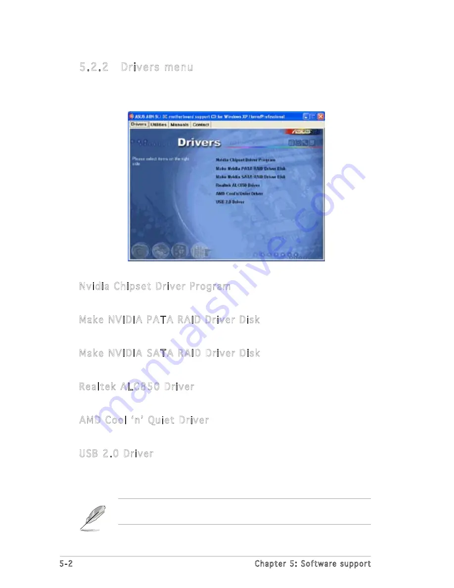
5.2.2  Drivers menu

The drivers menu shows the available device drivers if the system detects 

installed devices. Install the necessary drivers to activate the devices.

Nvidia Chipset Driver Program

Installs the NVIDIA

®

 Chipset drivers for the NVIDIA

®

 nForce™ 4 SLI chipset.  

Make NVIDIA PATA RAID Driver Disk

Creates the NVIDIA

®

  driver disk for Serial ATA and PATA RAID features.

Make NVIDIA SATA RAID Driver Disk

Creates the NVIDIA

®

  driver disk for Serial ATA and SATA RAID features.

Realtek ALC850 Driver

Installs the Realtek

®

 ALC850 audio controller and application.

AMD Cool ʻnʼ Quiet Driver

Installs the AMD Cool ʻnʼ Quiet Driver.

USB 2.0 Driver

Installs the Universal Serial Bus 2.0 (USB 2.0) driver.

The screen display and drivers option may not be the same for different 

operating system versions.

Summary of Contents for A8N-SLI SE

Page 1: ...Motherboard A8N SLI SE ...

Page 2: ...ULAR PURPOSE IN NO EVENT SHALL ASUS ITS DIRECTORS OFFICERS EMPLOYEES OR AGENTS BE LIABLE FOR ANY INDIRECT SPECIAL INCIDENTAL OR CONSEQUENTIAL DAMAGES INCLUDING DAMAGES FOR LOSS OF PROFITS LOSS OF BUSINESS LOSS OF USE OR DATA INTERRUPTION OF BUSINESS AND THE LIKE EVEN IF ASUS HAS BEEN ADVISED OF THE POSSIBILITY OF SUCH DAMAGES ARISING FROM ANY DEFECT OR ERROR IN THIS MANUAL OR PRODUCT SPECIFICATION...

Page 3: ...features 1 4 1 3 3 Innovative ASUS features 1 5 Chapter 2 Hardware information 2 1 Before you proceed 2 1 2 2 Motherboard overview 2 2 2 2 1 Placement direction 2 2 2 2 2 Screw holes 2 2 2 2 3 Motherboard layout 2 3 2 2 4 Layout Contents 2 4 2 3 Central Processing Unit CPU 2 6 2 3 1 Overview 2 6 2 3 2 Installing the CPU 2 6 2 3 3 Installing the heatsink and fan 2 8 2 4 System memory 2 11 2 4 1 Ove...

Page 4: ...puter 3 2 3 2 1 Using the OS shut down function 3 2 3 2 2 Using the dual function power switch 3 2 Chapter 4 BIOS setup 4 1 Managing and updating your BIOS 4 1 4 1 1 Creating a bootable floppy disk 4 1 4 1 2 Updating the BIOS 4 2 4 1 3 Saving the current BIOS file 4 4 4 1 4 ASUS CrashFree BIOS 2 utility 4 5 4 1 5 ASUS EZ Flash utility 4 7 4 1 6 ASUS Update utility 4 8 4 2 BIOS setup program 4 11 4 2...

Page 5: ...2 PCI PnP 4 23 4 4 3 Onboard Devices Configuration 4 24 4 4 4 SLI Configuration 4 29 4 4 5 JumperFree Configuration 4 30 4 4 6 PEG Link Mode 4 32 4 5 Power menu 4 34 4 5 1 ACPI Suspend Type 4 34 4 5 2 ACPI APIC Support 4 34 4 5 3 APM Configuration 4 35 4 5 4 Hardware Monitor 4 37 4 6 Boot menu 4 39 4 6 1 Boot Device Priority 4 39 4 6 2 Removable Drives 4 40 4 6 3 Hard Disk Drives 4 40 4 6 4 Boot Setti...

Page 6: ...ons 5 22 5 5 Creating a RAID driver disk 5 29 5 6 Cool ʻnʼ Quiet Technology 5 30 5 6 1 Enabling Cool ʻnʼ Quiet Technology 5 30 5 6 2 Launching the Cool ʻnʼ Quiet software 5 31 5 7 Using the NVIDIA nTune utility 5 32 5 7 1 Managing your nForce system 5 32 5 7 2 Clock control 5 33 5 7 3 Voltage Fan control 5 33 5 7 4 Information 5 34 5 7 5 Other options 5 34 5 8 Using the ASUS AI Selector utility 5 ...

Page 7: ...vii 6 2 2 Installing the device drivers 6 5 6 2 3 Installing the ASUS AI Selector utility 6 5 6 2 4 Enabling the multi GPU feature in Windows 6 6 6 2 5 Setting the ASUS AI Selector utility 6 8 ...

Page 8: ...cause harmful interference to radio or television reception which can be determined by turning the equipment off and on the user is encouraged to try to correct the interference by one or more of the following measures Reorient or relocate the receiving antenna Increase the separation between the equipment and receiver Connect the equipment to an outlet on a circuit different from that to which th...

Page 9: ...your area If you are not sure about the voltage of the electrical outlet you are using contact your local power company If the power supply is broken do not try to fix it by yourself Contact a qualified service technician or your retailer Operation safety Before installing the motherboard and adding devices on it carefully read all the manuals that came with the package Before using the product ma...

Page 10: ... of the switches jumpers and connectors on the motherboard Chapter 3 Powering up This chapter describes the power up sequence and the ways of shutting down the system Chapter 4 BIOS setup This chapter tells how to change system settings through the BIOS Setup menus Detailed descriptions of the BIOS parameters are also provided Chapter 5 Software support This chapter describes the contents of the s...

Page 11: ...ed key Example Enter means that you must press the Enter or Return key Key1 Key2 Key3 If you must press two or more keys simultaneously the key names are linked with a plus sign Example Ctrl Alt Del Command Means that you must type the command exactly as shown then supply the required item or value enclosed in brackets Example At the DOS prompt type the command line awdflash A8NSLISE ROM Where to f...

Page 12: ... 1 x PCI Express x1 slot 1 x PCI Express x4 slot running at 2x bandwidth that supports X1 and X4 add on cards 3 x PCI slots SLI mode supports 2 x identical SLI ready PCI Express x16 graphics cards Note In SLI mode the PCI Express x16 slots work at the bandwidth of PCI Express x8 The combined bandwidth of these maintain the bandwidth of PCI Express x16 Single card mode supports default 1 x any PCI ...

Page 13: ... connector 3 x USB 2 0 connectors for 6 additional USB 2 0 ports 1 x Internal audio connectors CD AUX 1 x GAME MIDI connector 1 x Chassis intrusion connector 1 x Front panel audio connector System panel connector NVIDIA nForce 4 built in Gigabit MAC with external PHY supports NV ActiveArmor NV Firewall Realtek ALC850 6 channel CODEC 1 x Coaxial S PDIF out port Supports Universal Audio Jack UAJ Tec...

Page 14: ... supply with 24 pin and 4 pin 12 V plugs ATX 12 V 2 0 compliant ATX form factor 12 in x 9 6 in 30 5 cm x 24 4 cm Device drivers ASUS PC Probe II ASUS Live Update utility ASUS CoolʼnʼQuiet utility Anti virus utility OEM version NVIDIA nTune utility Specifications are subject to change without notice ...

Page 15: ...1 Product introduction This chapter describes the motherboard features and the new technologies it supports ...

Page 16: ...ASUS A8N SLI SE Chapter summary 1 1 Welcome 1 1 1 2 Package contents 1 1 1 3 Special features 1 2 ...

Page 17: ...k the items in your package with the list below If any of the above items is damaged or missing contact your retailer 1 2 Package contents Check your motherboard package for the following items Motherboard ASUS A8N SLI SE motherboard Cables 2 x Serial ATA signal cables Serial ATA power cable with dual plugs Ultra DMA 133 cable 40 conductor IDE cable Floppy disk drive cable Accessories I O shield S...

Page 18: ...hics performance See Chapter 6 for details Built in NV Firewall and NV ActiveArmor The NVIDIA Firewall NV Firewall is an easy to use high performance desktop firewall application that protects your system from intruders Integrated into the NVIDIA nForce4 SLI chipset with the NVIDIA Gigabit Ethernet it provides advanced anti computer hacking technologies remote management capabilities and a user fri...

Page 19: ... of new features including Native Command Queuing NCQ Power Management PM Implementation Algorithm and Hot Swap Additionally Serial ATA allows thinner more flexible cables with lower pin count and reduced voltage requirement See pages 2 21 RAID Solution The NVIDIA nForce4 SLI allows RAID 0 RAID 1 RAID 0 1 and JBOD configuration for four SATA and two PATA connectors See pages 2 21 and 5 22 for detail...

Page 20: ...ncludes the Realtek proprietary UAJ Universal Audio Jack technology See pages 2 18 2 19 and 5 11 for details USB 2 0 technology The motherboard implements the Universal Serial Bus USB 2 0 specification dramatically increasing the connection speed from the 12 Mbps bandwidth on USB 1 1 to a fast 480 Mbps on USB 2 0 USB 2 0 is backward compatible with USB 1 1 See page 2 18 and 2 23 for details Tempera...

Page 21: ...s x4 slots placed between the PCI Express x16 slots allowing an increase in airflow between the two PCI Express x16 graphics cards This special design permits more room for ventilation thus lowering the overall system temperature CrashFree BIOS 2 This feature allows you to restore the original BIOS data from the support CD in case when the BIOS codes and data are corrupted This protection eliminate...

Page 22: ...1 6 Chapter 1 Product introduction ...

Page 23: ... Hardware information This chapter lists the hardware setup procedures that you have to perform when installing system components It includes description of the jumpers and connectors on the motherboard ...

Page 24: ...S A8N SLI SE Chapter summary 2 1 Before you proceed 2 1 2 2 Motherboard overview 2 2 2 3 Central Processing Unit CPU 2 6 2 4 System memory 2 11 2 5 Expansion slots 2 14 2 6 Jumpers 2 17 2 7 Connectors 2 18 ...

Page 25: ...See 7 ATX power connectors on page 2 25 for details Unplug the power cord from the wall socket before touching any component Use a grounded wrist strap or touch a safely grounded object or to a metal object such as the power supply case before handling components to avoid damaging them due to static electricity Hold components by the edges to avoid touching the ICs on them Whenever you uninstall a...

Page 26: ...ry and damage motherboard components Do not overtighten the screws Doing so can damage the motherboard 2 2 1 Placement direction When installing the motherboard make sure that you place it into the chassis in the correct orientation The edge with external ports goes to the rear part of the chassis as indicated in the image below 2 2 2 Screw holes Place nine 9 screws into the holes indicated by cir...

Page 27: ...9 DDR DIMM_B1 64 bit 184 pin module DDR DIMM_A1 64 bit 184 pin module DDR DIMM_A2 64 bit 184 pin module DDR DIMM_B2 64 bit 184 pin module CHA2_FAN F_USB12 PWR_FAN FLOPPY Super I O 4Mb BIOS PS 2KBMS T Mouse B Keyboard PARALLEL PORT SPDIF_O LAN_USB34 CD WARN_LED EZ_PLUG ALC850 PCIEX16_1 PCIEX1_1 PCIEX16_2 PCI1 PCI2 PCI3 Gigabit PHY CLRTC USB78 USB56 USB910 SATA1 SATA2 SATA3 SATA4 CHA1_FAN ATX12V NVI...

Page 28: ...press x4 slot 2 17 Jumpers Page 1 Clear RTC RAM 3 pin CLRTC1 2 18 Rear panel connectors Page 1 PS 2 mouse port green 2 19 2 Parallel port 2 19 3 LAN RJ 45 port 2 19 4 Line In port light blue 2 19 5 Line Out port lime 2 19 6 Microphone port pink 2 19 7 USB 2 0 ports 3 and 4 2 19 8 USB 2 0 ports 1 and 2 2 19 9 Coaxial S PDIF out port 2 19 10 PS 2 keyboard port purple 2 20 ...

Page 29: ...ctor 10 1 pin COM1 2 24 6 USB headers 10 1 USB56 USB78 USB910 2 24 7 ATX power connectors 24 pin EATXPWR1 4 pin ATX12V1 4 pin EZ_PLUG 2 25 8 Internal audio connectors 4 pin CD AUX 2 26 9 GAME MIDI connector 16 1 pin GAME 2 26 10 Chassis intrusion connector 4 1 pin CHASSIS 2 27 11 Front panel audio connector 10 1 pin FP_AUDIO 2 27 12 System panel connectors 20 1 pin PANEL 2 28 System Power LED Gree...

Page 30: ...MD Athlon 64 or AMD Athlon 64X2 processor The 128 bit wide data paths of these processors can run applications faster than processors with only 32 bit or 64 bit wide data paths Before installing the CPU make sure that the socket box is facing towards you and the load lever is on your left Take note of the marked corner with gold triangle on the CPU This mark should match a specific corner on the so...

Page 31: ...er sideways then lift it up to a 90 100 angle Make sure that the socket lever is lifted up to 90 100 angle otherwise the CPU does not fit in completely The CPU fits only in one correct orientation DO NOT force the CPU into the socket to prevent bending the pins and damaging the CPU 5 When the CPU is in place push down the socket lever to secure the CPU The lever clicks on the side tab to indicate th...

Page 32: ...ket Make sure that you use only qualified heatsink and fan assembly The retention module base is already installed on the motherboard upon purchase You do not have to remove the retention module base when installing the CPU or installing other motherboard components If you purchased a separate CPU heatsink and fan assembly make sure that a Thermal Interface Material is properly applied to the CPU h...

Page 33: ... lock to the retention module base A clicking sound denotes that the retention bracket is in place 4 Push down the retention bracket lock on the retention mechanism to secure the heatsink and fan to the module base Make sure that the fan and heatsink assembly perfectly fits the retention mechanism module base otherwise you cannot snap the retention bracket in place ...

Page 34: ... is in place connect the CPU fan cable to the connector on the motherboard labeled CPU_FAN Do not forget to connect the CPU fan connector Hardware monitoring errors can occur if you fail to plug this connector A8N SLI SE A8N SLI SE CPU Fan Connector CPU_FAN GND Rotation 12V ...

Page 35: ... DDR DIMM module install into DIMM_B1 slot only When using two DDR DIMM modules install into DIMM_A1 and DIMM_B1 slots only Always install DIMMs with the same CAS latency For optimum compatibility it is recommended that you obtain memory modules from the same vendor Refer to the DDR400 Qualified Vendors List on the next page for details Due to chipset resource allocation the system may detect less ...

Page 36: ...200B 2 6 3 3 GEIL DS GL3LC32G88TG 5A 256MB GEIL GD3200 256V 2 5 8 4 4 GEIL SS GLIL DDR 32M8 512MB GEIL GD3200 512V 2 5 8 4 4 GEIL DS GLIL DDR 32M8 256MB TwinMOS M2G9I08AIATT9F081AADT 2 5 TwinMOS SS TMD7608F8E50D 512MB TwinMOS M2G9J16AJATT9F081AADT 2 5 TwinMOS DS TMD7608F8E50D 256MB TwinMOS M2G9I08A8ATT9F081AADT 2 5 TwinMOS SS TMD7608F8E50D 512MB TwinMOS M2G9J16A8ATT9F081AADT 2 5 TwinMOS DS TMD7608...

Page 37: ...l CL Brand Side s Component A B C 256MB Kreton N A N A VT SS VT3225804T 5 512MB Kreton N A N A VT DS VT3225804T 5 256MB Veritech VT400FMV 2561103 3 VT SS VT56DD32M8PC 5 512MB Veritech VT400FMV 5121003 3 VT DS VT56DD32M8PC 5 256MB Pmi MD44256VIT3208GMHA01 2 5 MOSEL SS V58C2256804SAT5B 512MB Pmi MD44512VIT3208GATA03 2 5 MOSEL DS V58C2256804SAT5B 256MB ProMOS V826632K24SCTG D0 2 5 N A SS V58C2256804S...

Page 38: ...ning clips snap back in place and the DIMM is properly seated 1 Unlock a DIMM socket by pressing the retaining clips outward 2 Align a DIMM on the socket such that the notch on the DIMM matches the break on the socket Locked Retaining Clip Make sure to unplug the power supply before adding or removing DIMMs or other system components Failure to do so may cause severe damage to both the motherboard...

Page 39: ...p the screw for later use 4 Align the card connector with the slot and press firmly until the card is completely seated on the slot 5 Secure the card to the chassis with the screw you removed earlier 6 Replace the system cover 2 5 2 Configuring an expansion card After installing the expansion card configure it by adjusting the software settings 1 Turn on the system and change the necessary BIOS sett...

Page 40: ...m CMOS Real Time Clock 9 4 IRQ holder for PCI steering 10 5 IRQ holder for PCI steering 11 6 IRQ holder for PCI steering 12 7 PS 2 Compatible Mouse Port 13 8 Numeric Data Processor 14 9 Primary IDE Channel 15 10 Secondary IDE Channel These IRQs are usually available for ISA or PCI devices IRQ assignments for this motherboard A B C D E F G H PCI slot 1 shared PCI slot 2 shared PCI slot 3 shared Onb...

Page 41: ... Express x1 network cards SCSI cards and other cards that comply with the PCI Express specifications The figure shows a network card installed on the PCI Express x1 slot In Single Video Card mode only the PCI Express blue slot can be used for PCI Express x16 graphics cards 2 5 7 PCI Express x4 slot This motherboard provides a PCI Express x4 slot that can support PCI Express x1 and x4 cards This ASUS...

Page 42: ...2 3 Keep the cap on pins 2 3 for about 5 10 seconds then move the cap back to pins 1 2 4 Re install the battery 5 Plug the power cord and turn ON the computer 6 Hold down the Del key during the boot process and enter BIOS setup to re enter data Except when clearing the RTC RAM never remove the cap on CLRTC jumper default position Removing the cap will cause system boot failure You do not need to c...

Page 43: ...ed ORANGE 100 Mbps connection BLINKING Data activity GREEN 1 Gbps connection 7 3 4 5 6 1 10 2 9 8 4 Line In port light blue This port connects the tape CD DVD player or other audio sources 5 Line Out port lime This port connects a headphone or a speaker In 4 channel and 6 channel configuration the function of this port becomes Front Speaker Out 6 Microphone port pink This port connects a microphone...

Page 44: ...hannel configuration Light Blue Line In Rear Speaker Out Rear Speaker Out Lime Line Out Front Speaker Out Front Speaker Out Pink Mic In Mic In Center Subwoofer Port Headset 4 channel 6 channel 2 channel Refer to the audio configuration table below for the function of the audio ports in 2 4 or 6 channel configuration ...

Page 45: ...rive connector 34 1 pin FLOPPY This connector is for the provided floppy disk drive FDD signal cable Insert one end of the cable to this connector then connect the other end to the signal connector at the back of the floppy disk drive The Pin 5 on the connector is removed to prevent incorrect cable connection when using an FDD cable with a covered Pin 5 The Pin 20 on the IDE connector is removed to ...

Page 46: ...s installed The RAID drivers for Parallel ATA and Serial ATA RAID are not WHQL certified These connectors are set to SATA by default In SATA mode you can connect Serial ATA boot or data hard disk drives to these connectors If you intent to create a Serial ATA RAID set using these connectors enable the RAID function of each port from the NVRAID Configuration sub menu item in the BIOS See section 4 4 ...

Page 47: ... connector Do not forget to connect the fan cables to the fan connectors Lack of sufficient air flow inside the system may damage the motherboard components These are not jumpers DO NOT place jumper caps on the fan connectors The ASUS Q Fan2 function is supported using the CPU Fan CPU_ FAN and Chassis Fan 1 CHA1_FAN connectors only The chipset fan is synchronized with the CPU fan A8N SLI SE A8N SLI ...

Page 48: ...B GAME module cable to any of these connectors then install the module to a slot opening at the back of the system chassis These USB connectors comply with USB 2 0 specification that supports up to 480 Mbps connection speed A8N SLI SE A8N SLI SE COM Port Connector PIN 1 COM1 A8N SLI SE A8N SLI SE USB 2 0 Connectors USB56 USB 5V USB_P6 USB_P6 GND NC USB 5V USB_P5 USB_P5 GND 1 USB78 USB 5V USB_P8 USB...

Page 49: ... more power consuming devices The system may become unstable or may not boot up if the power is inadequate Make sure that your PSU can provide at least the minimum power required by your system See the table below for details Power supply requirements Loading Components Peripherals Heavy Normal Light AMD K8 939 pin CPU type Athlon 64 FX 55 Athlon 64 3800 Athlon 64 3400 PCIe x16 graphics cards 6800...

Page 50: ...hen install the module to a slot opening at the back of the system chassis The GAME MIDI port connects a joystick or game pad for playing games and MIDI devices for playing or editing audio files A8N SLI SE A8N SLI SE Internal Audio Connectors AUX white CD black Right Audio Channel Left Audio Channel Ground Ground Right Audio Channel Left Audio Channel Ground Ground A8N SLI SE A8N SLI SE Game Conne...

Page 51: ...lt the pins labeled Chassis Signal and Ground are shorted with a jumper cap Remove the jumper caps only when you intend to use the chassis intrusion detection feature 11 Front panel audio connector 10 1 pin FP_AUDIO This connector is for a chassis mounted front panel audio I O module that supports legacy AC ʻ97 audio standard Connect one end of the front panel audio I O module cable to this connec...

Page 52: ... flashes when data is read from or written to the HDD System warning speaker Orange 4 pin SPEAKER This 4 pin connector is for the chassis mounted system warning speaker The speaker allows you to hear system beeps and warnings Power Soft off button Yellow 2 pin PWRSW This connector is for the system power button Pressing the power button turns the system ON or puts the system in SLEEP or SOFT OFF mo...

Page 53: ...3 Powering up This chapter describes the power up sequence and the ways of shutting down the system ...

Page 54: ...ASUS A8N SLI SE Chapter summary 3 1 Starting up for the first time 3 1 3 2 Powering off the computer 3 2 ...

Page 55: ... systems with ATX power supplies the system LED lights up when you press the ATX power button If your monitor complies with green standards or if it has a power standby feature the monitor LED may light up or switch between orange and green after the system LED turns on The system then runs the power on self tests or POST While the tests are running the BIOS beeps see BIOS beep codes table below o...

Page 56: ...indows XP 1 Click the Start button then select Turn Off Computer 2 Click the Turn Off button to shut down the computer 3 The power supply should turn off after Windows shuts down 3 2 2 Using the dual function power switch While the system is ON pressing the power switch for less than four seconds puts the system to sleep mode or to soft off mode depending on the BIOS setting Pressing the power swi...

Page 57: ...4 BIOS setup This chapter tells how to change the system settings through the BIOS Setup menus Detailed descriptions of the BIOS parameters are also provided ...

Page 58: ...ASUS A8N SLI SE Chapter summary 4 1 Managing and updating your BIOS 4 1 4 2 BIOS setup program 4 11 4 3 Main menu 4 15 4 4 Advanced menu 4 20 4 5 Power menu 4 34 4 6 Boot menu 4 39 4 7 Exit menu 4 45 ...

Page 59: ...able floppy disk in case you need to restore the BIOS in the future Copy the original motherboard BIOS using the ASUS Update or AwardBIOS Flash utilities 4 1 1 Creating a bootable floppy disk 1 Do either one of the following to create a bootable floppy disk DOS environment a Insert a 1 44MB floppy disk into the drive b At the DOS prompt type format A S then press Enter Windows XP environment a Insert...

Page 60: ...to A8NSLI B BIN and save it to a floppy disk Save only the updated BIOS file in the floppy disk to avoid loading the wrong BIOS file 2 Copy the AwardBIOS Flash Utility awdflash exe from the Software folder of the support CD to the floppy disk with the latest BIOS file 3 Boot the system in DOS mode using the bootable floppy disk you created earlier 4 When the A appears replace the bootable floppy disk with ...

Page 61: ...nt To Save Bios Y N 9 The utility displays a Flashing Complete message indicating that you have successfully flashed the BIOS file Remove the floppy disk then press F1 to restart the system AwardBIOS Flash Utility for ASUS V1 01 C Phoenix Technologies Ltd All Rights Reserved Warning Don t Turn Off Power Or Reset System For NF KC804 A8N SLI 00 DATE 11 18 2004 Flash Type SST 49LF004A B 3 3V File Name t...

Page 62: ...S Flash Utility for ASUS V1 01 C Phoenix Technologies Ltd All Rights Reserved Message Please Wait For NF KC804 A8N SLI 00 DATE 11 18 2004 Flash Type SST 49LF004A B 3 3V File Name to Program 1001 bin Checksum DAD6H Save current BIOS as old bin To save the current BIOS file using the AwardBIOS Flash Utility 1 Follow steps 1 to 6 of the previous section 2 Press Y when the utility prompts you to save t...

Page 63: ... from the support CD 1 Turn on the system 2 Insert the motherboard support CD to the optical drive 3 The utility displays the following message and automatically checks the CD for the BIOS file 4 Restart the system after the utility completes the updating process DO NOT shut down or reset the system while updating the BIOS Doing so can cause system boot failure Award BootBlock BIOS v1 0 Copyright c...

Page 64: ...he floppy disk for the original or updated BIOS file 4 Restart the system after the utility completes the updating process DO NOT shut down or reset the system while updating the BIOS Doing so can cause system boot failure When no CD is found the utility automatically checks the optical drive for the original or updated BIOS file The utility then updates the corrupted BIOS file Award BootBlock BIOS v1...

Page 65: ... a floppy disk then restart the system 3 Press Alt F2 during POST to display the following Insert Disk then press Enter or ESC to continue POST 4 Insert the floppy disk that contains the BIOS file to the floppy disk drive then press Enter The following screen appears Do not shutdown or reset the system while updating the BIOS to prevent system boot failure AwardBIOS Flash Utility for ASUS V1 01 C Phoe...

Page 66: ...ew the BIOS version information This utility is available in the support CD that comes with the motherboard package ASUS Update requires an Internet connection either through a network or an Internet Service Provider ISP Installing ASUS Update To install ASUS Update 1 Place the support CD in the optical drive The Drivers menu appears 2 Click the Utilities tab then click Install ASUS Update VX XX X...

Page 67: ...SUS Update utility from the Windows desktop by clicking Start Programs ASUS ASUSUpdate ASUSUpdate The ASUS Update main window appears 3 Select the ASUS FTP site nearest you to avoid network traffic or click Auto Select Click Next 2 Select Update BIOS from the Internet option from the drop down menu then click Next ...

Page 68: ...he utility to avail all its features Updating the BIOS through a BIOS file To update the BIOS through a BIOS file 1 Launch the ASUS Update utility from the Windows desktop by clicking Start Programs ASUS ASUSUpdate ASUSUpdate The ASUS Update main window appears 2 Select Update BIOS from a file option from the drop down menu then click Next 3 Locate the BIOS file from the Open window then click Open 4...

Page 69: ... Press Del during the Power On Self Test POST to enter the Setup utility otherwise POST continues with its test routines If you wish to enter Setup after POST restart the system by pressing Ctrl Alt Del or by pressing the reset button on the system chassis You can also restart by turning the system off and then back on Do this last option only if the first two failed The Setup program is designed t...

Page 70: ...ble Memory 256MB 4 2 2 Menu bar The menu bar on top of the screen has the following main items Main For changing the basic system configuration Advanced For changing the advanced system settings Power For changing the advanced power management APM configuration Boot For changing the system boot configuration Exit For selecting the exit options and loading default settings To select an item on the men...

Page 71: ...hted when selected To change the value of a field select it then press Enter to display a list of options Refer to 4 2 7 Pop up window 4 2 3 Legend bar At the bottom of the Setup screen is a legend bar The keys in the legend bar allow you to navigate through the various setup menus The following table lists the keys found in the legend bar with their corresponding functions Navigation Key Function ...

Page 72: ...f diskette drive A System Time 15 30 36 System Date Wed Nov 5 2004 Legacy Diskette A 1 44M 3 5 in Primary IDE Master ST321122A Primary IDE Slave ASUS CDS520 A Secondary IDE Master None Secondary IDE Slave None First SATA Master None Second SATA Slave None Third SATA Master None Fourth SATA Slave None HDD SMART Monitoring Disabled Installed Memory 256MB Usable Memory 4 2 8 General help At the top r...

Page 73: ...ond SATA Slave None Third SATA Master None Fourth SATA Slave None HDD SMART Monitoring Disabled Installed Memory 256MB Usable Memory 503MB 4 3 Main menu When you enter the BIOS Setup program the Main menu screen appears giving you an overview of the basic system information Refer to section 4 2 1 BIOS menu screen for information on the menu screen items and how to navigate through them 4 3 1 Syste...

Page 74: ...to automatically detect an IDE hard disk drive If automatic detection is successful the BIOS automatically fills in the correct values for the remaining fields on this sub menu If the hard disk was already formatted on a previous system the setup BIOS may detect incorrect parameters Select Manual to manually enter the IDE hard disk drive parameters If no drive is installed select None Configuration o...

Page 75: ...le PIO Mode Sets the PIO mode for the IDE device Configuration options Auto Mode 0 Mode 1 Mode 2 Mode 3 Mode 4 UDMA Mode Disables or sets the UDMA mode Configuration options Disabled Auto Transfer Mode Shows the Transfer mode This item is not configurable After entering the IDE hard disk drive information into BIOS use a disk utility such as FDISK to partition and format new IDE hard disk drives This...

Page 76: ...ss Mode Sets the sector addressing mode Configuration options CAS LBA Large Auto F1 Help Select Item Change Value F5 Setup Defaults ESC Exit Select Menu Enter Select Sub menu F10 Save and Exit Phoenix Award BIOS CMOS Setup Utility Main Select Menu Item Specific Help Press Enter to select Primary IDE Master Extended IDE Drive Auto Access Mode Auto Capacity xxxxx MB Cylinder xxxxx Head xx Precomp xx L...

Page 77: ... the IDE hard disk drive information into BIOS use a disk utility such as FDISK to partition and format new IDE hard disk drives This is necessary so that you can write or read data from the hard disk Make sure to set the partition of the Primary IDE hard disk drives to active 4 3 6 HDD SMART Monitoring Allows you to enable or disable the HDD Self Monitoring Analysis and Reporting Technology SMART...

Page 78: ...ecific Help DRAM timing and control CPU Configuration CPU Type AMD Sempron tm Processor 3000 CPU Speed 1800MHz Cache RAM 128K DRAM Configuration Hyper Transport Frequency Auto AMD K8 Cool n Quiet control Disabled Phoenix Award BIOS CMOS Setup Utility Advanced 4 4 Advanced menu The Advanced menu items allow you to change the settings for the CPU and other system devices Take caution when changing the ...

Page 79: ...rcd 3T x Row precharge Time Trp 3T x Row cycle time Trc 11T x Row refresh cycle time Trfc 14T x Read to Write time Trwt 5T x Write Recovery time Twr 3T x 1T 2T Memory Timing 2T S W DRAM Over 4G Remapping Enabled H W DRAM Over 4G Remapping Enabled Phoenix Award BIOS CMOS Setup Utility Advanced Timing Mode Auto Sets the timing mode Configuration options Auto Manual Memclock index value Mhz Shows the ...

Page 80: ...overy time This item is not configurable 1T 2T Memory Timing Shows the memory timing This item is not configurable S W DRAM Over 4G Remapping Enabled Enable or disable the S W DRAM Over 4G Remapping Configuration options Enabled Disabled H W DRAM Over 4G Remapping Enabled Enable or disable the S W DRAM Over 4G Remapping Configuration options Enabled Disabled Hyper Transport Frequency Auto Sets the Hyp...

Page 81: ...m When set to Yes and if you install a Plug and Play operating system the operating system configures the Plug and Play devices not required for boot Configuration options No Yes Resources Controlled By Auto When set to Auto the BIOS automatically configures all the boot and Plug and Play compatible devices Set to Manual if you want to assign the IRQ DMA and memory base address fields Configuration opt...

Page 82: ...d to PCI Device IRQ 14 assigned to PCI Device IRQ 15 assigned to PCI Device Phoenix Award BIOS CMOS Setup Utility Advanced IRQ xx assigned to When set to PCI Device the specific IRQ is free for use of PCI PnP devices When set to Reserved the IRQ is reserved for legacy ISA devices Configuration options PCI Device Reserved F1 Help Select Item Change Value F5 Setup Defaults ESC Exit Select Menu Enter S...

Page 83: ...Prefetch Mode Enabled OnChip IDE Channel0 Enabled Allows you to enable or disable the onchip IDE channel 0 controller Configuration options Disabled Enabled OnChip IDE Channel1 Enabled Allows you to enable or disable the onchip IDE channel 1 controller Configuration options Disabled Enabled IDE DMA transfer access Enabled Allows you to enable or disable the IDE DMA transfer access Configuration optio...

Page 84: ...ion RAID Enabled Disabled x IDE Primary Master RAID Disabled x IDE Primary Slave RAID Disabled x IDE Secondary Master RAID Disabled x IDE Secondary Slave RAID Disabled x First SATA Master RAID Disabled x Second SATA Master RAID Disabled x Third SATA Master RAID Disabled x Fourth SATA Master RAID Disabled RAID Enabled Disabled Enables or disables the onboard RAID controller When Enabled the succeed...

Page 85: ...ou to enable or disable the onchip USB controller Configuration options Disabled Enabled USB 2 0 Controller Enabled Allows you to enable or disable the USB 2 0 controller Configuration options Disabled Enabled USB Legacy Support Enabled Allows you to enable or disable support for USB devices on legacy operating systems OS Configuration options Disabled Enabled Onboard NV LAN Enabled Enables or disabl...

Page 86: ... Mode ECP EPP Allows you to select the Parallel Port mode Configuration options Normal Bi directional EPP ECP ECP Mode Use DMA 3 Allows selection of ECP Mode Configuration options 1 3 Game Port Address 201 Allows you to select the Game Port address or to disable the port Configuration options Disabled 201 209 Midi Port Address 330 Allows you to select the Game Port address or to disable the port Confi...

Page 87: ...ready graphics cards Configuration options Auto Single Video Card Dual Video Card F1 Help Select Item Change Value F5 Setup Defaults ESC Exit Select Menu Enter Select Sub menu F10 Save and Exit Select Menu Item Specific Help Press Enter to Enable Disable Warning Messagge while the EZ Plug not connected SLI Configuration EZ Plug Warning Enabled SLI Broadcast Aperture Disabled AI Selector Auto Phoenix ...

Page 88: ... options Manual Allows you to individually set overclocking parameters Auto Loads the optimal settings for the system Standard Loads the standard settings for the system AI Overclock Loads overclocking profiles with optimal parameters for stability when overclocking AI N O S The ASUS AI Non delay Overclocking System feature intelligently determines the system load and automatically boost the perfor...

Page 89: ...figuration options Auto x4 x4 5 x5 x5 5 x6 x6 5 x7 x7 5 x7 5 x8 x8 5 x9 CPU Voltage Auto Sets the operating CPU voltage Configuration options Auto 1 550V 1 5375V 1 525V 1 5125V 1 500V 1 4875V 1 475V 1 4625V 1 450V 1 4375V 1 425V 1 4125V 1 400V 1 3875V 1 375V 1 3625V 1 350V 1 3375V 1 325V 1 3125V 1 300V 1 2875V 1 275V 1 2625V 1 250V 1 2375V 1 225V 1 2125V 1 200V 1 1875V 1 175V 1 1625V 1 150V 1 1375V ...

Page 90: ...I Express graphics card Configuration options Auto Slow Normal Fast Faster The following item is user configurable only when the AI Overclocking item is set to AI Overclock The following item is user configurable only when the AI Overclocking item is set to AI N O S N O S Option Disable Sets the Non Delay Overclocking System mode Configuration options Disable Overclock 3 Overclock 5 Overclock 8 Overcl...

Page 91: ...e or disable the PCI Express graphics root control Configuration options Auto Enabled Disabled PEG Buffer Length Auto Allows you to set the PCI Express graphics buffer length For optimum performance set this item to Auto Configuration options Auto Long Short Medium ...

Page 92: ... Setup Defaults ESC Exit Select Menu Enter Select Sub menu F10 Save and Exit 4 5 1 ACPI Suspend Type S1 S3 Allows you to select the Advanced Configuration and Power Interface ACPI state to be used for system suspend Configuration options S1 POS S3 STR S1 S3 4 5 2 ACPI APIC Support Enabled Allows you to enable or disable the Advanced Configuration and Power Interface ACPI support in the Application Sp...

Page 93: ...d Enabled PWR Button 4 secs Instant Off Allows you to set the event after the power button is pressed for more than 4 seconds Configuration options Suspend Instant Off Power On By PCI Devices Disabled When set to Enabled this parameter allows you to turn on the system through a PCI LAN or modem card This feature requires an ATX power supply that provides at least 1A on the 5VSB lead Configuration op...

Page 94: ...enu for the hour field 2 Key in a value Min 0 Max 23 then press Enter 3 Press TAB to move to the minutes field then press Enter 4 Key in a minute value Min 0 Max 59 then press Enter 5 Press TAB to move to the seconds field then press Enter 6 Key in a value Min 0 Max 59 then press Enter Power Up By PS 2 Mouse Disabled When set to Enabled this parameter allows you to use the PS 2 mouse to turn on the s...

Page 95: ...re 20ºC CPU Fan Speed warning 1600 RPM CHA1 Fan Speed Warning Disabled CHIP Fan Speed warning Enabled Phoenix Award BIOS CMOS Setup Utility Power Q Fan2 Controller Disabled Allows you to enable or disable the Q Fan2 controller Configuration options Disabled Enabled VCORE Voltage 12V Voltage 3 3V Voltage 5VCC Voltage The onboard hardware monitor automatically detects the voltage output through the o...

Page 96: ...ºC CPU Fan Speed warning 1200 RPM Allows you to set the CPU fan warning speed Configuration options Disabled 800 RPM 1200 RPM 1600 RPM CHA1 Fan Speed warning Disabled Allows you to set the chassis fan warning speed Configuration options Disabled 500 RPM 800 RPM 1200 RPM CHIP Fan Speed warning Enabled Enables or disables the chip fan speed warning feature Configuration options Disabled Enabled ...

Page 97: ...e and Exit 4 6 1 Boot Device Priority 1st xxth Boot Device Removable These items specify the boot device priority sequence from the available devices The number of device items that appears on the screen depends on the number of devices installed in the system Configuration options Removable Hard Disk CDROM Legacy LAN Disabled F1 Help Select Item Change Value F5 Setup Defaults ESC Exit Select Menu ...

Page 98: ...st Press ESC to exit this menu Removable Drives 1 Floppy Disks Phoenix Award BIOS CMOS Setup Utility Boot 4 6 3 Hard Disk Drives 1 1st Master XXXXXXXXX Allows you to assign hard disk drives attached to the system F1 Help Select Item Change Value F5 Setup Defaults ESC Exit Select Menu Enter Select Sub menu F10 Save and Exit Select Menu Item Specific Help Use or to select a device then press to move ...

Page 99: ...tatus Refer to section 2 7 Internal connectors for setting details Configuration options Disabled Enabled Quick Boot Enabled Allows you to enable or disable the system quick boot feature When Enabled the system skips certain tests while booting Configuration options Disabled Enabled Boot Up Floppy Seek Disabled Enables or disables the chassis open status feature Setting to Enabled clears the chassis...

Page 100: ...OS2 only when you are running on an OS 2 operating system with an installed RAM of greater than 64 KB Configuration options Non OS2 OS2 Full Screen LOGO Enabled Allows you to enable or disable the full screen logo display feature Configuration options Disabled Enabled Make sure that the above item is set to Enabled if you want to use the ASUS MyLogo2 feature See section 5 4 1 ASUS MyLogo2 for detail...

Page 101: ...upervisor Password User Password These fields allow you to set passwords To set a password 1 Select an item then press Enter 2 Type in a password using a combination of a maximum of eight 8 alpha numeric characters then press Enter 3 When prompted confirm the password by typing the exact characters again then press Enter The password field setting is changed to Set To clear the password 1 Select the ...

Page 102: ... by erasing the CMOS Real Time Clock RTC RAM The RAM data containing the password information is powered by the onboard button cell battery If you need to erase the CMOS RAM refer to section 2 6 Jumpers for instructions Password Check This field requires you to enter the password before entering the BIOS setup or the system Select Setup to require the password before entering the BIOS Setup Select ...

Page 103: ... to ensure the values you selected are saved to the CMOS RAM An onboard backup battery sustains the CMOS RAM so it stays on even when the PC is turned off When you select this option a confirmation window appears Select Yes to save changes and exit Pressing Esc does not immediately exit this menu Select one of the options from this menu or F10 from the legend bar to exit Exit Discard Changes Select...

Page 104: ... confirmation window appears Select Yes to load default values Select Exit Save Changes or make other changes before saving the values to the non volatile RAM Discard Changes This option allows you to discard the selections you made and restore the previously saved values After selecting this option a confirmation appears Select Yes to discard any changes and load the previously saved values ...

Page 105: ...5 Software support This chapter describes the contents of the support CD that comes with the motherboard package ...

Page 106: ...ing system 5 1 5 2 Support CD information 5 1 5 3 Software information 5 9 5 4 RAID configurations 5 20 5 5 Creating a RAID driver disk 5 29 5 6 Cool ʻnʼ Quiet Technology 5 30 5 7 Using the NVIDIA nTune utility 5 32 5 8 Using the ASUS AI Selector utility 5 35 ...

Page 107: ...ies that you can install to avail all motherboard features 5 2 1 Running the support CD Place the support CD to the optical drive The CD automatically displays the Drivers menu if Autorun is enabled in your computer Motherboard settings and hardware options vary Use the setup procedures presented in this chapter for reference only Refer to your OS documentation for detailed information Make sure t...

Page 108: ...A PATA RAID Driver Disk Creates the NVIDIA driver disk for Serial ATA and PATA RAID features Make NVIDIA SATA RAID Driver Disk Creates the NVIDIA driver disk for Serial ATA and SATA RAID features Realtek ALC850 Driver Installs the Realtek ALC850 audio controller and application AMD Cool ʻnʼ Quiet Driver Installs the AMD Cool ʻnʼ Quiet Driver USB 2 0 Driver Installs the Universal Serial Bus 2 0 USB...

Page 109: ...of any detected problems This utility helps you keep your computer in healthy operating condition ASUS Update Allows you to download the latest version of the BIOS from the ASUS website Before using the ASUS Update make sure that you have an Internet connection so you can connect to the ASUS website ASUS AI Booster The ASUS AI Booster application allows you to overclock the CPU speed in a Windows ...

Page 110: ... you can enjoy watching TV and movies capturing videos or playing games in your computer Visit the Microsoft website www microsoft com for updates Anti virus Utility The anti virus application detects and protects your computer from viruses that destroys data ADOBE Acrobat Reader Installs the Adobe Acrobat Reader V7 0 that allows you to open view and print documents in Portable Document Format PDF...

Page 111: ...ore opening a user manual file Some user manuals listed in this menu may not be applicable for this motherboard model NVIDIA Firewall Administratorʼs Guide Allows you to open the NVIDIA ForceWare Networking and Firewall Administratorʼs Guide NVIDIA RAID Userʼs Guide Allows you to open the NVIDIA RAID Userʼs Guide NVIDIA nTune Manual Allows you to open the NVIDIA nTune userʼs manual NVRAID Disk Aler...

Page 112: ...nd this information on the inside front cover of this user guide 5 2 6 Other information The icons on the top right corner of the screen give additional information on the motherboard and the contents of the support CD Click an icon to display the specified information Motherboard Info Displays the general specifications of the motherboard ...

Page 113: ... SLI SE 5 7 Browse this CD Displays the support CD contents in graphical format Technical support Form Displays the ASUS Technical Support Request Form that you have to fill out when requesting technical support ...

Page 114: ...5 8 Chapter 5 Software support Filelist Displays the contents of the support CD and a brief description of each in text format ...

Page 115: ...S Update utility for details 2 Select Options from the drop down menu then click Next 3 Check the option Launch MyLogo to replace system boot logo before flashing BIOS then click Next 4 Select Update BIOS from a file from the drop down menu then click Next 5 When prompted locate the new BIOS file then click Next The ASUS MyLogo2 window appears 6 From the left window pane select the folder that contai...

Page 116: ...l BIOS to load the new boot logo 10 After flashing the BIOS restart the computer to display the new boot logo during POST 8 Adjust the boot image to your desired size by selecting a value on the Ratio box 7 When the logo images appear on the right window pane select an image to enlarge by clicking on it ...

Page 117: ...enience Follow the installation wizard to install the Realtek ALC850 Audio Driver and Application from the support CD that came with the motherboard package If the Realtek audio software is correctly installed you will find the SoundEffect icon on the taskbar From the taskbar double click on the SoundEffect icon to display the Realtek Audio Control Panel Sound Effect options The Realtek ALC850 Audi...

Page 118: ...DIF out settings 3 Click the Exit X button on the upper right hand corner of the window to exit To set the sound effect options 1 From the Realtek Audio Control Panel click the Sound Effect button 2 Click the shortcut buttons to change the acoustic environment adjust the equalizer or set the karaoke to your desired settings 3 The audio settings take effect immediately after you click on the button...

Page 119: ...ltek Audio Control Panel click the Speaker Configuration button 2 Select from the combo list box your current speaker setup then click Auto Test to test your settings 3 Click the UAJ Automatic button to enable or disable the Universal Audio Jack UAJ technology feature 4 Click the Exit X button on the upper right hand corner of the window to exit ...

Page 120: ...rough the connector sensing option that allows you to check if your audio devices are connected properly To start the connector sensing 1 From the Realtek Audio Control Panel click the Connector Sensing button 2 Click the Bracket button to display connected audio devices 3 Click the Option button to change sensing options 4 Click the Start button to start connection sensing A progress bar displays...

Page 121: ...per right hand corner of the window to exit audio control panel HRTF Demo This option shows a demo of the Head Related Transfer Functions HRTF To start the HRTF demo 1 From the Realtek Audio Control Panel click the HRTF Demo button 2 Click the option buttons to change the sound moving path or EAX settings 3 Click the Play button to start or the Stop button to stop 4 Click the Exit X button on the ...

Page 122: ...ngs This option shows the audio settings and allows you to change the language setting or toggle the SoundEffect icon display on the Windows taskbar To display the general settings 1 From the Realtek Audio Control Panel click the General button 2 Click the option button to enable or disable the icon display on the Windows taskbar 3 Click the Language combo list box to change language display 4 Cli...

Page 123: ...sions The following sections describe how to use the NVIDIA Firewall Launching the NVFirewall summary After you install the NVFirewall application from the motherboard support CD it is automatically activated with a Medium security profile The setup summary of NVFirewall is displayed in the summary menu To launch the NVFirewall summary menu 1 Click the NVIDIA Firewall icon from the Windows taskbar ...

Page 124: ...ast traffic through Only outbound connections are allowed This profile also includes the stealth modeʼ feature that makes your system invisible to intruders This also enables some anti hacking features Lockdown blocks all incoming and outgoing connections Anti hacking only this profile enables all anti hacking features but disables the firewall This security profile is useful if you want to use a third...

Page 125: ...r computer becomes vulnerable to viruses hackers or intruders after you turn off the firewall To turn off the NVFirewall 1 From the NVIDIA Firewall summary menu click the Current Firewall Profile combo list box then select Off The following confirmation box appears 2 Click Turn Firewall OFF ...

Page 126: ... tolerance to the entire system Use two new drives or use an existing drive and a new drive for this setup The new drive must be of the same size or larger than the existing drive RAID 0 1 is data striping and data mirroring combined without parity redundancy data having to be calculated and written With the RAID 0 1 configuration you get all the benefits of both RAID 0 and RAID 1 configurations Use ...

Page 127: ...ster Master or Slave Slave 2 Install the hard disks into the drive bays 3 Connect the HDD signal cables 4 Connect a 4 pin power cable to the power connector on each drive Installing Serial ATA SATA hard disks To install the SATA hard disks for a RAID configuration 1 Install the SATA hard disks into the drive bays 2 Connect the SATA signal cables 3 Connect a SATA power cable to the power connector o...

Page 128: ...figuration To set the BIOS RAID items 1 Boot the system and press Del during the Power On Self Test POST to enter the BIOS Setup Utility 2 From the Advanced Onboard Devices Configuration NVRAID Configuration menu item in the BIOS set the RAID Enabled item to Enabled The succeeding items become user configurable 3 Select and enable the IDE or SATA drive s that you want to configure as RAID See section 4...

Page 129: ... These keys allow you to move through and select menu options NVIDIA RAID Utility Oct 5 2004 Define a New Array RAID Mode Striping Striping Block Optimal Free Disks Array Disks Loc Disk Model Name Loc Disk Model Name 1 0 M XXXXXXXXXXXXXXXXXX 1 1 M XXXXXXXXXXXXXXXXXX Add 2 0 M XXXXXXXXXXXXXXXXXX 2 1 M XXXXXXXXXXXXXXXXXX Del Creating a RAID Volume To create a RAID volume 1 From the NVIDIA RAID utilit...

Page 130: ...e the up or down arrow keys to select the stripe size for your RAID 0 array then press Enter The available values range from 8 KB to 128 KB The default selection is 128 KB The strip value should be chosen based on the planned drive usage 8 16 KB low disk usage 64 KB typical disk usage 128 KB performance disk usage 3 Press TAB to select the Free Disks area Use the left or right arrow keys to assign...

Page 131: ... 5 2004 Array List Boot Id Status Vendor Array Model Name No 4 Healthy NVIDIA MIRROR XXX XXG A new set of navigation keys is displayed on the bottom of the screen 6 Press Ctrl X to save settings and exit R Rebuild D Delete C Clear Disk ENTER Return Array 1 NVIDIA MIRROR XXX XXG Array Detail RAID Mode Mirroring Striping Width 1 Striping Block 64K Adapt Channel M S Index Disk Model Name Capacity 2 1...

Page 132: ...llowing confirmation message appears Select F6 Back F7 Finish Array 1 NVIDIA MIRROR XXX XXG Select Disk Inside Array RAID Mode Mirroring Striping Width 1 Striping Block 64K Adapt Channel M S Index Disk Model Name Capacity 2 1 Master 0 XXXXXXXXXXXXXXXXX XXX XXGB 1 0 Master 1 XXXXXXXXXXXXXXXXX XXX XXGB Rebuild array ENTER OK ESC Cancel 4 Press Enter to start rebuilding array or press Esc to cancel 5 ...

Page 133: ...g Width 1 Striping Block 64K Adapt Channel M S Index Disk Model Name Capacity 2 1 Master 0 XXXXXXXXXXXXXXXXX XXX XXGB 1 0 Master 1 XXXXXXXXXXXXXXXXX XXX XXGB A new set of navigation keys is displayed on the bottom of the screen 2 Press D to delete a RAID array The following confirmation message appears Delete this array Y YES N No 4 If you selected Yes the Define a New Array menu appears Take cautio...

Page 134: ... Detail RAID Mode Mirroring Striping Width 1 Striping Block 64K Adapt Channel M S Index Disk Model Name Capacity 2 1 Master 0 XXXXXXXXXXXXXXXXX XXX XXGB 1 0 Master 1 XXXXXXXXXXXXXXXXX XXX XXGB A new set of navigation keys is displayed on the bottom of the screen 2 Press C to clear disk The following confirmation message appears Take caution in using this option All data on the RAID drives will be l...

Page 135: ...s Chipset WINXP_2K Driver_Disk for the NVIDIA RAID driver disk utility 3 Insert floppy disk to floppy disk drive 4 Follow succeeding screen information to complete process 5 Write protect the floppy disk to avoid computer virus infection To install the RAID driver 1 During the OS installation the system prompts you to press the F6 key to install third party SCSI or RAID driver 2 Press F6 then insert ...

Page 136: ...n the user guide 3 In the Power menu select the item ACPI 2 0 Support and set it to Yes See section 4 5 Power Menu in the user guide 4 Save your changes and exit BIOS Setup 5 Reboot your computer and set your Power Option Properties depending on your operating system Windows 2000 XP 1 From the Windows 2000 XP operating system click the Start button Select Settings then Control Panel 2 Make sure th...

Page 137: ...m 1 If you are using Windows 98SE ME 2000 click the Start button Select Programs ASUS Cool Quiet Cool Quiet 2 If you are using Windows XP click the Start button Select All Programs ASUS Cool Quiet Cool Quiet 3 The Cool ʻnʼ Quiet technology screen appears and displays the current CPU Frequency and CPU Voltage Make sure to install the Cool ʻnʼ Quiet software from the motherboard support CD Refer to ...

Page 138: ...nTune utility from the motherboard support CD After you have successfully installed the utility in your computer launch the nTune utility from the Windows desktop by clicking Start All Programs NVIDIA Corporation nTune nTune from the Windows taskbar 5 7 1 Managing your nForce system The Manage my nForce system menu allows you to benchmark and automatically tune your system manage your nTune profile...

Page 139: ...timing The system bus speed includes the front side bus FSB and AGP bus Click to launch the Clock control menu 5 7 3 Voltage Fan control The Voltage Fan control menu allows tweaking options for the CPU and memory voltage This menu also allows dynamic modifications for the CPU and auxiliary fan speeds Click to launch the Voltage Fan menu ...

Page 140: ...ormation and the calculated system performance results 5 7 5 Other options Other option buttons allow you to easily save or revert your settings and save or load nTune profiles Click to launch the Information page Click to save settings and exit Click to save settings only Click to revert changes Click to load saved nTune profile Click to save settings in a profile ...

Page 141: ...r After you have successfully installed the utility in your computer launch the AI Selector utility from the Windows desktop by clicking Start All Programs ASUS AI Selector AI Selector from the Windows taskbar Click for help Click to minimize Click to exit Click to select SLI mode Rotate knob to select SLI mode Single Video Card mode the primary blue PCI Express x16 slot works at the bandwidth of ...

Page 142: ...se SLI mode 1 Set the SLI Multi GPU feature in Display Properties See section 6 2 4 Enabling the multi GPU feature in Windows on page 6 7 for details 2 Select Dual video card 3 When prompted click Yes to restart your system When the SLI mode is disabled the multi monitor feature is automatically enabled Use the NVIDIA nView utility to configure your multi monitor setup Refer to section 4 4 4 SLI Co...

Page 143: ...6 This chapter tells how to install SLI ready PCI Express graphics cards NVIDIA SLI technology support ...

Page 144: ...ASUS A8N SLI SE Chapter summary 6 1 Overview 6 1 6 2 Dual graphics cards setup 6 3 ...

Page 145: ...fied Make sure that your graphics card driver supports the NVIDIA SLI technology Download the latest driver from the NVIDIA website www nvidia com Make sure that your power supply unit PSU can provide at least the minimum power required by your system See 7 ATX power connectors on page 2 25 for details The NVIDIA SLI technology supports Windows XP operating system only Visit the NVIDIA website for ...

Page 146: ...phics cards that are ASUS and NVIDIA certified Different types of graphics cards will not work together properly To install the graphics cards 1 Prepare two graphics cards Each graphics card should have goldfingers for the SLI connector 2 Remove the metal bracket covers opposite the two PCI Express x16 slots 6 2 Dual graphics card setup ...

Page 147: ...t labeled PCIEX16_2 Make sure that the card is properly seated on the slot If required connect an auxiliary power source to the PCI Express graphics cards 3 Insert one graphics card into the blue slot labeled PCIEX16_1 Make sure that the card is properly seated on the slot ...

Page 148: ...nnectors are firmly in place 6 If using a 20 pin ATX power connector connect a 4 pin ATX power cable to the EZ Plug labeled EZ_PLUG on your motherboard The onboard red warning LED lights up if you do not plug a 4 pin ATX power cable to the EZ Plug SLI flexible cable ASUS EZ Plug 7 Connect a VGA cable or a DVI I cable to the graphics card installed on the blue PCI Express slot ...

Page 149: ...lling the device drivers Refer to the documentation that came with your graphics card package to install the device drivers 6 2 3 Installing the ASUS AI Selector utility Install the ASUS AI Selector utility using the motherboard support CD Follow the steps described in section 5 2 3 Utilities menu and 5 8 Using the ASUS AI Selector Utilities for how to use the ASUS AI Selector utility ...

Page 150: ...ct nView Desktop Manager then click nView Properties 6 2 4 Enabling the multi GPU feature in Windows After installing your graphics cards and the device drivers enable the Multi Graphics Processing Unit GPU feature in the NVIDIA nView properties 3 From the nView Desktop Manager window select the Desktop Management tab 4 Click Properties to display the Display Properties dialog box ...

Page 151: ...E 6 7 7 Click the slider to display the following screen then select the SLI multi GPU item Slider 5 From the Display Properties dialog box select the Settings tab then click Advanced 6 Select the NVIDIA GeForce tab ...

Page 152: ... blue slot PCIEX16_2 black slot Card Type Speed Card Type Speed Single Video Card Qualified PCIe x16 x16 graphics card SLI mode Qualified SLI ready x8 Qualified SLI ready x8 Dual Video graphics cards graphics card Card Multi monitor Qualified PCIe x16 x8 Qualified PCIe x8 x4 RAID or LAN graphics card graphics card x2 x1 setup RAID or LAN card When the SLI mode is disabled the multi monitor mode is auto...

Reviews: