Asus A55M-A Series User Manual Download Page 39

6. 

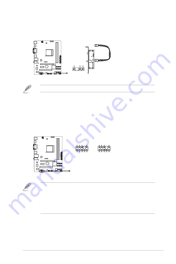
Digital audio connector (4-1 pin SPDIF_OUT)

This connector is for an additional Sony/Philips Digital Interface (S/PDIF) port.

The S/PDIF module is purchased separately.

• 

We recommend that you connect a high-definition front panel audio module to this 

connector to avail of the motherboard high-definition audio capability.

• 

If you want to connect a high definition front panel audio module to this connector, set 

the 

Front Panel Type

 item in the BIOS to 

[HD]

. See section 

2.5.5 Onboard Devices 

Configuration

 for details.

• 

The front panel audio I/O module is purchased separately.

7. 

Front panel audio connector (10-1 pin AAFP)

This connector is for a chassis-mounted front panel audio I/O module that supports 

either High Definition Audio or AC`97 audio standard. Connect one end of the front 

panel audio I/O module cable to this connector.

SPDIF_OUT

+5V

SPDIFOUT GND

A55M-A/USB3

A55M-A/USB3 Digital audio connector

A55M-A/USB3

A55M-A/USB3 Front panel audio connector

AAFP

PIN 1

AGND NC SENSE1_RETUR

SENSE2_RETUR

PORT1 L PORT1 R PORT2 R

SENSE_SEND

PORT2 L

HD-audio-compliant

pin definition

PIN 1

AGND NC NC

NC

MIC2

MICPWR

Line out_R

NC

Line out_L

Legacy AC’97

compliant definition

ASUS A55M-A Series

1-27

Summary of Contents for A55M-A Series

Page 1: ...Motherboard A55M A Series A55M A A55M A USB3 ...

Page 2: ...spective companies and are used only for identification or explanation and to the owners benefit without intent to infringe Offer to Provide Source Code of Certain Software This product contains copyrighted software that is licensed under the General Public License GPL under the Lesser General Public License Version LGPL and or other Free Open Source Software Licenses Such software in this product...

Page 3: ... 1 4 Accelerated Processing Unit APU 1 7 1 4 1 APU installation 1 8 1 4 2 APU heatsink and fan assembly installation 1 9 1 5 System memory 1 11 1 5 1 Overview 1 11 1 5 2 Memory configurations 1 12 1 5 3 Installing a DIMM 1 17 1 6 Expansion slots 1 18 1 6 1 Installing an expansion card 1 18 1 6 2 Configuring an expansion card 1 18 1 6 3 PCI slot 1 18 1 6 4 PCI Express x1 slot 1 18 1 6 5 PCI Express...

Page 4: ...requency Auto 2 13 2 4 5 EPU Power Saving Mode Disabled 2 13 2 4 6 DRAM Timing Control 2 14 2 4 7 APU Voltage Offset Mode 2 14 2 4 8 DRAM Voltage Auto 2 14 2 4 9 SB 1 1V Voltage Auto 2 14 2 4 10 DIGI VRM 2 15 2 5 Advanced menu 2 16 2 5 1 CPU Configuration 2 16 2 5 2 SATA Configuration 2 18 2 5 3 USB Configuration 2 19 2 5 4 NB Configuration 2 19 2 5 5 Onboard Devices Configuration 2 20 2 5 6 APM 2...

Page 5: ...tion ROM Messages Force BIOS 2 27 2 7 7 Interrupt 19 Capture Postponed 2 27 2 7 8 Setup Mode EZ Mode 2 27 2 7 9 CSM Parameters 2 28 2 7 10 Secure Boot 2 28 2 7 11 Boot Option Priorities 2 29 2 7 12 Boot Override 2 29 2 8 Tools menu 2 30 2 8 1 ASUS EZ Flash 2 Utility 2 30 2 8 2 ASUS SPD Information 2 30 2 8 3 ASUS O C Profile 2 30 2 9 Exit menu 2 31 Appendices Notices A 1 ASUS contact information A...

Page 6: ...your area If you are not sure about the voltage of the electrical outlet you are using contact your local power company If the power supply is broken do not try to fix it by yourself Contact a qualified service technician or your retailer Operation safety Before installing the motherboard and adding devices on it carefully read all the manuals that came with the package Before using the product en...

Page 7: ...system settings through the BIOS Setup menus Detailed descriptions of the BIOS parameters are also provided Where to find more information Refer to the following sources for additional information and for product and software updates 1 ASUS websites The ASUS website provides updated information on ASUS hardware and software products Refer to the ASUS contact information 2 Optional documentation Yo...

Page 8: ...lete a task IMPORTANT Instructions that you MUST follow to complete a task NOTE Tips and additional information to help you complete a task Typography Bold text Indicates a menu or an item to select Italics Used to emphasize a word or a phrase Key Keys enclosed in the less than and greater than sign means that you must press the enclosed key Example Enter means that you must press the Enter or Ret...

Page 9: ...D Radeon HD 7000 Series Graphics in the A Series APU Supports HDMI with a maximum resolution of 1920x1080 60Hz Supports Dual link DVI with a maximum resolution of 2560x1600 60Hz Supports D Sub with a maximum resolution of 1920x1600 60Hz AMD Dual Graphics technology support Maximum shared memory of 2GB Supports Microsoft DirectX 11 Refer to http www amd com us products technologies dual graphics Pa...

Page 10: ... port 2 x USB 3 0 ports and 2 x USB 2 0 1 1 ports A55M A USB3 only 4 x USB 2 0 1 1 ports A55M A only 8 channel audio I O ports 3 jack Internal I O connectors buttons switches 2 x USB 2 0 1 1 connectors support additional 4 USB 2 0 1 1 ports 6 x SATA 3 0Gb s connectors 1 x System panel connector 1 x Internal Speaker connector 1 x CPU fan connector 4 pin 1 x S PDIF output connector 1 x Chassis fan c...

Page 11: ...t 240 pin module SATA6G_5 SATA6G_6 SATA6G_3 SATA6G_4 SATA6G_1 SATA6G_2 AUDIO KBMS LAN1_USB12 USB1112 HDMI DVI_VGA SOCKET FM2 DIGI VRM ASUS A55M A Series motherboard 2 x Serial ATA 3 0 Gb s cables UserGuide 1 x I O Shield User Guide Support DVD A55M A Series motherboards include A55M A and A55M A USB3 models The package contents vary from models If any of the above items is damaged or missing conta...

Page 12: ...xii ...

Page 13: ...dia and Internet applications 100 All High quality Conductive Polymer Capacitors This motherboard uses all high quality conductive polymer capacitors for durability improved lifespan and enhanced thermal capacity 1 1 2 ASUS DIGI VRM DIGI POWER CONTROL Digital Power Design for the APU ASUS motherboards using the AMD A55 chipset employ precise digital voltage regulation for the APU called DIGI VRM V...

Page 14: ...for most accessed information ASUS DRAM SPD Serial Presence Detect information detecting faulty DIMMs and helping with difficult POST situations EPU EPU Energy Processing Unit the world s first real time system power saving chip automatically detects the current system load and intelligently moderates power usage It offers a total system wide energy optimization reduces fan noise and extends the c...

Page 15: ...from a USB storage device that contains the BIOS file USB 3 0 Boost A55M A USB3 only With USB 3 0 Boost technology a USB device s transmission speed is significantly increased adding to an already impressive USB 3 0 transfer speed ASUS software automatically accelerates data speeds for compatible USB 3 0 peripherals without the need for any user interaction ASUS A55M A Series 1 3 ...

Page 16: ...grounded antistatic pad or in the bag that came with the component Before you install or remove any component switch off the ATX power supply and detach its power cord Failure to do so may cause severe damage to the motherboard peripherals or components Standby Power LED The motherboard comes with a standby power LED that lights up to indicate that the system is ON in sleep mode or in soft off mod...

Page 17: ...ientation The edge with external ports goes to the rear part of the chassis as indicated in the image below DO NOT overtighten the screws Doing so can damage the motherboard Place this side towards the rear of the chassis 1 3 2 Screw holes Place six screws into the holes indicated by circles to secure the motherboard to the chassis ASUS A55M A Series 1 5 ...

Page 18: ...DR3 DIMM_A1 64bit 240 pin module DDR3 DIMM_B1 64bit 240 pin module SATA6G_5 SATA6G_6 SATA6G_3 SATA6G_4 SATA6G_1 SATA6G_2 AUDIO KBMS LAN1_USB12 USB1112 HDMI 18 8cm 7 4in DVI_VGA SOCKET FM2 DIGI VRM 3 2 1 5 4 6 7 2 8 9 10 11 12 13 14 A55M A Series motherboards include A55M A and A55M A USB3 models The package contents vary between models The layout illustrations in this user guide are for A55M A USB...

Page 19: ...BPWB 1 21 2 ATX power connectors 24 pin EATXPWR 4 pin ATX12V 1 24 3 AMD FM2 socket 1 7 4 CPU fan connector 4 pin CPU_FAN and Chassis fan connector 3 pin CHA_FAN 1 23 5 DDR3 DIMM slots 1 11 6 SATA 3 0Gb s connectors 7 pin SATA3G_1 6 1 25 7 System panel connector 10 1 pin F_PANEL 1 26 8 Speaker connector 4 pin SPEAKER 1 26 9 Clear RTC RAM 3 pin CLRTC 1 20 10 USB 2 0 connectors 10 1 pin USB56 USB34 1...

Page 20: ...1 4 1 APU installation 1 4 3 2 Chapter 1 Product introduction 1 8 ...

Page 21: ...eatsink and fan assembly installation Apply the Thermal Interface Material to the APU heatsink and APU before you install the heatsink and fan if necessary To install the APU heatsink and fan assembly ASUS A55M A Series 1 9 ...

Page 22: ...To uninstall the APU heatsink and fan assembly 5 3 1 4 2 Chapter 1 Product introduction 1 10 ...

Page 23: ...ions as a DDR2 DIMM but is notched differently to prevent installation on a DDR2 DIMM socket DDR3 modules are developed for better performance with less power consumption The figure illustrates the location of the DDR3 DIMM sockets Channel Sockets Channel A DIMM_A1 Channel B DIMM_B1 A55M A USB3 A55M A USB3 240 pin DDR3 DIMM sockets DIMM_A1 DIMM_B1 ASUS A55M A Series 1 11 ...

Page 24: ...rted with 16GB or above DIMMs ASUS will update the memory QVL once the DIMMs are available in the market The default memory operation frequency is dependent on its Serial Presence Detect SPD which is the standard way of accessing information from a memory module Under the default state some memory modules for overclocking may operate at a lower frequency than the vendor marked value To operate at ...

Page 25: ...B 2 x 4GB DS 9 9 9 24 1 65V CORSAIR CMZ8GX3M2A1600C7R XMP 8GB 2 x 4GB DS 7 8 7 20 1 50V CORSAIR CMX8GX3M4A1600C9 XMP 8GB 4 x 2GB DS 9 9 9 24 1 65V Crucial BL25664BN1608 16FF XMP 6GB 3 x 2GB DS G SKILL F3 12800CL7D 4GBECO XMP 4GB 2 x 2GB DS 7 7 8 24 XMP1 35V G SKILL F3 12800CL9D 4GBECO XMP 4GB 2 x 2GB DS 9 9 9 24 XMP1 35V G SKILL F3 12800CL9D 4GBRL XMP 4GB 2 x 2GB DS 9 9 9 24 1 5V G SKILL F3 12800C...

Page 26: ... 24 1 65V Silicon Power SP004GBLTU160V02 XMP 4GB DS S POWER 20YT5NG 1201 DDR3 1600 MHz capability Vendors Part No Size SS DS Chip Brand Chip No Timing Voltage DIMM socket support optional 1DIMM 2DIMMs A DATA AD3U1333C2G9 2GB SS A DATA 3CCD 1509HNA1126L 1 5V A DATA AM2U139C2P1 2GB SS ADATA 3CCD 1509A EL1127T A DATA AX3U1333C2G9 BP 2GB SS A DATA AXDU1333GC2G9 2G XMP 4GB 2x2GB SS 9 9 9 24 1 25V 1 35V...

Page 27: ...D3N9 4G 4GB DS ELPIDA J2108BCSE DJ F 1 5V KINGSTON KVR1333D3N9 4G 4GB DS KTC D2568JENCNGD9U 1 5V KINGSTON KVR1333D3N9 4G 4GB DS Hynix H5TQ2G83AFR KINGSTON KVR1333D3N9 4G SP 4GB DS KINGSTON D2568JENCPGD9U 1 5V Micron MT8JTF25664AZ 1G4D1 2GB SS Micron OJD12D9LGK Micron MT8JTF25664AZ 1G4M1 2GB SS MICRON IJM22 D9PFJ Micron MT16JTF25664AZ 1G4F1 2GB DS Micron 9KF27D9KPT 9 Micron MT16JTF51264AZ 1G4D1 4GB...

Page 28: ...D313332G 2GB DS PATRIOT PM128M8D385 15 Kingtiger 2GB DIMM PC3 10666 2GB DS SAMSUNG SEC 904 HCH9 K4B1G0846D Kingtiger KTG2G1333PG3 2GB DS MARKVISION BMD32048M1333C9 1123 2GB DS MARKVISION M3D1288P 13 MARKVISION BMD34096M1333C9 1124 4GB DS MARKVISION M3D2568E 13 PATRIOT PSD32G13332H 2GB DS PATRIOT PG38G1333EL XMP 8GB DS 9 9 9 24 1 5V RAMAXEL RMR1870ED48E8F 1333 2GB DS ELPIDA J1108BDBG DJ F RAMAXEL R...

Page 29: ...1 5 3 Installing a DIMM 1 2 3 A To remove a DIMM B A ASUS A55M A Series 1 17 ...

Page 30: ...ed earlier 6 Replace the system cover When using PCI cards on shared slots ensure that the drivers support Share IRQ or that the cards do not need IRQ assignments Otherwise conflicts will arise between the two PCI groups making the system unstable and the card inoperable 1 6 3 PCI slot The PCI slot supports cards such as a LAN card SCSI card USB card and other cards that comply with PCI specificat...

Page 31: ... E F G H PCIEx16_1 shared PCIEx1_1 shared PCI1 slot shared Realtek LAN controller shared HD audio shared SATA controller shared On Chip USB EHCI 1 2 3 shared On Chip USB EHCI 1 2 3 4 shared ASM1042 USB3 0 controller shared ASUS A55M A Series 1 19 ...

Page 32: ...2 default to pins 2 3 Keep the cap on pins 2 3 for about 5 10 seconds then move the cap back to pins 1 2 3 Plug the power cord and turn ON the computer 4 Hold down the Del key during the boot process and enter BIOS setup to reenter data If the steps above do not help remove the onboard battery and move the jumper again to clear the CMOS RTC RAM data After clearing the CMOS reinstall the battery Yo...

Page 33: ... power up The total current consumed must NOT exceed the power supply capability 5VSB whether under normal condition or in sleep mode A55M A USB3 A55M A USB3 USB device wake up 2 1 2 3 5V Default 5VSB USBPWF 2 Keyboard power 3 pin KB_USBPWB This jumper allows you to enable or disable the keyboard wake up feature When you set this jumper to pins 2 3 5VSB you can wake up the computer by pressing a k...

Page 34: ...io sources 5 Line Out port lime This port connects to a headphone or a speaker In the 4 6 and 8 channel configurations the function of this port becomes Front Speaker Out 6 Microphone port pink This port connects to a microphone Refer to the audio configuration table below for the function of the audio ports in 2 4 6 or 8 channel configuration Audio 2 4 6 or 8 channel configuration Port Headset 2 ...

Page 35: ...Blu ray and other protected content 11 PS 2 Keyboard port purple This port is for a PS 2 keyboard 1 8 2 Internal connectors 1 CPU and chassis fan connectors 4 pin CPU_FAN and 3 pin CHA_FAN Connect the fan cables to the fan connectors on the motherboard ensuring that the black wire of each cable matches the ground pin of the connector The CPU_FAN connector supports a CPU fan of maximum 2A 24 W fan ...

Page 36: ...he power is inadequate DO NOT forget to connect the 4 pin ATX 12V power plug Otherwise the system will not boot up We recommend that you use a PSU with higher power output when configuring a system with more power consuming devices or when you intend to install additional devices The system may become unstable or may not boot up if the power is inadequate If you are uncertain about the minimum pow...

Page 37: ...ice Pack 3 or later version before using Serial ATA hard disk drives The Serial ATA RAID feature is available only if you are using Windows XP SP3 or later version When using hot plug and NCQ set the type of the SATA connectors in the BIOS to AHCI See section 2 5 2 SATA Configuration for details SATA3G_6 GND RSATA_TXP5 RSATA_TXN5 GND RSATA_RXN5 RSATA_RXP5 GND GND RSATA_RXP1 RSATA_RXN1 GND RSATA_TX...

Page 38: ... flashes when data is read from or written to the HDD ATX power button soft off button 2 pin PWRBTN This 2 pin connector is for the system power button Reset button 2 pin RESET This 2 pin connector is for the chassis mounted reset button for system reboot without turning off the system power 5 Speaker connector 4 pin SPEAKER The 4 pin connector is for the chassis mounted system warning speaker The...

Page 39: ...ation for details The front panel audio I O module is purchased separately 7 Front panel audio connector 10 1 pin AAFP This connector is for a chassis mounted front panel audio I O module that supports either High Definition Audio or AC 97 audio standard Connect one end of the front panel audio I O module cable to this connector SPDIF_OUT 5V SPDIFOUT GND A55M A USB3 A55M A USB3 Digital audio conne...

Page 40: ...onnectors comply with USB 2 0 specification that supports up to 480Mbps connection speed Never connect a 1394 cable to the USB connectors Doing so will damage the motherboard The USB 2 0 module is purchased separately A55M A USB3 A55M A USB3 USB2 0 connectors PIN 1 USB 5V USB_P6 USB_P6 GND NC USB 5V USB_P5 USB_P5 GND USB56 USB34 PIN 1 USB 5V USB_P4 USB_P4 GND NC USB 5V USB_P3 USB_P3 GND Chapter 1 ...

Page 41: ...es with the motherboard package contains the drivers software applications and utilities that you can install to avail all motherboard features The contents of the Support DVD are subject to change at any time without notice Visit the ASUS website at www asus com for updates To run the Support DVD Place the Support DVD into the optical drive If Autorun is enabled in your computer the DVD automatic...

Page 42: ...Chapter 1 Product introduction 1 30 ...

Page 43: ...rt DVD that comes with the motherboard package Installing ASUS Update To install ASUS Update 1 Place the support DVD in the optical drive The Specials menu appears 2 Click the Utilities tab then click AI Suite II 3 Follow the onscreen instructions to complete the installation Quit all Windows applications before you update the BIOS using this utility Updating the BIOS To update the BIOS 1 From the...

Page 44: ...ased utility Before you start using this utility download the latest BIOS file from the ASUS website at www asus com To update the BIOS using EZ Flash 2 1 Insert the USB flash disk that contains the latest BIOS file to the USB port 2 Enter the Advanced Mode of the BIOS setup program Go to the Tool menu to select ASUS EZ Flash 2 Utility and press Enter to enable it 3 Press Tab to switch to the Driv...

Page 45: ... DVD may not be the latest version Download the latest BIOS file from the ASUS website at www asus com Recovering the BIOS To recover the BIOS 1 Turn on the system 2 Insert the support DVD to the optical drive or the USB flash drive that contains the BIOS file to the USB port 3 The utility automatically checks the devices for the BIOS file When found the utility reads the BIOS file and enters ASUS...

Page 46: ...cess The succeeding utility screens are for reference only The actual utility screen displays may not be same as shown Before updating BIOS 1 Prepare the motherboard support DVD and a USB flash drive formatted using FAT32 16 on a single partition 2 Download the latest BIOS file and BIOS Updater from the ASUS website at http support asus com and save them on the USB flash drive NTFS is not supporte...

Page 47: ...e End keys to select the BIOS file and press Enter BIOS Updater checks the selected BIOS file and prompts you to confirm BIOS update Are you sure to update BIOS Yes No 4 Select Yes and press Enter When BIOS update is done press ESC to exit BIOS Updater Restart your computer DO NOT shut down or reset the system while updating the BIOS to prevent system boot failure For BIOS Updater version 1 30 or ...

Page 48: ...BIOS Setup using the first two options The BIOS setup screens shown in this section are for reference purposes only and may not exactly match what you see on your screen Ensure that a USB mouse is connected to your motherboard if you want to use the mouse to control the BIOS setup program The default BIOS settings for this motherboard apply for most conditions to ensure optimum performance If the ...

Page 49: ...enu for details The boot device options vary depending on the devices you installed to the system The Boot Menu F8 button is available only when the boot device is installed to the system Exits the BIOS setup program without saving the changes saves the changes and resets the system or enters the Advanced Mode Selects the display language of the BIOS setup program Displays the CPU motherboard temp...

Page 50: ...the screen has the following main items Main For changing the basic system configuration Ai Tweaker For changing the overclocking settings Advanced For changing the advanced system settings Monitor For displaying the system temperature power status and changing the fan settings Boot For changing the system boot configuration Tool For configuring options for special functions Exit For selecting the...

Page 51: ...configuration options for that item Scroll bar A scroll bar appears on the right side of a menu screen when there are items that do not fit on the screen Press the Up Down arrow keys or Page Up Page Down keys to display the other items on the screen Navigation keys At the bottom right corner of the menu screen are the navigation keys for the BIOS setup program Use the navigation keys to select ite...

Page 52: ...tions English Français Español Deutsch Русский 2 3 2 System Date Day xx xx xxxx Allows you to set the system date 2 3 3 System Time xx xx xx Allows you to set the system time 2 3 4 Security The Security menu items allow you to change the system security settings If you have forgotten your BIOS password erase the CMOS Real Time Clock RTC RAM to clear the BIOS password See section 1 7 Jumpers for in...

Page 53: ...Enter when prompted to create confirm the password After you clear the password the Administrator Password item on top of the screen shows Not Installed User Password If you have set a user password you must enter the user password for accessing the system The User Password item on top of the screen shows the default Not Installed After you set a password this item shows Installed To set a user pa...

Page 54: ...ing related items Be cautious when changing the settings of the Ai Tweaker menu items Incorrect field values can cause the system to malfunction The configuration options for this section vary depending on the CPU and DIMM model you installed on the motherboard Scroll down to display the following items ...

Page 55: ...uency Configuration options Auto DDR3 800MHz DDR3 1066MHz DDR3 1333MHz DDR3 1600MHz DDR3 1866MHz Selecting a very high memory frequency may cause the system to become unstable If this happens revert to the default setting 2 4 3 APU Multiplier Auto Allows you to set the multiplier between the CPU Core Clock and the FSB Frequency Use the and keys to adjust the ratio The valid value ranges vary accor...

Page 56: ...umentation before setting the CPU voltage Setting a high voltage may damage the CPU permanently and setting a low voltage may make the system unstable VDDNB Offset Mode Sign To offset the voltage by a positive value To offset the voltage by a negative value VDDNB Offset Voltage Auto Allows you to set the VDDNB Offset voltage The values range from 0 00625V to 0 500V with a 0 00625V interval 2 4 8 D...

Page 57: ...nt Capability 100 This item provides wider total power range for overclocking A higher value brings a wider total power range and extends the overclocking frequency range simultaneously Configuration options 100 110 120 130 CPU Power Phase Control Standard Phase number is the number of working VRM phase Increasing phase number under heavy system loading to get more transient and better thermal per...

Page 58: ... The items in this menu show the CPU related information that the BIOS automatically detects The items shown in submenu may be different due to the CPU you installed AMD PowerNow function Enabled Enables or disables the AMD PowerNow function Configuration options Enabled Disabled NX Mode Enabled Enables or disables the No execute page protection function Configuration options Enabled Disabled SVM ...

Page 59: ...m to Enabled to show IOMMU Mode Configuration options Enabled Disabled Bank Interleaving Enabled Enables or disables Bank Interleaving Configuration options Enabled Disabled Channel Interleaving Enabled Enables or disables Channel Interleaving Configuration options Enabled Disabled Core Leveling Mode Automatic mode Adjust ratio of number of cores per processor or per compute unit Configuration opt...

Page 60: ...al storage devices RAID Set to RAID when you want to create a RAID configuration from the SATA hard disk drives AHCI Set to AHCI when you want the SATA hard disk drives to use the AHCI Advanced Host Controller Interface The AHCI allows the onboard storage driver to enable advanced Serial ATA features that increases storage performance on random workloads by allowing the drive to internally optimiz...

Page 61: ...SB support is disabled Legacy USB3 0 Support Enabled A55M A USB3 only Enabled Enables the support for USB 3 0 devices on legacy operating systems OS Disabled Disables the function EHCI Hand off Disabled Enabled Enables the support for operating systems without an EHCI hand off feature Disabled Disables the function USB Single Port Control Allows you to enable disable individual USB ports 2 5 4 NB ...

Page 62: ...ut Type SPDIF SPDIF Sets to SPDIF for SPDIF audio output HDMI Sets to HDMI for HDMI audio output Realtek LAN Controller Enabled Enabled Enables the Realtek LAN controller Disabled Disables the controller Realtek PXE OPROM Disabled This item appears only when you set the Realtek LAN Controller item to Enabled and allows you to enable or disable the Rom Help of the Realtek LAN controller Configurati...

Page 63: ...stem through a PCI PCIE LAN or modem card This feature requires an ATX power supply that provides at least 1A on the 5VSB lead Power On By RTC Disabled Disabled Disables RTC to generate a wake event Enabled When set to Enabled the items RTC Alarm Date Days and Hour Minute Second will become user configurable with set values RTC Alarm Date Days This item appears only when you set the previous item ...

Page 64: ...abled This item appears only when you set the Network Stack item to Enabled When this item is disabled the IPV4 PXE boot option will not be created Configuration options Disabled Enabled Ipv6 PXE Support Enabled This item appears only when you set the Network Stack item to Enabled When this item is disabled the IPV6 PXE boot option will not be created Configuration options Disabled Enabled ...

Page 65: ...RPM or Ignore N A The onboard hardware monitor automatically detects and displays the CPU chassis fan speeds in rotations per minute RPM If the fan is not connected to the motherboard the field shows N A Select Ignore if you do not wish to display the detected speed 2 6 3 CPU Voltage 3 3V Voltage 5V Voltage 12V Voltage The onboard hardware monitor automatically detects the voltage output through t...

Page 66: ...eed control parameters The following four items appear only when you set CPU Profile to Manual CPU_FAN Upper Temperature 70ºC Use the and keys to adjust the upper limit of the CPU temperature The values range from 20ºC to 90ºC CPU_FAN Fan Max Duty Cycle 100 Use the and keys to adjust the maximum CPU fan duty cycle The values range from 40 to 100 When the CPU temperature reaches the upper limit the...

Page 67: ...Chapter 2 BIOS information 2 25 2 7 Boot menu The Boot menu items allow you to change the system boot options Scroll down to display the following items ...

Page 68: ...ices are available during POST This setting will extend POST time Disabled For a shorter POST time all PS 2 devices are available only after the PC enters the OS Network Stack Driver Support Disabled Disabled If Disabled the Network Stack Driver will be skipped To enable this feature enable the Network Stack item in the Advanced menu Enabled Allows the BIOS to boot from the Network Stack Driver Ne...

Page 69: ...pressed when error occurs Configuration options Disabled Enabled 2 7 6 Option ROM Messages Force BIOS Force BIOS The third party ROM messages will be forced to display during the boot sequence Keep Current The third party ROM messages will be displayed only if the third party manufacturer had set the add on device to do so 2 7 7 Interrupt 19 Capture Postponed Immediate Immediately capture Interrup...

Page 70: ...tions Ok Delete the PK Configuration options Yes No 2 7 9 CSM Parameters This option controls whether or not CSM Compatibility Support Module will be launched Launch CSM Auto Configuration option Auto Enabled Disabled The following four items appear only when you set Launch CSM to Enabled Boot Device Control UEFI and Legacy OpROM Configuration option UEFI and Legacy OpRom Legacy OpROM only UEFI on...

Page 71: ...guration options Ok Delete the DBX Configuration options Yes No Append DBX from File Configuration options Ok 2 7 11 Boot Option Priorities These items specify the boot device priority sequence from the available devices The number of device items that appears on the screen depends on the number of devices installed in the system To select the boot device during system startup press F8 when ASUS L...

Page 72: ...ile Save to Profile Allows you to save the current BIOS settings to the BIOS Flash and create a profile Key in a profile number from one to eight press Enter and then select Yes Load from Profile Allows you to load the previous BIOS settings saved in the BIOS Flash Key in the profile number that saved your CMOS settings press Enter and then select Yes DO NOT shut down or reset the system while upd...

Page 73: ...are finished making your selections choose this option from the Exit menu to ensure the values you selected are saved When you select this option or if you press F10 a confirmation window appears Select Yes to save changes and exit Discard Changes Exit This option allows you to exit the Setup program without saving your changes When you select this option or if you press Esc a confirmation window ...

Page 74: ...2 32 ASUS A55M A Series ...

Page 75: ...uit different from that to which the receiver is connected Consult the dealer or an experienced radio TV technician for help The use of shielded cables for connection of the monitor to the graphics card is required to assure compliance with FCC regulations Changes or modifications to this unit not expressly approved by the party responsible for compliance could void the user s authority to operate...

Page 76: ...waste This product has been designed to enable proper reuse of parts and recycling This symbol of the crossed out wheeled bin indicates that the product electrical and electronic equipment should not be placed in municipal waste Check local regulations for disposal of electronic products DO NOT throw the mercury containing button cell battery in municipal waste This symbol of the crossed out wheel...

Page 77: ...chnical Support Telephone 1 812 282 2787 Support fax 1 812 284 0883 Online support support asus com ASUS COMPUTER GmbH Germany and Austria Address Harkort Str 21 23 D 40880 Ratingen Germany Fax 49 2102 959911 Web site www asus de Online contact www asus de sales Technical Support Telephone 49 1805 010923 Support Fax 49 2102 9599 11 Online support support asus com EUR 0 14 minute from a German fixe...

Page 78: ... A55M A USB3 A55M A conform with the essential requirements of the following directives 2004 108 EC EMC Directive EN 55022 2010 EN 61000 3 2 2006 A2 2009 EN 55013 2001 A1 2003 A2 2006 EN 55024 2010 EN 61000 3 3 2008 EN 55020 2007 A11 2011 1999 5 EC R TTE Directive EN 300 328 V1 7 1 2006 10 EN 300 440 1 V1 6 1 2010 08 EN 300 440 2 V1 4 1 2010 08 EN 301 511 V9 0 2 2003 03 EN 301 908 1 V5 2 1 2011 05...

Reviews: