background image

xi

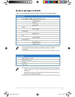
System package contents

Check your A500/AS-D920, BA5190 system package for the following items.

If any of the above items is damaged or missing, contact your retailer 

immediately.

Optional items

1. 

Optical disk drive (ODD)

2. 

Storage card reader

3. 

LAN cable

4. 

Power strip

•  Optional items are not included in the system package. They are purchased 

separately.

•  Specifications depend on the desktop PC you purchased. Check with your 

supplier for the exact specifications.

Standard items

1. 

ASUS A500/AS

-D920, 

BA5190 Desktop PC with


• 

ASUS Desktop x1


• 

Mouse x1


• 

Keyboard x1

2. 

Cables


• 

Power cord x1

3. 

Accessories


• 

Mouse pad x1

4. 

DVD


• 

Support DVD x1

5. 

Documentation


• 

User Manual x1


• 

Warranty card x1

A500 AS-D920.indb   11

4/12/10   5:52:18 PM

Summary of Contents for A500

Page 1: ...A500 AS D920 BA5190 ASUS PC User Manual A500 AS D920 BA5190 A500 AS D920 indb 1 4 12 10 5 52 03 PM ...

Page 2: ...O EVENT SHALL ASUS ITS DIRECTORS OFFICERS EMPLOYEES OR AGENTS BE LIABLE FOR ANY INDIRECT SPECIAL INCIDENTAL OR CONSEQUENTIAL DAMAGES INCLUDING DAMAGES FOR LOSS OF PROFITS LOSS OF BUSINESS LOSS OF USE OR DATA INTERRUPTION OF BUSINESS AND THE LIKE EVEN IF ASUS HAS BEEN ADVISED OF THE POSSIBILITY OF SUCH DAMAGES ARISING FROM ANY DEFECT OR ERROR IN THIS MANUAL OR PRODUCT SPECIFICATIONS AND INFORMATION...

Page 3: ...1 510 608 4555 Web site usa asus com Technical Support Telephone 1 812 282 2787 Support fax 1 812 284 0883 Online support support asus com ASUS Computer GmbH Germany and Austria Address Harkort Str 21 23 D 40880 Ratingen Germany Fax 49 2102 959911 Web site www asus de Online contact www asus de sales Technical Support Telephone Component 49 1805 010923 Telephone System Notebook Eee LCD 49 1805 010...

Page 4: ... 2 3 Support DVD information 2 3 2 3 1 Running the Support DVD 2 3 2 3 2 Drivers menu 2 4 2 3 3 Utilities menu 2 5 2 3 4 Make disk menu 2 6 2 3 5 Manual menu 2 7 2 3 6 ASUS contact information 2 7 2 3 7 Other information 2 8 2 4 ASUS AI Manager 2 10 2 4 1 Installing AI Manager 2 10 2 4 2 Launching AI Manager 2 10 2 4 3 AI Manager Quick Bar 2 10 2 4 4 Main 2 11 2 4 5 My favorites 2 15 2 4 6 Support...

Page 5: ...2 10 Creating a RAID driver disk 2 52 2 10 1 Creating a RAID driver disk without entering the OS 2 52 2 10 2 Creating a RAID driver disk in Windows 2 52 2 11 Loading the initial OS default settings 2 54 2 12 Recovery DVD 2 54 2 12 1 Recovering a Windows XP OS 2 54 2 12 2 Recovering a Windows Vista OS 2 55 2 12 3 Recovering a Windows 7 OS 2 56 A500 AS D920 indb 5 4 12 10 5 52 08 PM ...

Page 6: ...aged to try to correct the interference by one or more of the following measures Reorient or relocate the receiving antenna Increase the separation between the equipment and receiver Connect the equipment to an outlet on a circuit different from that to which the receiver is connected Consult the dealer or an experienced radio TV technician for help Canadian Department of Communications Statement ...

Page 7: ...sachgemäßen Austausch der Batterie Ersatz nur durch denselben oder einem vom Hersteller empfohlenem ähnljchen Typ Entsorgung gebrauchter Batterien nach Angaben des Herstellers LASER PRODUCT WARNING CLASS 1 LASER PRODUCT Operation safety Before installing devices into the system carefully read all the documentation that comes with the package Before using the product ensure that all cables are corr...

Page 8: ... a long time avoid direct contact with the heatsinks and the surfaces of IC as they may become very warm and hot Check if the system receives proper ventilation Before you add or remove a peripheral device to or from the system ensure that you unplugged the system from the power source If the power supply is broken do not try to fix it by yourself Contact a qualified service technician or your ret...

Page 9: ...ists the system features including introduction on the front and rear panels Chapter 2 Getting started This chapter helps you power up the system and install drivers and utilities from the Support DVD Audience This guide provides general information about ASUS A500 AS D920 BA5190 Desktop PC and instructions on how to use the Support DVD that comes with the system package A500 AS D920 indb 9 4 12 1...

Page 10: ...NOTE Tips and additional information to aid in completing a task Where to find more information Refer to the following sources for additional information and for product and software updates 1 ASUS Websites The ASUS websites worldwide provide updated information on ASUS hardware and software products Refer to the ASUS contact information 2 Optional Documentation Your product package may include op...

Page 11: ...Power strip Optional items are not included in the system package They are purchased separately Specifications depend on the desktop PC you purchased Check with your supplier for the exact specifications Standard items 1 ASUS A500 AS D920 BA5190 Desktop PC with ASUS Desktop x1 Mouse x1 Keyboard x1 2 Cables Power cord x1 3 Accessories Mouse pad x1 4 DVD Support DVD x1 5 Documentation User Manual x1...

Page 12: ...1 System introduction This chapter gives a general description of the desktop PC The chapter lists the system features including introduction on the front and rear panels A500 AS D920 indb 1 4 12 10 5 52 18 PM ...

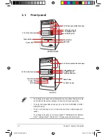
Page 13: ...e card reader The storage card reader is for Secure Digital MultimediaCard Memory Stick CompactFlash Microdrive storage cards and smart cards 3 x 5 25 inch optical disk drive bays HDD LED 2 x USB 2 0 ports 1 x Headphone port 1 x Microphone port Power LED 2 x 3 5 inch drive bays Power button Reset button 2 x USB 2 0 ports A500 AS D920 BA5190 3 x 5 25 inch optical disk drive bays Power LED 4 x USB 2...

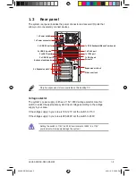
Page 14: ...on slots Air vents 1 x RJ 45 port 2 x USB 2 0 ports Side cover lock 1 x RJ 45 port Only five expansion slots are available on this desktop PC Voltage selector The system s power supply unit has a 115V 230V voltage selector Use this switch to select the appropriate system input voltage according to the voltage supply in your area If the voltage supply in your area is 100 127V set the switch to 115V...

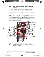
Page 15: ...nnecting to other peripheral devices The ASUS A500 AS D920 and BA5190 Desktop PC is equipped with a number of ports at the rear and front panels where you can connect peripheral devices to the system Refer to the illustration below for details Before you connect a peripheral device to the system refer to the documentation that comes with the device or contact your supplier directly for information...

Page 16: ...Chapter 2 Getting started This chapter helps you to power up the system and install drivers and utilities from the Support DVD A500 AS D920 indb 1 4 12 10 5 52 49 PM ...

Page 17: ...ivers that come with the OS Select NO when a window appears asking if you want to restart the system Install drivers according to the instructions in the following sections 2 2 Powering your system Press the Power button to power up the system To ensure that the OS works properly install the drivers included in the Support DVD Motherboard settings and hardware options vary Use the setup procedures...

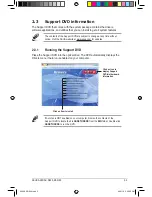
Page 18: ... The DVD automatically displays the Drivers menu if Autorun is enabled on your computer Click an icon to display Support DVD motherboard information 2 3 Support DVD information The Support DVD that comes with the system package contains the drivers software applications and utilities that you can install to get all system features The contents of the Support DVD are subject to change at any time w...

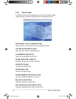
Page 19: ...talls the Intel chipset Inf update program SoundMAX ADI Audio Driver Installs the SoundMAX ADI audio driver Realtek RTL8111B C LAN Driver Installs the Realtek RTL8111B C LAN driver ASUS EPU 6 Engine Installs ASUS EPU 6 Engine ASUS Express Gate Installs ASUS Express Gate NVIDIA EN9500GT VGA Driver Program Installs the NVIDIA EN9500GT VGA driver Marvell 61xx SATA Driver Installs the Marvell 61xx SAT...

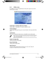
Page 20: ...an launch AI Disk AI Security and AI Probe easily ASUS Update Allows you to download the latest version of the BIOS from the ASUS website Realtek Teaming Utility Installs the Realtek Teaming Utility Marvell RAID Utility Installs the Marvell RAID utility Adobe Reader 8 Installs the Adobe Acrobat Reader that allows you to open view and print documents in Portable Document Format PDF Before using the...

Page 21: ... 64 bit AHCI RAID Driver Allows you to create an Intel ICH10R Serial ATA SATA AHCI RAID driver disk for 64bit XP Vista operating systems Marvell 61xx 32 64bit SATA RAID Driver Allows you to create a Marvell 61xx Serial ATA SATA RAID driver disk for 32 64bit XP Vista operating systems Marvell 64xx 63xx SAS Controller Driver Allows you to create a Marvell 64xx 63xx SAS controller driver disk for 32 ...

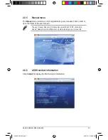
Page 22: ...n 2 3 5 Manual menu The Manual menu contains a list of supplementary user manuals Click an item to open the folder of the user manual The user manual files are in Portable Document Format PDF Install the Adobe Reader from the Utilities menu before opening a user manual file A500 AS D920 indb 7 4 12 10 5 52 58 PM ...

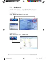
Page 23: ...additional information on the motherboard and the contents of the Support DVD Click an icon to display the specified information Motherboard Info Displays the general specifications of the motherboard Browse this DVD Displays the Support DVD contents in graphical format A500 AS D920 indb 8 4 12 10 5 53 00 PM ...

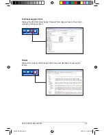
Page 24: ...Form Displays the ASUS Technical Support Request Form that you have to fill out when requesting technical support Filelist Displays the contents of the Support DVD and a brief description of each in text format A500 AS D920 indb 9 4 12 10 5 53 03 PM ...

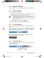
Page 25: ...ities tab then click ASUS AI Manager 3 Follow the onscreen instructions to complete the installation 2 4 2 Launching AI Manager You can launch AI Manager right after installation or anytime from the Windows desktop To launch AI Manager from the Windows desktop click Start All Programs ASUS AI Manager AI Manager v1 xx xx The AI Manager Quick Bar appears After launching the application the AI Manage...

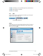
Page 26: ...nch AI Disk AI Security and AI Probe from the Main menu Click the small triangle to open or close the Main menu Click to open close the Main menu AI Disk AI Disk allows you to easily clear the temporary IE files IE URLs IE cookies IE history list Recycle Bin and recently opened files list Select the item that you want to clear then click Apply A500 AS D920 indb 11 4 12 10 5 53 07 PM ...

Page 27: ...ch as a USB flash disk and a CD DVD disk which ensures more security for your data To lock a device 1 If you are using AI Security for the first time key in a password consisting of up to 20 alphanumeric characters 2 Confirm your password 3 Key in your password hint optional 4 Click OK A500 AS D920 indb 12 4 12 10 5 53 08 PM ...

Page 28: ...sed without the password To unlock a device 1 Deselect the device you locked then click Apply 2 Key in your password then click OK To change your password click Change Password and follow the onscreen instructions 5 Select the device you want to lock then click Apply A500 AS D920 indb 13 4 12 10 5 53 09 PM ...

Page 29: ...2 Getting started AI Probe AI Probe automatically detects the motherboard and CPU temperatures CPU fan speed and CPU voltage It also allows you to adjust these values manually A500 AS D920 indb 14 4 12 10 5 53 10 PM ...

Page 30: ...he succeeding screen select the application you want to add to the My Favorites menu 2 Click Open The application you selected is added and its icon appears Right click an icon in the My Favorites menu to open delete or rename the corresponding application Double click an icon to open the corresponding application A500 AS D920 indb 15 4 12 10 5 53 11 PM ...

Page 31: ...national website online technical support website online download support website and contact information website 2 4 7 Information The Information menu displays the general information of your system motherboard CPU BIOS memory and other devices installed A500 AS D920 indb 16 4 12 10 5 53 13 PM ...

Page 32: ...eplace the system boot logo before flashing BIOS and then click Next 4 Select Update BIOS from a file from the drop down menu and then click Next 5 Locate the new BIOS file and then click Next The ASUS MyLogo 2 window appears 6 From the left window pane select the folder that contains the image you intend to use as your boot logo Before using ASUS MyLogo 2 use the ASUS Update or AFUDOS utilities t...

Page 33: ...o 10 After flashing the BIOS restart the computer to display the new boot logo during POST 8 Adjust the boot image to your desired size by selecting a value on the Ratio box Click Next 7 When the logo images appear on the right window pane select an image to enlarge by clicking on it A500 AS D920 indb 18 4 12 10 5 53 15 PM ...

Page 34: ... 6 Engine on your computer 1 Place the Support DVD into the optical drive The Drivers menu appears if Autorun is enabled on your computer 2 Click the Drivers tab and then click ASUS EPU 6 Engine 3 Follow the onscreen instructions to complete the installation Launching 6 Engine Launch 6 Engine by double clicking the 6 Engine icon in the Windows system tray The first time you launch 6 Engine the fol...

Page 35: ...ing Mode Max Power Saving Mode Advanced settings for each mode refer to the next page for further information Displays CPU Power and Total CPU Energy Saving Shifts between the display of Total and Current CO2 reduced Displays the amount of CO2 reduced Displays the following message if no VGA power saving engine is detected Exits the utility Displays the system properties of each mode Displays curr...

Page 36: ...tage High Downgrades voltage to the highest level for CPU power saving Small Downgrades voltage to the minimum level Chipset Voltage Downgrade Turns on off chipset voltage Turn Off hard disks Turns off hard disk drives when they are not accessed after a certain time CPU Loadline Sets up the CPU loadline to manage CPU power saving Light Saves CPU power to the minimum level Heavy Saves CPU power to ...

Page 37: ... Fan Control N A N A Keep Bios Setting Slow Keep Bios Setting Quiet AI Nap Idle Time Never After 3 mins After 5 hours Never After 3 mins After 5 hours Never After 3 mins After 5 hours Never After 3 mins After 5 hours Refer to the following table for the configuration options in each mode Fan Control Adjusts fan speeds to reduce noise and save system power Quiet Lowers CPU fan speed and shuts off t...

Page 38: ... ASUS Express Gate supports SATA devices in IDE mode only ASUS Express Gate supports SATA devices connected to motherboard chipset controlled onboard SATA ports only All onboard extended SATA ports and external SATA ports are NOT supported See section 1 2 1 Motherboard layout for the exact location of the onboard SATA ports Ensure that your monitor supports the screen resolution of 1024 x 768 befo...

Page 39: ...boot time depends on the system configuration To enter the motherboard BIOS Setup program click Exit on the splash screen and then hold down Del during POST Click in the Express Gate environment for the detailed software instructions Click an application icon to enter the Express Gate environment and launch the selected application Turn off the computer Continue booting to the existing OS when the...

Page 40: ...s The LaunchBar can be configured to auto hide and dock at the bottom or top of the screen The indicator under an application icon indicates that the application is running If an application stops responding right click its icon then select Close to force it to close Launches the Online Games Launches the Photo Manager Launches the Chat instant messaging tool Launches the Skype application which a...

Page 41: ...lick this icon to launch the File Manager window Right click it to eject the removable storage device USB drive Exits ASUS Express Gate Click Yes to enter the operating system you installed on the hard disk drive Powers off the computer Accessing the Internet To configure the network settings 1 Click Configuration Panel on the LaunchBar 2 Click Network 3 Make the proper network configurations Each...

Page 42: ...erent port while Express Gate is running e g move the cable from LAN1 to LAN2 restart Express Gate to activate the new setting WiFi settings if supported If you want to connect to a wireless network click Setup to configure the WiFi options In the WiFi tab of the Advanced Network Settings box key in the network name of the wireless access point in the SSID field If Security is enabled on the wirel...

Page 43: ...supported Using the Online Games Express Gate introduces a Splashtop Gaming portal site which provides interesting games in different categories Enable the Internet connection to use the Online Games feature Restoring to factory settings To restore Express Gate to the factory settings 1 Click Configuration Panel on the LaunchBar 2 Click Environment Settings 3 Click Restore from the General tab A c...

Page 44: ...tall the software or use the repair utility to repair Express Gate To repair Express Gate Click Start All Programs Express Gate Express Gate Installer Repair this software then follow the onscreen instructions to complete the repair ASUS EZ Flash 2 Express Gate Auto Enter OS Timer 10 Seconds Reset User Data No BIOS SETUP UTILITY Main Advanced Power Boot Tools Exit Press ENTER to run the utility to...

Page 45: ...the teaming set Click OK to finish the teaming setting 2 8 Realtek Teaming Utility This motherboard features two Realtek 8111C PCIe Gigabit LAN controllers and supports Teaming function which allows two single connections to be grouped as one single connection providing benefits such as bandwidth increase load balancing and fault tolerance The speed of transmission is subject to the actual network...

Page 46: ...aunch the Realtek VLAN Teaming Utility by clicking Start All Programs Realtek Teaming and VLAN Utility Realtek Teaming and VLAN Utility 2 Choose the adapters to join the teaming set and then select a teaming mode that best suits your network environment Click Teaming to create the teaming set Click OK to close the message windows and finish creating the teaming set To remove a teaming set in Windo...

Page 47: ... VLAN Click OK to close the message window and finish creating the virtual LAN adapter 3 Click Start Control Panel Network and Sharing Center and then click Manage network connections from the left Tasks list Right click the virtual LAN adapter icon and select Properties 4 Conduct necessary settings for the virtual LAN adapter and then click Configure A500 AS D920 indb 32 4 12 10 5 53 42 PM ...

Page 48: ...r for VLAN NDIS 6 0 Properties window and conduct necessary VLAN settings Close all windows when finished To remove a virtual LAN adapter in Windows Vista 1 Launch the Realtek VLAN Teaming Utility 2 Click Remove to remove the existing virtual LAN adapter A500 AS D920 indb 33 4 12 10 5 53 42 PM ...

Page 49: ...ses fault tolerance to the entire system Use two new drives or use an existing drive and a new drive for this setup The new drive must be of the same size or larger than the existing drive RAID 5 stripes both data and parity information across three or more hard disk drives Among the advantages of RAID 5 configuration include better HDD performance fault tolerance and higher storage capacity The R...

Page 50: ...2 Go to Main Storage Configuration Configure SATA as then press Enter 3 Select RAID then press Enter 5 Save your changes then exit the BIOS Setup 2 9 2 Installing Serial ATA hard disks The motherboard supports Serial ATA hard disk drives For optimal performance install identical drives of the same model and capacity when creating a disk array To install the SATA hard disks for a RAID configuration...

Page 51: ...10R wRAID5 Copyright C 2003 08 Intel Corporation All Rights Reserved MAIN MENU 1 Create RAID Volume 3 Reset Disks to Non RAID 2 Delete RAID Volume 4 Exit DISK VOLUME INFORMATION RAID Volumes None defined Physical Disks Port Drive Model Serial Size Type Status Vol ID 0 XXXXXXXXXXX XXXXXXXX XX XXGB Non RAID Disk 1 XXXXXXXXXXX XXXXXXXX XX XXGB Non RAID Disk 2 XXXXXXXXXXX XXXXXXXX XX XXGB Non RAID Dis...

Page 52: ... Reserved CREATE VOLUME MENU HELP Enter a unique volume name that has no special characters and is 16 characters or less Change TAB Next ESC Previous Menu Enter Select Name RAID Level Disks Strip Size Capacity Volume0 RAID0 Stripe Select Disks 128KB XXX GB Create Volume SELECT DISKS Previous Next SPACE SelectsDisk ENTER Done Port Drive Model Serial Size Status 0 XXXXXXXXXXXX XXXXXXXX XX XGB Non RA...

Page 53: ...ant to create this volume Y N 9 Press Y to create the RAID volume and return to the main menu or N to go back to the Create Volume menu 6 Use the up down arrow key to select the stripe size for the RAID 0 array and then press Enter The available stripe size values range from 4 KB to 128 KB The default stripe size is 128 KB We recommend a lower stripe size for server systems and a higher stripe siz...

Page 54: ... Press Enter when the Create Volume item is highlighted The following warning message appears WARNING ALL DATA ON SELECTED DISKS WILL BE LOST Are you sure you want to create this volume Y N 6 Press Y to create the RAID volume and return to main menu or N to go back to Create Volume menu Intel R Matrix Storage Manager option ROM v8 0 0 1027 ICH10R wRAID5 Copyright C 2003 08 Intel Corporation All Ri...

Page 55: ...4 KB to 64 KB The default stripe size is 64 KB Intel R Matrix Storage Manager option ROM v8 0 0 1027 ICH10R wRAID5 Copyright C 2003 08 Intel Corporation All Rights Reserved CREATE VOLUME MENU HELP Enter a unique volume name that has no special characters and is 16 characters or less Change TAB Next ESC Previous Menu Enter Select Name RAID Level Disks Strip Size Capacity Volume10 RAID10 RAID0 1 Sel...

Page 56: ...lighted The following warning message appears 2 Enter a name for the RAID 5 set and press Enter 3 When the RAID Level item is highlighted press the up down arrow key to select RAID 5 Parity and then press Enter Intel R Matrix Storage Manager option ROM v8 0 0 1027 ICH10R wRAID5 Copyright C 2003 08 Intel Corporation All Rights Reserved CREATE VOLUME MENU HELP Enter a unique volume name that has no ...

Page 57: ... this volume Y N 9 Press Y to create the RAID volume and return to the main menu or N to go back to the Create Volume menu SELECT DISKS Previous Next SPACE SelectsDisk ENTER Done Port Drive Model Serial Size Status 0 XXXXXXXXXXXX XXXXXXXX XX XGB Non RAID Disk 1 XXXXXXXXXXXX XXXXXXXX XX XGB Non RAID Disk 2 XXXXXXXXXXXX XXXXXXXX XX XGB Non RAID Disk 3 XXXXXXXXXXXX XXXXXXXX XX XGB Non RAID Disk Selec...

Page 58: ...SAS and SAS Boot ROM 4 Press F10 to save the changes and exit Select Screen Select Item Change Option F1 General Help F10 Save and Exit ESC Exit v02 61 C Copyright 1985 2008 American Megatrends Inc Onboard Devices Configuration High Definition Audio Enabled Front Panel Type HD Audio Marvell Storage Controller Enabled Marvell Storage Boot Rom Enabled Marvell SAS Enabled SAS Boot ROM Enabled Marvell...

Page 59: ...sion 2 1 0 09 PCI Slot 00 Adapter Serial Number FFFFFFFFFFFFFFFFFFFF IRQ Number 0A Port 0 SAS Address 500E018000000000 Port 1 SAS Address 5005018000000001 Port 2 SAS Address 5005043011AB0000 Port 3 SAS Address 5005043011AB0000 Selection Controller Devices RAID Adapter 1 3 Press Enter and select a desired adapter for RAID configuration Select Adapter Adapter 1 Marvell BIOS Setup c 2007 Marvell Tech...

Page 60: ...sired disks select NEXT to create array Marvell BIOS Setup c 2007 Marvell Technology Group Ltd ENTER SPACE Select ESC Back Exit Selection Controller Devices RAID RAID Config Create array Delete array Spare Management Marvell BIOS Setup c 2007 Marvell Technology Group Ltd ENTER SPACE Select ESC Back Exit Selection Controller Devices RAID RAID Config Select free disks to create ID Port Disk Name Siz...

Page 61: ...press Enter After you have selected the desired RAID set select Next to create array The available RAID sets vary with the number of disks you select The RAID sets that you are not allowed to create are grayed out Except for the RAID Level item we recommend you keep the default values for the other items in Create Array screen Marvell BIOS Setup c 2007 Marvell Technology Group Ltd ENTER SPACE Sele...

Page 62: ...evel RAID0 Max Size MB 73240 Capacity MB 73240 Stripe Size 64KB Quick Init No Cache Mode WriteBack Array Name Disks ID 0 1 NEXT Marvell BIOS Setup c 2007 Marvell Technology Group Ltd ENTER SPACE Select ESC Back Exit Virtual Disks ID Name Size Level Status Stripe CacheMode Members 0 73 2GB RAID0 ONLINE 64KB WriteBack 0 1 Physical Disks ID Port Disk Name Size Max Speed Status 0 0 SAS ST336754SS 36 7...

Page 63: ...ray Make sure you back up important data before deleting an array Marvell BIOS Setup c 2007 Marvell Technology Group Ltd ENTER SPACE Select ESC Back Exit Selection Controller Devices RAID RAID Config Delete array ID Name Size Level Status Stripe CacheMode Members 0 73 2GB RAID0 ONLINE 64KB WriteBack 0 1 NEXT Marvell BIOS Setup c 2007 Marvell Technology Group Ltd Selection Controller Devices RAID R...

Page 64: ...AS 3 0 To run Disk Verify 1 In the Advanced Operation screen use the arrow key to select a disk and press Enter or Space The Advanced Menu appears Select Disk Verify and press Enter 2 Press Y after the confirmation screen appears 3 The utility verifies the selected disk When completed press ESC to return to the Advanced Operation screen Marvell BIOS Setup c 2007 Marvell Technology Group Ltd ENTER ...

Page 65: ... Disk Name Size Max Speed 0 0 SAS ST336754SS 36 7GB SAS 3 0 1 1 SAS ST336754SS 36 7GB SAS 3 0 Advanced Menu Disk Verify Low Level Format Progress Mode Name SAS ST336754SS Duration 00 05 17 26 3 The utility runs low level format on the selected disk DO NOT reset the computer or shut down the power during the operation 4 When completed press ESC to return to the Advanced Operation screen Marvell BIO...

Page 66: ... to Marvell 88SE6320 SAS controller as boot device Set this item to Disable if you want to use the device s connected to Marvell 88SE6320 SAS controller as data device Configuration options Disable Enable Silent Mode Disable Allows you to enable or disable the BIOS POST silent mode When enabled the information of the drives connected to Marvell 88SE6320 SAS controller will be hidden during system ...

Page 67: ...lling Windows XP Vista and later operating system on a hard disk drive that is included in a RAID set For Windows Vista user you can create a RAID driver disk with a floppy disk drive or a USB flash disk drive 2 10 1 Creating a RAID driver disk without entering the OS To create a RAID driver disk without entering the OS 1 Boot your computer 2 Press Del during POST to enter the BIOS setup utility 3...

Page 68: ...ct the SCSI adapter to install make sure you select Intel R SATA RAID Controller Desktop ICH10R 4 Follow the succeeding screen instructions to complete the installation To install the RAID driver in Windows Vista 1 Insert the floppy disk USB device with RAID driver into the floppy disk drive USB port 2 During the OS installation select Intel R SATA RAID Controller Desktop ICH10R 3 Follow the succe...

Page 69: ...ss F8 when the ASUS logo appears Select the optical drive as the boot device 3 Select where to install a new system Options are Recover system to a partition This option deletes only the partition you selected allows you to keep other partitions and creates a new system partition as drive C Recovery system to entire HD This option deletes all partitions from your hard disk and creates a new system...

Page 70: ...rive C Recover Windows to entire HD This option deletes all partitions from your hard disk and creates a new system partition as drive C Recover Windows to entire HD with 2 partitions This option deletes all partitions from your hard disk and creates two new system partitions The first partition takes up 60 of the whole hard disk size and the second partition takes up 40 The new system is installe...

Page 71: ...your hard disk drive and creates a new system partition as drive C Select this option and click Yes 4 Tick I accept then click Next 5 Follow the onscreen instructions to complete the recovery process 6 Click OK on the confirmation message to eject the disc from the optical drive and the system restarts 7 After the system restarts Windows 7 begins its system configurations Follow the onscreen instr...

Reviews: