background image

18

CRW-4012A User’s Manual

Installing the CD-RW Drive

Follow these steps to install the drive into the computer chassis.

NOTE: Refer to your computer manual for specific instructions on
opening the chassis and installing drives.

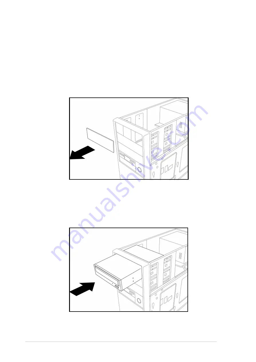
1. Remove the cover of an empty 5.25-inch external drive bay.

2. Carefully insert the CD-RW drive into the bay and push it inward until it

is flushed to the chassis front panel. The holes on the sides of the drive
should align with the holes on the drive bay.

Summary of Contents for 40x/12x/48x CD-RW Drive CRW-4012A

Page 1: ...1 40x 12x 48x CD RW Drive CRW 4012A User s Manual ...

Page 2: ... PRODUCT Product warranty or service will not be extended if 1 the product is repaired modified or altered unless such repair modification of alteration is authorized in writing by ASUS or 2 the serial number of the product is defaced or missing The product name and revision number are both printed on the product itself Manual revisions are released for each product design represented by the digit...

Page 3: ... 15 Installation 16 System Requirements 16 Setting the Jumper Terminals 17 Installing the CD RW Drive 18 Connecting the Drive Cables 20 Installing the Device Driver 21 Installing the CD RW Software 21 CD RW Drive Basics 22 Placing a Disc into the Drive 22 Ejecting a Disc from the Drive 23 Using the Emergency Eject Pinhole 24 Using Compact Discs 25 Cleaning a Disc 25 Handling a Disc 25 Technical In...

Page 4: ...pment does cause harmful interference to radio or television reception which can be determined by turning the equipment off and on the user is encouraged to try to correct the interference by one or more of the following measures Reorient or relocate the receiving antenna Increase the separation between the equipment and receiver Connect the equipment to an outlet on a circuit different from that ...

Page 5: ...UTER INTERNATIONAL America Address 6737 Mowry Avenue Mowry Business Center Building 2 Newark CA 94560 USA General Fax 1 510 608 4555 General Email tmd1 asus com Technical Support Support Fax 1 510 608 4555 General Support 1 502 995 0883 Notebook Support 1 877 918 ASUS 2787 Web Site www asus com Support Email tsd asus com ASUS COMPUTER GmbH Europe Address Harkortstr 25 40880 Ratingen BRD Germany Ge...

Page 6: ...epair the drive Opening the drive may result to exposure to laser radiation Do not use or place this device near magnetic fields televisions or radios where there is interference that may affect the performance of the drive Do not place this device in areas where there is direct sunlight high humidity or damp condition Do not place this device in an unstable position or in one that vibrates ...

Page 7: ... cleaner to dilute the solvent to easily wipe it from the device Try not to interrupt the supply of power while the device is in reading or writing mode Do not place damaged or warped discs inside the device A warped disc may break while in use and damage the device Do not place discs into the device immediately if they came from a cold environment specially during cold seasons Wait until the disc...

Page 8: ... any of the items is damaged or missing contact your retailer immediately ASUS CRW 4012A internal IDE drive IDE cable Mounting screw package Wire cable Emergency eject pin ASUS High Speed CD R blank disc ASUS High Speed CD RW blank disc User s Manual Multi language Quick Installation Guide Bundled software CD NOTE The above items are available in retail boxes only ...

Page 9: ...Link Technology Double Dynamic Suspension System II DDSS II Zone CLV Recording Technology Data buffer size 2MB Application discs 12cm or 8cm diameter 1 2mm thick CD Audio CD ROM CD ROM XA CD I Mixed Mode CD ROM Photo CD CD Extra Video CD CD Text DVCD CD G Karaoke CD I trax Bootable CD Recording form Orange Book Part 2 3 Disc at once Track at once Session at once Packet write Overburn DAO RAW mode ...

Page 10: ...exible speeds The ASUS CRW 4012A drive employs this technology that allows automatic recording speed adjustment based on the recording media In addition to the fact that there are low and high quality recording media various other factors such as dye layer temperature humidity dust fingerprints etc affect the recording characteristics of CD R and CD RW discs Due to these factors some discs may not...

Page 11: ...logy provides a seamless combination of flexibility and ultra reliable recording quality FlextraLink incorporates a flexible strategy that prevents buffer underrun problems caused by an empty data buffer This CD RW drive technology allows continuous monitoring of the data buffer status during the write process Once the available data drops to approximately 1 of the total buffer capacity the drive ...

Page 12: ...p to over 10 000 rpm of the new 50X drives In addition the DDSS II stabilizes the pick up head of the drive in both horizontal and vertical directions making tracking and focusing even more precise Like the DDSS the DDSS II vibration absoption structure contains a dynamic mass that can absorb the vibration caused by high revolution of spindle motor However the DDSS II moves the dynamic mass to be ...

Page 13: ...four zones partitioned from the inner to the outer area in a disc When using the Zone CLV the recording speed in Zone 1 is 16X then increases to 20X speed in Zone 2 after t1 time In Zone 3 the recording reaches 24X speed after t2 time In Zone 4 the recording speed reaches 32X after t3 The maximum recording speed of 40X is attained in Zone 4 after t4 time t1 t2 24x Zone1 20x 16x 32x t3 Zone2 Zone3 ...

Page 14: ...s while data is being written on the disc recording 4 Emergency eject pinhole In cases when you cannot eject a disc from the drive using the eject button due to power failure or software problems insert a pin or a paper clip into this hole to manually eject the tray and the disc 5 PLAY SKIP button This button has two functions If the drive is idle pressing this button will start playing an audio d...

Page 15: ...llow you to select either Master Slave or Cable Select mode for the CD ROM device 4 IDE connector This connector is for a 40 pin IDE cable to connect the drive to the IDE interface on the motherboard 5 Power connector This DC connector is for a 4 pin power cable from the system power supply NOTE The jumper pins on the leftmost part of the rear panel are factory test pins DO NOT cover these pins wi...

Page 16: ...ory 128MB is recommended An empty 5 25 inch external drive bay HDD empty storage capacity of 100MB or more Average seek time 20ms or less Transmission rate 2 MB s or more NOTE Do not use a hard disk that calibrates thermally during operation Recommended media 40X CD R Acer CMC Kodak LeadData Mitsui Nan Ya Prodisc Ritek TDK CD R AMT CMC Hitachi Kodak Maxwell Mitsubishi Chemical Philips Princo Prodi...

Page 17: ...rive as a secondary master drive This is possible only if your computer supports four IDE devices The hard disk in the computer is set as Primary Master Slave Mode Cover the two pins labeled SLAVE to set the CD RW drive as a slave device if your computer supports only two IDE devices If your computer supports four IDE devices this setting sets your CD RW drive either as a Primary Slave or a Second...

Page 18: ...computer manual for specific instructions on opening the chassis and installing drives 1 Remove the cover of an empty 5 25 inch external drive bay 2 Carefully insert the CD RW drive into the bay and push it inward until it is flushed to the chassis front panel The holes on the sides of the drive should align with the holes on the drive bay ...

Page 19: ...the drive package Use two screws on each side of the drive IMPORTANT Depending on the space on your chassis you may need to connect the drive cables before securing the drive into the chassis For cable connections proceed to the following section Connecting the Drive Cables ...

Page 20: ...re connect an audio interface cable to the 4 pin analog audio connector on the rear of the drive Connect the other end of the audio cable to the connector on the sound card or on the 4 pin CD connector on the motherboard CAUTION All the cable plugs are slotted so that they fit in only one orientation If a plug does not fit in completely try reversing it DO NOT use too much force when fitting the c...

Page 21: ... you installed and automatically looks for the appropriate driver 3 Follow the screen instructions to install the driver Installing the CD RW Software The ASUS CRW 4012A drive supports the following software applications By AHEAD software gmbh Nero Burning ROM In CD Wave Editor Cover Designer By Microsoft Corporation Media Player CD Player Active Movie By Kodak Kodak Photo CD Player V2 0 or higher...

Page 22: ...ual CD RW Drive Basics Placing a Disc into the Drive 1 Press the eject button on the front of the drive to eject the tray 2 When the drive tray ejects out of the drive place the disc on the tray with the label printed side up ...

Page 23: ... to eject the tray 2 Carefully remove the disc from the tray 3 Press the drive eject button or lightly push the center of the drive tray to load the tray back into the drive NOTE If you are using a 12 cm disc place it on the tray making sure that it fits the outer circular border This border helps hold the disc in place If you are using an 8 cm disc place it on the inner circular border on the tra...

Page 24: ... malfunctions 2 Carefully pull the tray out and remove the CD CAUTION Use the manual method only as a last resort when the eject button does not work Make sure that you have turned off your computer before ejecting the drive tray Follow these steps to eject the drive tray using the emergency pinhole 1 Insert a paper clip or any pointed rod small enough to fit into the emergency pinhole CAUTION Do ...

Page 25: ...ection when using compact discs These instructions will help you avoid damaging the discs and your CD RW drive Cleaning a Disc Spray the disc with compressed air for about five seconds to get rid of the dust on a disc Handling a Disc Hold a disc by the edges Do not touch the disc surface ...

Page 26: ...P Read mode 44 5 dB TYP Microphone located 50cm in front of the drive 120cm above the drive at 30 angle Reliability MTBF 100 000 power on hours ODC Read 20 of power on time ODC Write 1 of power on time Mean Time To Repair MTTR 30 minutes Electrical and Audio Specifications Power Source Voltage 5V DC 12V DC Tolerance 5 10 Ripple 150m Vpp 300m Vpp Rating 900mA 1500mA I O Terminal Power connector 4 p...

Reviews: