background image


When you open the carton, you will find the below spare parts. 


#26 Safety Key 1PC 

#36 Silicon Oil 1PC 


#91 MP3 Line 1PC 

#97 Power Cord 1PC 


Tools & Hardware 

Summary of Contents for 8730G

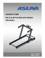
Page 1: ...1 ASUNA 8730G GOLD SLIM FOLDING MOTORIZED TREADMILL...

Page 2: ...ition and accounted for During the assembly process please be sure to follow each step accordingly as it has been explained within this manual WARNING During assembly it is recommended that all bolts...

Page 3: ...id flat level surface with a protective cover for your floor or carpet To ensure safety the equipment should have at least 8 feet 240CM of free space behind it and 2 feet 60CM on each side Do not plac...

Page 4: ...Exploded Drawing 1...

Page 5: ...Exploded Drawing 2...

Page 6: ...r Ring 2 33 L R Rear Foot Cover 2 11L R Side Fixing Hook 2 34 L R Rear End Cap 2 12 L R Aluminum Alloy Side Rail 22 75 1442L 2 35 L R Side Foot Cover 2 13 L R Side Rail Insert Sheet 7 4 79 7 1288L 2 3...

Page 7: ...8 Washer 9 16 T1 6 3 56 Screw M4 8 1 79 Washer 9 23 T1 6 4 57 Screw M4 15 2 80 Upper Wire M10 45 1 58 Screw M4 10 2 81 Wrench 8 1 12 3 T2 4 59 Screw M5 8 8 82 Wrench 4 1 4 4 T1 0 1 60 Screw M5 10 10 8...

Page 8: ...00 Switch 1 94 Magnetic Ring 2 101 Single Wire Red 200mm 1 95 O shape Ring 4 102 Single Wire Black 200mm 1 96 Meter Keyboard 1 103 Single Wire Grounding Wire 400mm 1 97 Power Cord 1 104 Screw M5 10 12...

Page 9: ...When you open the carton you will find the below spare parts 26 Safety Key 1PC 36 Silicon Oil 1PC 91 MP3 Line 1PC 97 Power Cord 1PC Tools Hardware...

Page 10: ...t No 2L No 2R using Tool No 38 STEP 2 Hold the position P of Meter Bracket Horizontal Tube No 4 and lift the Left Right Upright No 2L No 2R Tighten 2 Nuts No 6 to the Left Right Upright No 2L No 2R us...

Page 11: ...he treadmill Insert the Safety Key No 26 The assembly is complete STEP 3 Stand in front of the treadmill Turn the Pad Bracket No 16 upward as seen in drawing A then pull it slightly to the left as sho...

Page 12: ...to the right as shown in drawing A Then turn it down as shown in drawing B Turn the Foam Handrail No 3L No 3R Loosen 2 Nuts No 6 from Left Right Upright No 2L No 2R using the Tool No 38 Hold the posit...

Page 13: ...Tighten 2 Nuts No 6 to Left Right Upright No 2L No 2R using the Tool No 38 Then put the Tool No 38 back into place...

Page 14: ...ove steps are finished hold the Meter Bracket Horizontal Tube No 4 Place one foot on the front base and tilt the treadmill towards you until the Transportation Wheels No 44 on the front base touch the...

Page 15: ...olded Standing Size INCHES 62 2 L 30 3 W 5 4 H Rating 930W Running Size INCHES 49 2 L 17 7 W Motor Spec HP 2 5HP PEAK N W LBS 95 Input Volt V 110 120V Max User Weight LBS 220 Operating Temperature 0 8...

Page 16: ...and has a grounding plug that looks like the plug illustrated in sketch A Make sure that the product is connected to an outlet having the same configuration as the plug No adapter should be used with...

Page 17: ...you may step onto the belt SAFETY NOTE 1 We recommend that you maintain a slow speed at the beginning and hold the handrails until you become familiar with the treadmill 2 Insert the magnet end of the...

Page 18: ...unctions A Start Pause Press this button to start the treadmill When the treadmill is in operation press this button to pause the treadmill B Stop When the treadmill is running press this button to st...

Page 19: ...ing Mode This system has a power saving function In standby mode if there is no button command inputted within 10 minutes the system will enter power saving mode Press any button to start the system b...

Page 20: ...r main motor fault E03 No speed sensor signal with speed sense driver E04 Incline self checking E05 Overcurrent protection E06 Usually it is because motor has an open circuit E08 Storage 24C02 fault w...

Page 21: ...ical components and underneath the running belt WARNING Remember to unplug the treadmill from the electrical outlet before removing the motor cover Remove the motor cover and vacuum underneath at leas...

Page 22: ...ty Key No 26 and unplug the power Turn the right side adjusting bolt clockwise using Tool No 38 Turn on the treadmill and watch the Running Belt No 22 to see if it is centered Repeat the above steps u...

Page 23: ...ly wipe the lubricant over the Running Board No 21 Repeat this process for the other side The moving parts should turn freely and quietly Abnormal moving parts will affect the safety of the equipment...

Reviews: