


ABOT4001 REV1
BATTERY POWERED CRIMP TOOL
DATASHEET
________________________________________________________________________________________________
ABOT4001 rev1-DS
©2014 Astro Tool Corp., All Rights Reserved Page 7 of 8
REV. A
3/3/2016
Astro Tool Corp.
21615 SW Tualatin-Valley Hwy. Beaverton, OR 97003
Phone: 503-642-9853 Fax: 503-591-7766 Email: [email protected]
Trouble Shooting
Before You Begin
1.
Make sure that the battery is charged. Recheck the
battery after several minutes to make sure the
battery is holding its charge.
2.
Use a nonflammable contact cleaner or pencil eraser
to clean the electrical contacts on the battery and
crimp tool.
3.
Reinstall the battery and check the tool again.
Problem
Probable Cause
Probable Remedy
Tool is inoperative Dirt, contaminants, etc,
Clean tool.
in ram area of tool.
Crimping tool battery
Reform contacts.
contacts are damaged.
Tool components are worn
Return tool to Astro Tool.
or damaged.
Dies stop during
Oil level is low.
Return tool to Astro Tool.
operation.
Air in hydraulic system.
Pull trigger and hold
emergency release
button simultaneously.
Hold for approximately
10 seconds.
Tool loses oil.
Damaged internal seal.
Return tool to Astro Tool.
Battery Charger Operating Instructions
Operating Environment
The charger is designed for use in dry areas. All ventilation
slots must be kept free. If possible, keep away from heat
sources and out of direct sunlight; ambient temperatures in
excess of 95°F (35°C) may increase charging times
significantly.
AC Connection
Before connecting the charger, check that the AC supply
voltage is the same as what is indicated on the charger.
Specifications
Frequency=50Hz to 60Hz
Output Voltage=7.2 to 18VDC
Weight=2.2lb(1.0kg)
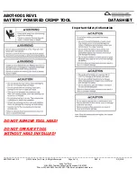
Safety Instructions
The charger is designed only for Li-ion and Ni-MH batteries
with voltages ranging from 9.6VDC to 18VDC and capacities
from 1.7Ah to 3.0Ah.
1.
Before using the charger, check power cord,
extension cable and connectors for any signs of
damage or aging.
2.
Do not open batteries or charger. Do not puncture
or expose to heat, as there is
RISK OF
EXPLOSION.
3.
Only store in dry areas. Protect from moisture and
dampness.
4.
Do not use if charger is defective and never insert
defective batteries.
5.
Observe the symbols on the charger’s rating plate.
6.
Do not throw old batteries into fire or dispose of as
domestic waste.
7.
Keep metal objects that could cause shorts away
from charger.
8.
Do not dismantle charger or batteries.
Operation
Green LED
If the charger is connected to the AC line the green LED will
flash repeatedly until a battery is installed for charging.
Charging a Battery
When a battery is inserted on to the charger the red LED will
illuminate and stay on while charging occurs.
The green LED will turn off while a battery is less than 80%
charged.
Both green and red LED’s will illuminate when a battery is
greater than 80% charged, but not yet fully charged.
When charging is complete, the red LED will turn off, and the
green LED will stay on.
If you leave a battery on the charger after it is charged, the
charger will switch to its trickle charge mode for 24 hours.


