


17
INSTALLATION AND OPERATION MANUAL
The circulation pump control thermostat SK2 (Fig. 6) is also located inside the front control panel and is not observable
from the outside. It has two functions: 1. Turn on the circulation pump when the water temperature in the boiler reaches
60° C, 2. Turn on the ventilator if the button 4 (Fig. 10) is in the 60-90° C position and the water temperature in the boiler is
higher than 60° C. Consequently, this thermostat will switch off both the ventilator and the circulation pump, when the water
temperature in the boiler drops below 60° C. To learn more about the control devices of the front control panel, please, refer
to the chapter “Kindling procedure of the boiler”.
• ReaR conTRol Panel
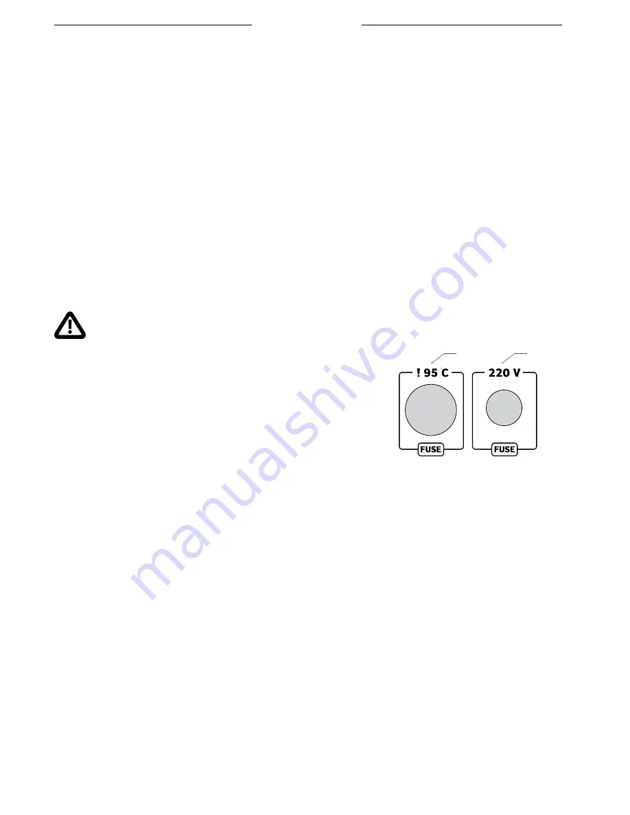
The following safety devices are installed in the rear control panel: thermal fuse 1 and electric fuse 2 (Fig. 10). The purpose of
the thermal fuse, otherwise called the maximum boiler temperature emergency thermostat, is to switch off the boiler ventilator if
water temperature in the boiler exceeds the maximum permissible 95°C due to unforeseen reasons. The temperature sensor of the
thermostat is installed in a dedicated sleeve 16 (Fig. 1). The burning intensity decreases when the ventilator is switched off and the
water temperature decreases. When the emergency thermostat trips, the lamp of the ventilator switch 3 on the front panel switches
off (Fig. 9) and the lighting indicator bulb 4 “Firing off” on the electronic regulator lights up (Fig. 11). In this case, it is necessary to find
out the causes of tripping and to remove them. After the boiler cools down, the emergency thermostat can be returned to its normal
operating mode. For this purpose, unscrew its cover and depress the red button.
The cause of overheating of the boiler and tripping of the emergency thermostat must be found
and removed. If this is not done, the risk of serious damage to boiler
equipment as well as hazard to human health and life remains. If the
user cannot locate and remove the cause of tripping of the emergency
thermostat, a professional servicing company must be consulted!
The electric fuse is designated to protect the elements of the electric circuit in case
the current in the mains exceeds 2 A. If the fuse is damaged, the boiler will not switch
on and its indicator lamps will not light. In this case, remove and replace the fuse.
The rear control panel of the boiler is grounded.
• PRePaRaTIon foR fIRInG
Before kindling the boiler, check the position of the ceramic chopper 2 in the lower combustion chamber: the edge of the
chopper must be in contact with the rear wall of the boiler (Fig. 2). Place two ceramic segments 3 (Fig. 2) on the chopper so
that they contact the walls of the boiler chamber.
Fill the heating system with water. The filling pressure should be 0.2 bar bigger than the hydrostatic pressure, yet it must
not exceed the operating pressure of the boiler. After filling the system with water, perform a visual check of the tightness of
the entire system. Perform it before kindling the boiler, then again after kindling and reaching the nominal operating mode.
Check if the heating system is properly deaerated.
• KInDlInG PRoceDURe of THe boIleR
Before kindling the boiler, check whether all requirements indicated in the section 1 are executed.
Open the damper of the upper flue 19 by pulling the handle 3 (Fig. 1) towards yourself. Open the door of the upper
combustion chamber, put dry smaller kindling wood pieces and paper on the ceramic bottom so that the paper protrudes into
the lower combustion chamber through the rectangular opening of the ceramic burner 1 (Fig. 2) – this way, it will be easy
to kindle the boiler through the lower combustion chamber. Put some of the easily flammable materials and larger pieces of
kindling wood and firewood atop. Load the wood without any large gaps at the top of combustion chamber. Bigger pieces of
1
2
fig. 11 Rear control panel
1. Thermal fuse ; 2. Electric fuse.


