background image

15

USB Video Diagnostic - 

If live video is not displayed on the PC monitor of 

the Astra System when the imaging software application is running, there could 

be a problem with the settings in the software application or with the handpiece . 

Perform the following USB Video Diagnostic


procedure to check that the Astra 

handpiece  is  working  correctly,  the  Handpiece  Cable  is  correctly  connected 

between the Astra System and the computer and the Astra System USB driver files 
are installed correctly on the PC . 

1 .  Go to the 

Start

 button and select 

Programs

 .

2 .  Select  the 

Astra 

program  option  and  click  on 

Camera  Demonstration 

Program

 and


observe that the Camera Demonstration Program screen opens .

3 .  Depending on the outcome of the diagnostic, perform one of the following: 

a .  If a live image is correctly displayed, exit from the application and make 

sure that the imaging software application is configured correctly .

b .  If a live image is not displayed, exit from the application and check the 

handpiece, Handpiece Cable and USB driver file installation .

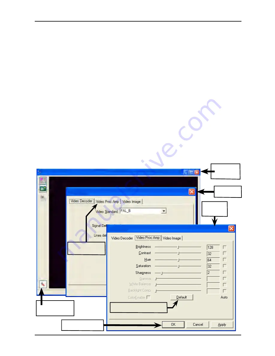
4 .  Reset the driver's video settings by performing the following:

a .  On  the  Astra  Demonstration  Program  screen,  click  the 

Properties 

button located on the lower left of the live image screen .

b .  On the Properties screen select the 

VIDEO PROC AMP


tab and then 

click the 

DEFAULT

 button . The image colors should now be correct . 

Click 

OK

 to close the Properties screen and exit from application .

SYSTEM CHECK

Properties 

Screen  

Video 

Proc Amp 

Screen  

Intraoral Camera Demonstration Program - Astra Intraoral Video Camera

Properties

Properties

Live 

Image 

Screen

Tab Opens Video 

Proc Amp Screen 

Default Button: Selects 

Default Settings as Shown 

Properties 

Button:Opens 

Properties


Screen

OK Button: Closes 

Properties Screen

Summary of Contents for D8000V

Page 1: ...Operator s Manual DVM C amera System USB Part Number D8000V ...

Page 2: ...4 System Check 15 Maintenance 16 Specifications 17 Physical Characteristics 17 Accessories 18 VISIX Imaging Software 18 Warranty 19 On Line Warranty Registration 19 ALLPRO Imaging has prepared this document as a guide to the proper use of the Astra DVM Camera System Review and follow the guidelines included in this Operator s Manual to ensure that your Astra System gives you the highest level of s...

Page 3: ...ecting any device to the Astra System that does not meet the equivalent safety requirements of the system may reduce the safety effectiveness of the Astra System Unplug the system components from power before performing cleaning procedures Contraindications None known Do Not Attempt Internal Service The interior of the camera is only accessible by removing hardware with tools and should only be op...

Page 4: ...service For product support and information on how to expand your Astra System contact your authorized ALLPRO Imaging dealer GENERAL SAFETY Markings The following terms or symbols are used on the equipment or in this manual to denote information of special importance AlertsuserstoimportantOperatingandMaintenance instructions Read included documents Indicates type BF equipment in accordance with UL...

Page 5: ...ed by the manufacturer There is no guarantee against damage arising where parts or accessories are used that are not supplied by the manufacturer Observe the usage and storage conditions The Astra System may only be operated using authorized software The manufacturer regard themselves as being responsible for the equipment with regard to safety reliability and proper functioning only if assembly r...

Page 6: ...lin es in clud ed in th e O pe ra to r s M an ua l to en su re yo ur As tra Sy ste m gi ve s th e hi gh es t leve l of se rv ice Ast ra Sy st em Key Pa rt s Id en tifica tion Ha nd pie ce Ho lde r wi th Ch air si de Ad ap ter Ca me ra Ha nd pie ce US B Ha nd pie ce Ca ble 10 fee t Ca me ra Ha nd pie ce Di sp os ab le Ca me ra Co ve rs Sa mp le Pa ck Operator sMa nual USBDeviceDriv ers Demonstratio...

Page 7: ...nd has a Type A USB connector for connection to a high speed high power 500 mA USB 2 0 port on the user s computer This cable carries all power video and keypad button control signals for the handpiece Handpiece Holder The Handpiece Holder can be fastened in a convenient location for safe storage of the handpiece when it is not in use In addition to storage the handpiece holder also has built in m...

Page 8: ... Intel 32 bit processor Microsoft Windows XP Professional 64 bit Edition with Service Pack 2 or later for an Intel 64 bit extended x64 processor Microsoft Windows Vista Business Enterprise or Ultimate with Service Pack 1 or later for an Intel 32 bit or an Intel 64 bit extended x64 processor Microsoft Windows 7 Professional Enterprise or Ultimate for an Intel 32 bit or an Intel 64 bit extended x64 ...

Page 9: ... Keypad Button Press and release to send a Button 1 command to the PC While the specific function performed depends on the setting of the video capture software application installed on the PC this command typically freezes and unfreezes the image that is displayed on the computer monitor 2 Bottom Keypad Button Press and release to send a Button 2 command to the PC While the specific action depend...

Page 10: ...stra System and the associated user supplied USB streaming video software application installed on the PC computer system This must be completed before the Astra System will operate properly Normally this program runs automatically when the CD is inserted into the drive for the first time If not run the setup program located in the root directory of the CD typically D Astra exe Install the Standar...

Page 11: ...pplied standard Handpiece Holder Refer to the illustration below and install the Chair side Adapter as follows 1 Insert Handpiece Holder Adapter 1 into the wide end of Grip 2 2 Press Grip 2 into the top of the chosen Handpiece Holder 3 Insert Expander 3 into the bot tom of Grip 2 4 Insert and push the Joint Connector Hex Bolt 4 into Expander 3 engaging the thread of Handpiece Holder Adapter 1 by t...

Page 12: ... the keyway of the mating Handpiece Cable connector 6 Insert straight into Handpiece connector until it securely snaps into place When transporting the complete Astra System handpiece and cable among patient operatories simply disconnect the USB connector end of the Handpiece Cable transport the system and reconnect to the new computer Make sure that the computer in the new operatory is using comp...

Page 13: ...ic layer and the bottom paper layer See D NOTE For optimum image clarity the optically clear section of the camera cover must be aligned with the camera lens by facing the camera light source section of the handpiece down toward the paper layer Disposable Camera Cover Installation Install a new Camera Cover on the Camera Handpiece for each patient as follows PRE OPERATION The Astra System should b...

Page 14: ...freeze ie capture the displayed image on the computer monitor screen Press and release the top keypad button again to unfreeze the displayed image 4 Press and release the bottom keypad button on the Camera Handpiece to save the captured image to the computer hard drive and then to return to a live image display 5 Repeat steps 2 through 5 as necessary 6 When imaging an X ray film on a light box dea...

Page 15: ...ve image is correctly displayed exit from the application and make sure that the imaging software application is configured correctly b If a live image is not displayed exit from the application and check the handpiece Handpiece Cable and USB driver file installation 4 Reset the driver s video settings by performing the following a On the Astra Demonstration Program screen click the Properties but...

Page 16: ... for possible defects as follows 1 Camera Handpiece a Check overall handpiece for chips cracks or other irregularities b Check the lens window for debris or spots c Check the connector socket for damage 2 Cables and Connectors a Check cables for damaged or deteriorated insulation kinking or twisting b Check connectors for loose bent or missing pins c Check that the quick disconnect plug end snaps ...

Page 17: ...CCD Format PAL Pixels 720 H X 576 V Exposure Control Automatic Illumination Ultra bright white LED lamps Image Normal not mirrored Operating Temperature 10 to 40º C 50 to 104º F Storage Temperature 0 to 70º C 32 to 158º F Humidity 10 to 90 non condensing Classifications Portable Continuous Operation Type BF Applied Part No mains connection Protection for Ingress of Water Ordinary per IEC 60529 Fla...

Page 18: ...are 5 Licenses ACCESSORIES VISIX IMAGING SOFTWARE Consider VISIX our new comprehensive digital imaging software application providing seamless integration with our digital imaging suite the Accent CCD Intraoral Sensor ScanX PSP Systems and Astra Intraoral Cameras Key Features Easy to learn Simple to use Acquire mount view and store images with just a few mouse clicks Customize images to personal p...

Page 19: ...RO Imaging Inc is not liable for indirect or consequential damage or loss of any nature in connection with this equipment This warranty is in lieu of all other warranties expressed or implied No representative or person is authorized to assume for us any liability in connection with the sale of our equipment Quickly and easily register the Astra Camera on line Just have your product model and seri...

Page 20: ...rity markets Thousands of ALLPRO Imaging products have been sold globally installed and serviced through our network of authorized dealers 100 Plus 2010 PolarisJ ScanX 12 ScanX 12 DVM ScanX Discover ScanX Duo ScanX Fit ScanX Quantum ScanX Scout ScanX Trek VisixJ 1295 Walt Whitman Road Melville NY 11747 3062 Website www allproimaging com Toll Free 1 800 247 8324 ...

Reviews: