background image

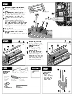
step 4

RADIO AND RECEIVER INSTALLATION

Cut a piece of #6727 servo tape and use it to 
attach your optional ESC and switch where 
shown.
Cut a piece of #6727 servo tape and use it to 
attach your optional receiver where shown.
Connect the ESC and steering servo to your 
receiver according to your radio or ESC 
instructions. Then connect the motor to your 
ESC.
Push your receiver wire through the built-in 
antenna mount. Slide the wire through the 
#6338 antenna and push the antenna firmly into 
the chassis antenna mount hole. Cap the other 
end of the antenna tube and wire with the black 
rubber cap.

TEAM KIT ONLY

If needed, remove the transponder mount and 
cut away all the gray areas as shown in 
illustration.
Attach the mount to the servo where shown with 

ESC

receiver

6338

3

step 5

BATTERY INSTALLATION

Install your battery pack. See 
which figure, at left or right, best 
represents your battery 
orientation.
Thread on the two #6916 
screws. Aim the body clip hole 
across the chassis. 
Add the #3848 foam spacer.
Add the #3853 battery hold 
down strap, orienting it up or 
down according to your battery 
pack design. Adjust the screws 
so the batteries are held tight, 
but you are still able to push the 

6916

6916

6916

6916

3853

3853

6332

6332

6332

6332

BAG I

REMOVE THESE 
PARTS FOR:
Steps 1-2

6917, qty 2
4-40 x 3/8 screw

1:1

6922, qty 2
4-40 x 1/2 screw

3897, qty 4
pivoting body mount

8874, qty 2
rear body post

6332, qty 8
body clip

8818

6922

3848

3848

3852, qty 1
foam bumper

6338

8818

6922

1:1

switch

3902

TEAM KIT ONLY

cut out gray areas

TEAM KIT ONLY

attach mount here

17

8818, qty 2
front body post

TOOLS USED

1/16"

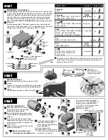
step 1

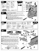
FRONT BODY 
POSTS

Attach each 
#8818 front body 
post to the front 
bumper with one 
#6922 screw.

Summary of Contents for RC10TC3

Page 1: ...rm bodies with matching Protoform decal Also includes Precision stainless steel rubber sealed ball bearings EACH KIT INCLUDES Pro Line std 12m Hex wheels tires Aluminum motor mount with a built in heatsink Carbide ball aSSOC differentials Adjustable caster camber toe in anti squat kickup Several tie rod mounting positions Foam bumper TC3 decal sheet Rear bumper HELPFUL TOOLS NOT REQUIRED Allen dri...

Page 2: ...u should have handy for that section 4 In some drawings the word REAR with an arrow indicates which direction is the rear of the car to help keep you oriented 5 The instructions in each step are ordered in the order you complete them so read the words AND follow the pictures The numbers in circles are also in the drawing to help you locate them faster 6 When we refer to left and right sides of the...

Page 3: ...n to the chassis with two 6292 screws Attach the 3863 front arm front mount with the F 2 molded into the mount to the 3851 bumper with one 6292 screw Slide the 3866 inner hinge pins through the 3860 front arms Slide the pins with the arms into the front arm rear mounts Align the front arm front mount and bumper with the two hinge pins and slide together Tighten it down with two 6292 screws By chan...

Page 4: ...rs from the inside of the gear with a hobby knife Add a generous amount of 6591 diff lube to the 3914 differential ring gear holes and push in the twelve large 6581 diff balls Then push back in the lube that came out Insert one 6909 bearing into the gear 3912 qty 2 short outdrive hub 3914 qty 2 differential ring gear 6573 qty 4 diff thrust washer 6575 qty 2 diff bolt cover 6575 qty 2 diff bolt 657...

Page 5: ...nch but not completely Rotate the diff hubs several times as you are tightening the bolt to check proper alignment of the parts Read step 9 carefully 7 8 6909 3912 long 6591 6579 6591 6579 3912 short step 5 FINAL OUTDRIVE ASSEMBLY Press the 3926 outdrive dust cap into the 3912 long outdrive Place one 3911 outdrive shim on both the long and short hubs Place one 3976 bearing over each outdrive hub 3...

Page 6: ...the 3917 gear adapter Add the 3919 large E clip 3919 C clip 3915 rear input shaft 3919 pin 3917 3919 large E clip 1 1 6288 qty 2 4 40 x 1 4 screw 7 step 8 Slide one 3977 or 6906 bearing and three 3911 input shaft shims onto the 3915 rear input shaft Install and center a 3919 dowel pin into the input shaft Slide a 3914 drive pinion onto the end of the input shaft Make sure the dowel pin aligns perf...

Page 7: ...sion case to the chassis with four 6292 screws step 10 step 11 step 12 FRONT TRANSMISSION ASSEMBLY Install the diff assembly and front input shaft assembly into the lower transmission case Add a small amount of 6591 diff lube to the front side of the ring rear and pinion gear Attach the 3910 upper transmission case to the lower case with six 6924 screws REAR TRANSMISSION ASSEMBLY LOWER HALF Attach...

Page 8: ...924 drive shaft REMOVE THESE PARTS FOR Steps 13 14 TOOLS USED 1 1 6924 qty 8 4 40 x 3 8 screw 3924 qty 1 driveshaft 3910 qty 1 upper transmission case 3917 qty 1 drive bearing cap step 14 REAR TRANSMISSION CASE Attach the 3910 upper transmission case to the lower case with six 6924 rear input shaft drive cup 6924 6924 6924 6924 6924 9 3 32 step 15 DRIVE BEARING CAP Align the 3917 drive bearing cap...

Page 9: ...95 qty 1 rear shock tower 1 1 1 1 1 1 7413 7413 7260 7260 3858 3858 7260 7260 6272 6272 3881 step 2 FRONT SHOCK TOWER ASSEMBLY Attach the 3881 front shock tower to the upper transmission case with three 6924 screws 3881 6924 6924 6924 step 3 REAR SHOCK TOWER ASSEMBLY Install the two 7413 screws through the outer holes on the 3895 rear shock tower Then thread on the 7260 nuts Attach the 3858 ball e...

Page 10: ...all end into the bottom of the 3876 steering block and add the 7260 plain nut Add a 6272 dust cover over ball the end Repeat steps for the right side installing the steering block ball end in the opposite way 1 1 RACER KIT ONLY 3977 qty 4 3 16 x 3 8 rubber sealed bearing TEAM KIT ONLY 6906 qty 4 3 16 x 3 8 PTFE sealed bearing 1 1 5 6588 7381 coupling 3887 or 3888 dogbone 7381 cross pin 10 7381 set...

Page 11: ... the right side See assembly picture at lower right 5 step 6 ATTACH REAR HUB CARRIER ASSEMBLY Place the left hub carrier between the arm holes as shown and add two 4187 spacers where shown Insert the 3866 rear outer hinge pin through the arm and hub carrier Thread in the 3862 5 40 set screw into the hub carrier Tighten down the set screw locking the hinge pin in place Insert the universal dogbone ...

Page 12: ...eat step for the right side Each chassis brace has a molded identification that indicates where it goes on the car as shown below 2 6924 6924 6923 3879 6923 6924 6924 3879 43 7 mm 38 8 mm LR LF BAG G REMOVE THESE PARTS FOR Steps 1 4 TOOLS USED 13 5407 qty 8 red O ring 6465 qty 4 shock piston 2 5423 qty 1 40 wt silicone oil 1 1 1 1 6469 qty 4 large O ring 6299 qty 8 E clip 1 1 1 1 TEAM KIT ONLY 845...

Page 13: ...il the piston is level with the top of the body The oil will bulge up above the shock body Fill The 6428 shock cap about halfway with oil and install onto the body Try to retain as much oil as possible during assembly The shaft will extend out as you tighten the cap down step 4 SETTING THE REBOUND Move the shock shaft in and out a few times an then push it all the way in It should be easy to push ...

Page 14: ...EAR SHOCK MOUNTING Add the 6473 shock bushing to the rear shock tower Push the shock cap over the bushing and add the 6472 nut Do not overtighten or the shock will bind Fasten the lower shock into the arm with the 6925 screw Do the other rear shock 4 6473 6925 BAG H REMOVE THESE PARTS FOR Steps 1 5 TOOLS USED 1 1 3858 qty 1 short special ball end black 3853 qty 1 battery brace 3930 qty 1 motor cam...

Page 15: ...7 7337 6917 6917 step 2 MOUNT THE SERVO Mount the servo to the chassis with two 7673 screws Twist 6274 ball cups onto 1356 blue turnbuckle or 3867 steel turnbuckle until you get the dimension shown Use needle nose pliers to attach the link to the ball 7673 1 56 in 6274 1356 or 3867 step 3 INSTALL YOUR MOTOR Attach the 3930 motor cam to the optional motor with two 3934 button head motor screws Inst...

Page 16: ...th ESC receiver 6338 3 step 5 BATTERY INSTALLATION Install your battery pack See which figure at left or right best represents your battery orientation Thread on the two 6916 screws Aim the body clip hole across the chassis Add the 3848 foam spacer Add the 3853 battery hold down strap orienting it up or down according to your battery pack design Adjust the screws so the batteries are held tight bu...

Page 17: ...hex adator 3951 qty 4 TC3 wheel 3955 qty 4 foam wheel insert 3955 3955 3950 6943 5 3 step 2 REAR BODY POSTS Place the rear 8874 body post to the front side of the rear shock tower Align the tab and hole and attach it with a 6917 screw Slide the 3897 pivoting body mount over the body post so its holes line up with the fifth hole from the top Adjust for proper hole later when you fit your body Slide...

Page 18: ... 5 1 9 47 MAINTENANCE Follow these steps to keep your car in shape for racing CHECK FOR FIT You should periodically check all the moving parts front and rear end suspension arms steering blocks steering linkage shocks and so on If any of these should get dirty or bind then your car s performance will suffer MOTOR MAINTENANCE Between runs inspect the brushes to ensure they are moving freely in the ...

Page 19: ...ng total caster in your car add the amount in the block carrier to the amount of kickup Example 2 of kickup kit standard and 0 block carrier equals total of 2 of caster Positive caster means the kingpin leans rearward at the top 0 block carrier 3868 2 block carrier 3870 4 block carrier 3872 FRONT FRONT TOE IN AND TOE OUT is adjusted by turning the steering turnbuckles Toe in will make your car eas...

Page 20: ...etting for all conditions However if you must make adjustments the following guidelines should help you The longer or higher the link the more traction and less stability The shorter or lower the link the less traction and greater stability Camber link possibilities for the rear tower and hub carrier Standard setup shown Camber link possibilities for the front tower Standard setup shown WHEELBASE ...

Page 21: ... would like more traction try the Pro Line 1091 S 3 compound tires with Pro Line tire inserts For racing conditions try the Pro Line 1089S2 S 2 slicks or 1089S3 S 3 racing slicks These optional tires are available from Pro Line SETUP SHEET for the TC3 is included Set up your TC3 with the standard settings at right then deviate from them in response to your track condi tions and driving style as no...

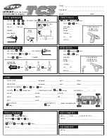
Page 22: ...ACEMENT Back Front Other __________________________________________________________ CHASSIS Std Carbon Fiber FRONT REAR DRIVE Std One way SPUR PINION ______ T ______T MOTOR ______________________________ BRUSH _______________________ SPRING _______________ RADIO _______________________________ SERVO ______________________ ESC ___________________ BODY ________________________________ WING _________...

Reviews: