background image

14 How to Change Your Code Number

It is advised that you’re new code should be between 4 and 8 digits including a 

combination of single and double press numbers for maximum security.

Please note

: The keypad has a double button press function and you are able to use the same digit twice. 

When the unit is being coded, if the green marker of the coding disc is in alignment with the centre line arrow on the cover plate it 

denotes that the button is set as a double press. 

If the red marker of the coding disc is in alignment with the centre line arrow it is set for a single press and if blue marker of the 

coding disc is in alignment with the centre line arrow it is not part of the code. 

The coding chamber is non-sequential so the code can be entered in any order. If for instance the unit was coded to 11234, 

the unit can be opened by entering 11432, 43211, 12314 etc... 

1

  To change the code, the unit will need to be removed from the door or done prior to fitting. WARNING - Please be careful when  


removing the codeGUARD shield, the security pin behind the shield is sprung loaded. The pin must be retained and re-inserted  


when re-fitting the shield to the door. See ‘Fitting the keypad’ section for details.

2

   Turn the keypad over and remove the shield and back plate (if fitted) so that the back of the coding chamber is visible. 


The internal lever is secured to the keypad by 2 x hex support posts and retaining screws. Turn the lever handle of the keypad to  


ensure that the coding chamber is reset before a new code is to be programmed. 

  With the coding chamber reset you will see that the coding discs are set to what the keypad is currently coded to. 


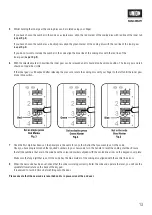
If for instance the unit is coded to 11234; the number 1 disc will have the green marker of the coding disc lined up with the   


centre line arrow on the cover plate (

as per fig.1

). 


The number 2, 3 and 4 will have the red marker of the coding discs lined up with the centre line arrow. 


All the other coding discs will have the blue line in alignment with the centre line arrow. 

  Choose your new operating code. To change how a button is set in the code – insert the code change tool (

as per fig.2

) into  


the small hole in the top of the inner gear and this allows this to be lifted upwards, this will expose a red line on the inner gear 


(

as per fig.2

).

12

Summary of Contents for Union CodeGUARD 5

Page 1: ...lutions CodeGUARD Fitting Guide UNION recommend that you read this guide to installing using and maintaining CodeGUARD before beginning any work and that it is kept in a safe place for future use English Version 1 0 BS8607 2014 A1 2016 Lic KM 690973 ...

Page 2: ...vide access when the correct code is entered Internal lever on backplate allows keyless egress at all times Must be installed with all of the components provided which cannot be modified or changed as this will invalidate the kitemark warranty and could reduce the security provided Is suitable for use on external doors Is supplied with fixings for timber and metal doors 45mm and 55mm thick Advisor...

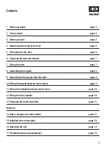
Page 3: ...7 8 Assembling the keypad page 8 9 Removing the transit pin from the latch page 8 10 Fitting the keypad external face of door page 9 11 Fitting the backplate internal face of door page 10 12 Fitting the lever handles page 10 13 Preparing the frame and strike page 11 Section 2 14 How to change your code number page 12 15 Exploded view of assembly page 14 16 Operating the unit page 14 17 Troubleshoo...

Page 4: ... fitted properly Give yourself time Please ensure you give yourself plenty of time to install this product correctly and adjust if required Please Note If at any point you feel you can not successfully complete the installation you can call our customer service helpline 0845 223 2124 After Installation Ensure end user has this document for future reference and re coding 4 ...

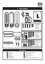
Page 5: ...Grub screws 2 x M4 x 40mm CSK 2 x M4 x 50mm CSK 2 x M4 x 60mm CSK 1 2 3 4 5 6 7 8 1 2 3 4 5 6 7 8 1 2 3 4 5 6 7 8 1 2 3 4 5 6 7 8 1 2 3 4 5 6 7 8 1 2 3 4 5 6 7 8 1 2 3 4 5 6 7 8 1 2 3 4 5 6 7 8 Code card 1 2 3 4 5 6 7 8 1 2 3 4 5 6 7 8 2 x Handle washers Shield fixing pack 2 x washers 8 x M3 fixing screws Button head bolt through fixings 2 x M6 x 40mm 2 x M6 x 50mm 2 x M6 x 60mm 1 2 3 4 5 6 7 8 Sc...

Page 6: ... to change the code from the factory setting please refer to how to change your code number instructions before installing the product 4 Determining the hand of the door The hand of the door is determined with the door in its closed position from the exterior or keypad side of the door as shown in the diagram below A Right hand door door opens inward push hinged on the right side C Right hand inwa...

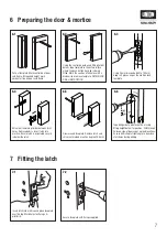
Page 7: ...s Remove debris Insert latch into mortice Ensure latch is orientated so snib is below the latch Draw around faceplate Remove latch and chisel out marked area to a depth of 4 5mm Tape drill guide to side face of door using fitting height datum for position Drill through holes on side of door as per marked locations Ensure drill is kept at right angle to door face at all times during drilling Insert...

Page 8: ...umber section Place the back plate flat on top of the shield ensuring the follower is visble through the circular cut out Secure back plate to shield with the 8 machine screws supplied Ensure that the screws sit flush with the face of the back plate Install hex support posts into the top and bottom of the key pad for stability Ensure these are screwed all the way to the surface 9 Removing the tran...

Page 9: ...6 button head bolt through fixings and washers Select appropriate fixings to suit door thickness Ie 40mm for 44 45mm door Insert the spindle through the lock and into the follower of the keypad Ensure that the flat end of the spindle is positioned at 5 past 7 from internal side of door 50mm Spindle 44 45mm doors 60mm Spindle 55mm doors Select the security pin required for the door thickness 44 45m...

Page 10: ...s over handle spindles to internal and external sides of the push button lock Fix handle pointing away from edge of the door Insert grub screw and secure with allen key supplied Test the operation of the handle If the handle does not return under its own spring pressure loosen the grub screw by of a turn until it springs back Repeat for other side of the door Once handles are securely fitted push ...

Page 11: ...t out template Mark centreline of frame at required height using the position of the installed latch as a guide Drill 2 holes 32mm dia to depth of 30mm as per drilling template Chisel out remaining timber between drill holes Clean out mortice Insert strike box to ensure hole accepts strike bring door and strike together to check alignment but do not close Adjust mortice if required 4mm Ø 32 30mm 4...

Page 12: ...ehind the shield is sprung loaded The pin must be retained and re inserted when re fitting the shield to the door See Fitting the keypad section for details 2 Turn the keypad over and remove the shield and back plate if fitted so that the back of the coding chamber is visible The internal lever is secured to the keypad by 2 x hex support posts and retaining screws Turn the lever handle of the keyp...

Page 13: ... the pressure rotate the coding disc with your finger to the left until the inner gear drops into position 7 Once the first digit has been set the principle is the same for any other button that you want to set in the code Once you have programmed all the required numbers in your new code turn the handle to reset the coding chamber Ensure that all the numbers that are in the code have the coloured...

Page 14: ...e to ensure the coding chamber is clear of any buttons that may have been pressed Enter the code and turn the handle the latch bolt will disengage and the door will open After the handle is operated the unit will reset and the code will need to be entered again in order to open the door 14 ...

Page 15: ... The latch bolt is not securing when the door is closed The strike plate keeps may not be adjusted correctly or the door may have swollen or twisted if in direct sunlight Check that there is a 3 5mm door gap between the lock and strike You can also adjust the strike plate keeps in accordance with the manufacturer s recommendations The inside handle or keypad lever does not return to the horizontal...

Page 16: ...is or any of the products in the UNION range please contact your Regional Sales Manager or the Customer Services Department ASSA ABLOY Security Solutions School Street Willenhall WV13 3PW Tel 0845 223 2124 Email info uniononline co uk www uniononline co uk J8607CG5 SS Version 1 0 July ...

Reviews: