10
BHL Trim
Installation Instructions
8200 Series
A8131F 08/19
Copyright © 2019, SARGENT Manufacturing Company. All rights reserved. Reproduction in whole or
in part without the express written permission of SARGENT Manufacturing Company is prohibited.
1-800-727-5477 • www.sargentlock.com
d
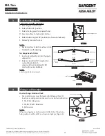
Install Inside Rose/Adapter Plate
Install inside adapter plate assembly using two
(2) machine screws. (Figure 24)
e
Install Inside BHL Rose Assembly
Attach inside rose assembly to inside adapter plate using four (4) security Torx screws. Tighten screws
evenly. (Figure 25)
Figure 25
IMPORTANT
Screw oriented towards latch
Security Torx Screws
LHR Inside Shown
f
Install Inside Lever Assembly
• Install inside spindle. (Figure 26)
• Install inside BHL lever assembly to
inside adapter plate assembly using
security Torx set screw.
IMPORTANT
• Line up rose screw with gap
on spring cartridge.
• Make sure machined end of
spindle seats into clutch adapter
before assembling lever onto rose. (Figure 26)
Notes
Inside of LHR shown.
Figure 24
01-1495
Machine Screw #8-32x5/8
Inside Adapter
Plate Assembly
LHR Inside Shown
Figure 26
Gap
Spindle
Security
Torx Set
Screw
Machined End
Rose Screw
Note position and
orientation of spindle.


