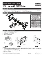


10X Line with BHW Trim
Installation Instructions
3
Copyright © 2022, ASSA ABLOY Access and Egress Hardware Group, Inc. All rights reserved. Reproduction in whole or in
part without the express written permission of ASSA ABLOY Access and Egress Hardware Group, Inc. is prohibited.
For installation assistance contact SARGENT
1-800-543-3658 • [email protected] • www.sargentlock.com
A8334 07/22
7
Cylinder Installation
IMPORTANT
Before installing cylinders:
• Use a flat blade screwdriver to rotate cam until the driver points
are in a 6 and 12 o’clock position. (Figure 8A)
Cylinder spacer should be installed “snapped”on to the cylinder
before installing into the outside trim assembly.
1. Install cylinder into the lever. (Figure 8B)
• Remove temporary construction core or plastic core. If keyed, use
Control Key. Rotate 15° and pull.
• Insert permanent core into lever with control key. Rotate 15° and
remove key.
a
Standard Cylinder (Figure 8)
b
Interchangeable or Removable Core (Figure 9)
Key
BHW Trim
Cylinder
Cylinder Spacer
Figure 8B
C
C
New Core
Figure 9
View into lock from
end of trim
12 o’clock drive point
6 o’clock drive point
Figure 8A
IMPORTANT
• Remove tailpiece from construction core and insert into new core. If using 7 pin cores,
insert the 7 pin tail piece that’s supplied with the lock, before installing the core into the
lock.
• For XC LFIC cores, snap-on retainer must be installed onto tailpiece. Tail and retainer
assembly will press fit onto back of core.
XC LFIC