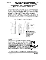
Assa Abloy Door Lock Installation And Operating Instructions Manual Download Page 3

Rev. A.1, 8/01 

Page- 3 

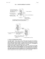
lines and knowledge of the gap between the springlatch and deadlatch pin are used to 
determine the vertical position of the springlatch plunger.  When 

this gap is greater than ¼”,


best reliability is obtained when the springlatch plunger position is centered on the springlatch.  

When the gap is smaller than ¼”,

 however, simply centering the springlatch plunger risks 

positioning the deadlatch pin too close to the springlatch plunger so the procedure is to position 
the edge of the springlatch plunger midway between the springlatch and deadlatch pin.  Figure 2 
illustrates these points. 


FIG. 2:  DETERMINING POSITION OF SPRINGLATCH PLUNGER 


2.4.2  ADJUSTING SPRINGLATCH POSITION 

Now that you have marked the unit with the correct position for the springlatch plunger, the 
actual adjustment must be performed.  Figure 3 shows the procedure. 

GAP BETWEEN
DOOR AND FRAME

CURVED LIP OF
MORTISE UNLATCH

SPRINGLATCH

DRAW LINES ON MORTISE
UNLATCH DENOTING TOP
AND BOTTOM OF SPRINGLATCH

DEADLATCH PIN
(MAY BE ABOVE)

MEASURE GAP
BETWEEN
SPRINGLATCH AND
DEADLATCH PIN

EXAMPLE OF SPRINGLATCH
PLUNGER CENTERED WITH
RESPECT TO SPRINGLATCH
POSITION (SHOWN BY
DRAWN LINES).  THE PLUNGER
SHOULD BE CENTERED WHEN
THE GAP BETWEEN THE
SPRINGLATCH AND DEADLATCH
PIN IS GREATER THAN 1/4"

WHEN THE GAP BETWEEN THE SPRINGLATCH AND DEADLATCH PIN
IS LESS THAN 1/4", SET THE BOTTOM EDGE OF THE SPRINGLATCH
PLUNGER MIDWAY BETWEEN THE SPRINGLATCH AND DEADLATCH
PIN.  (NOTE THAT THE DEADLATCH PIN MAY BE BELOW THE 
SPRINGLATCH AS IN THIS EXAMPLE, OR ABOVE IT) 

SPRINGLATCH
PLUNGER

SPRINGLATCH BOTTOM EDGE (EXAMPLE)

DEADLATCH PIN TOP EDGE (EXAMPLE)

MIDWAY POSITION

GREATER THAN 1/4" GAP

LESS THAN 1/4" GAP

Summary of Contents for Door Lock

Page 1: ...mp input surge 12 VDC 2 Amp input surge 24 VDC for 100 milliseconds and 600 mA 12 VDC or 300 mA 24 VDC during motor movement Operating Temperature 10 to 125 F FIG 1 MORTISE UNLATCH DIMENSIONS INCHES 1...

Page 2: ...ing for latch deadlatch location Note that the face of the Mortise UnLatch is protected by a removable film Leave this on during the pre mounting so as to preserve the metal finish against scratching...

Page 3: ...orrect position for the springlatch plunger the actual adjustment must be performed Figure 3 shows the procedure GAP BETWEEN DOOR AND FRAME CURVED LIP OF MORTISE UNLATCH SPRINGLATCH DRAW LINES ON MORT...

Page 4: ...cylindrical rubber bumpers which quiet the noise of a closing door but also have the effect of making the door close earlier If you have silencers and the door is still rattling too much contact the f...

Page 5: ...ing life but deliver the highest level of physical security obtainable in a mechanical latch To assure this security all mortise locks include deadlatching function This means that when the door is cl...

Page 6: ...WHICH FREEZES THE SPRINGLATCH FOR BEST SECURITY FIG 6 MORTISE UNLATCH IN OPERATION DEADLATCH PIN SPRINGLATCH SPRINGLATCH DEADLATCH PIN IN THE FIRST OPERATIONAL STEP THE DEADLATCH FINGERS WITHDRAW WHI...

Page 7: ...control device includes a timing function which will operate the Mortise UnLatch for a few seconds to permit each entry Like most conventional electric strikes the Mortise UnLatch is fail secure which...

Page 8: ...d on it Selecting thick wires to power the Mortise UnLatch will maintain strong torque even during start up The following table shows distances from the Mortise UnLatch to the power source and calls o...

Page 9: ...ustomer The replacement at SECURITRON s sole option may be the identical item or a newer unit which serves as a functional replacement In the event that the product type has become obsolete in SECURIT...

Page 10: ...and has consequently stalled the motor is not receiving enough power to operate the latch While the motor is in the process of stalling voltage to the processor will sharply drop and this can crash t...

Page 11: ...Rev A 1 8 01 Page ii TEMPLATE FOR CHISELING OUT A WOOD FRAME DOTTED LINE SHOWS AREA TO CHISEL OUT 1 7 8 DEEP FOR INSTALLATION IN WOOD FRAME 4 7 8 1 1 4 4 1 8 CENTER LINE...

Reviews: