


6
ED5000N (S)(A) Series Exit Device
Copyright © 2018 Corbin Russwin, Inc. All rights reserved.
Reproduction in whole or in part without the express written
permission of Corbin Russwin, Inc. is prohibited.
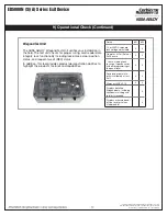
Typlcal ED5000N (S)(A) M802 Series Lock Application Diagram (24VDC Lock)
MODE 1: LED WIRE NOT USED = RED LED ‘ON’ WHEN POWERED
5) Wiring Diagrams (Continued)
*IMPORTANT: Pin 7 must be tied to earth ground in the access control panel.
Failure to follow proper ESD safe grounding procedures could lead to equipment failure.
Standard Application Shown - For Alternative Applications Contact 1-800-810-WIRE (9473)
READER NEG - Black, 1
READER POS - Red, 2
DATA 1 - White, 3
DATA 0 - Green, 4
RX (NO) - Orange, 5
RX (COM) - Blue, 6
*EARTH GROUND - Brown, 7
LED - Yellow, 8
LOCK NEG - Violet, 9
LOCK POS - Gray, 10
DPS (NC) - Pink, 11
DPS (COM) - Tan, 12
Not Used
120 VAC
Input
24 VDC
H N G
- +
24VDC Lock
Body Power
Power Supply
(By Others)
(-)
12VDC
(+)
DATA 1
DATA 0
RX
RX
Electrical Access
Control Panel
(By Others)
Use (NC) for Fail
Safe Operation
Lock Relay**
(NO) Fail
Secure
Operation
Black (Hot)
White (Neutral)
Gr
een (Gnd)
DPS
DPS
12 Conductor
ElectroLynx
Harness
From McKinney
QC12
Electric
Hinge
From
McKinney
**To prevent inductive “kickback”
on solenoid-operated lockset,
use of ‘flyback’ diode is required
(1N4001, 1N5400 suggested)
ULC-S319 compliance:
EAC power supply utilizing battery backup (30
minutes operation) is required.
Access 600 Reader
Electronics
Require 12 or 24VDC
UL294 Listed, Power
Limited Power Supply
(or UL603)
Reader Electronics Require 12 or 24VDC UL294 Listed, Power Limited Power Supply (or UL603)


