background image


Page 2 of 16         For more information visit website assaabloyesh.com         P/N: 3080006.016 Rev1 


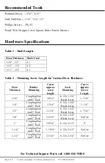
Recommended Tools 


Flathead Drivers — 3/32”, 3/16” 

Drill, Drill Bits — 1/16”, 3/16”, 1/2” 

Phillips Drivers — P0, P2 

Pencil, Wire Stripper, Level, Square, Ruler, Punch, Scissors 

 
Hardware Specifications  


Table 1 – Shaft Length 


Table 2 – Mounting Screw Length for Various Door Thickness 

Door 

Thickness 

Reader 

Mounting 

Cut to 

approx. 

screw 

length 

Lock 

Mounting 

Cut to 

Approx. 

Screw 

Length 

1/16” 

Coupling Nut 

and 3” Rod 

10/16” 

8-32 x 1-3/4” 

Break Away 

1-1/16” 

1/4" 

Coupling Nut 

and 3” Rod 

13/16” 

8-32 x 1-3/4” 

Break Away 

1-1/4” 

1/2” 

Coupling Nut 

and 3” Rod 

1-1/16” 

8-32 x 1-3/4” 

Break Away 

1-7/16” 

3/4” 

Coupling Nut 

and 3” Rod 

1-5/16” 

8-32 x 1-3/4” 

Break Away 

No Cut 

1” 

Coupling Nut 

and 3” Rod 

1-9/16” 

8-32 x 2-1/2” 

2” 

1-1/4” 

Coupling Nut 

and 3” Rod 

1-13/16” 

8-32 x 2-1/2” 

No Cut 

1-1/2” 

Coupling Nut 

and 3” Rod 

2-1/16” 

8-32 x 2-3/4” 

No Cut 


For Technical Support Please call 1-800-810-WIRE 

Door Thickness 

Shaft Used 

1/16” – 1/2” 

L1 

>1/2” – 1½” 

L2 

>1½” – 2¼” 

L3 

Summary of Contents for Aperio Series

Page 1: ...ings LED buzzer UHF polling period UHF status intervals and operations per day Actual battery performance will vary and depends on the factors above Operating Temperature 32 to 122 F 0 to 50 C HID mul...

Page 2: ...pprox screw length Lock Mounting Cut to Approx Screw Length 1 16 Coupling Nut and 3 Rod 10 16 8 32 x 1 3 4 Break Away 1 1 16 1 4 Coupling Nut and 3 Rod 13 16 8 32 x 1 3 4 Break Away 1 1 4 1 2 Coupling...

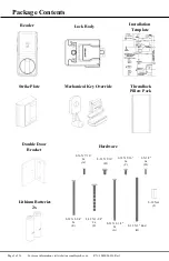
Page 3: ...ntents 6 X 1 2 6x D 6 32 X 5 16 3x C 8 32 X 5 16 B 2 56 X 7 16 2x A Reader Lock Body Strike Plate Installation Template Mechanical Key Override Hardware 8 32 X 2 1 2 2x G 8 32 X 2 3 4 2x E 8 32 X 1 3...

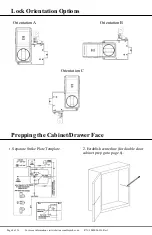
Page 4: ...bsite assaabloyesh com P N 3080006 016 Rev1 Lock Orientation Options Prepping the Cabinet Drawer Face 1 Separate Strike Plate Template 2 Establish centerline for double door cabinet prep go to page 6...

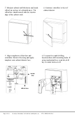
Page 5: ...set line should match with the interior edge of the cabinet wall 4 Continue centerline to face of cabinet drawer 5 Align template to offset line and centerline Remove backing and apply template onto c...

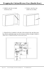
Page 6: ...oor 3 Align offset line on template to the edge of the stationary door and align center line with the established center line above Remove backing and apply template to cabinet face Continue with Step...

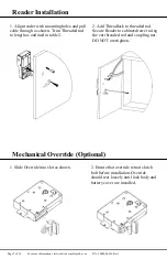
Page 7: ...Threaded rod to length as outlined in table 2 2 Add Threadlock to threaded rod Secure Reader to cabinet drawer using the cut threaded rod and coupling nut DO NOT overtighten Mechanical Override Option...

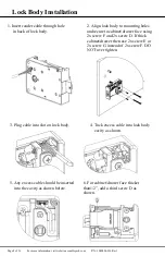
Page 8: ...oles andsecure to cabinet drawer face using 2x screw F and 2x screw D If thick cabinet drawer then use 2x screw E or 2x screw G instead of 2x screw F DO NOT over tighten 3 Plug cable into slot on lock...

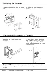
Page 9: ...onal Mechanical key override cam lock sold separately 1 Insert cam lock through the outside of the cabinet drawer face and secure with locking nut Insert the end of Cam into the mechanical override an...

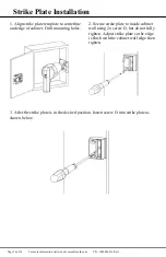
Page 10: ...template to centerline and edge of cabinet Drill mounting holes 2 Secure strike plate to inside cabinet wall using 2x screw D but do not fully tighten Adjust strike plate so the edge is flush with th...

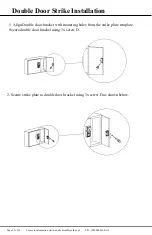
Page 11: ...sh com P N 3080006 016 Rev1 Double Door Strike Installation 1 Align Double door bracket with mounting holes from the strike plate template Secure double door bracket using 3x screw D 2 Secure strike p...

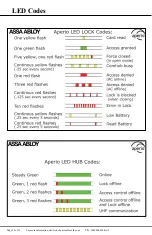
Page 12: ...Page 12 of 16 For more information visit website assaabloyesh com P N 3080006 016 Rev1 LED Codes...

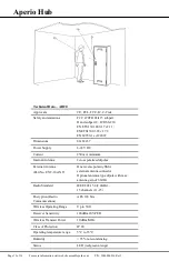
Page 13: ...rent 250 mA minimum Internal Antenna 2cross polarized dipoles External Antenna Part No EXT 10 ANT One reverse polarity SMA external antenna connector Optional antenna type dipole with max antenna gain...

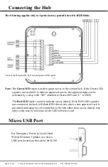
Page 14: ...be activated by a relay with NO attached to Green LED and C to GND The Red LED input is used to indicate access denied If the RED LED signal is not connected the lock will flash RED three times when...

Page 15: ...ment This device complies with Industry Canada license exempt RSS standards s Operation is subject to the following two conditions 1 this device may not cause interference and 2 this device must accep...

Page 16: ...est confrome avec Industrie Canada exempt de license RSS standard s Son fonctionnement est souimes aux deux conditions suivantes 1 cet appareil ne peut causer d interf rences et 2 cet appareil doit a...

Reviews: