background image


6410T0030_EN01 

2014-08-01 

Page 19 

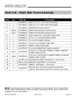
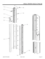
Parts List - Right Side Frame Assembly 

Item 

Qty 

Part No. 

Description 

4502T0014  Angle 5" x 5" x .375" Side Frame Right 

4511T0016  Tube 2" x 3" x .188" Side Frame Right 

4521T0687  Bracket Door Panel Lead-In 

varies 

8120T0039  Rubber Panel Retainer Assembly 4ft 

4  

varies 

8120T0040  Rubber Panel Retainer Assembly 6ft 

4904R0577  Light Curtain SG-14 D-profile Transmitter 

5499T0015  1/2-13 X .75 G8 SHOULDER SCREW 

5407T0019  1/2-13 G8 FLANGE LOCKNUT 

5402T0027  3/4-16 X 2.50 G8 HEX HEAD BOLT 

5499T0012  SPACER, END PLATE HOOK 

10 

5407T0020  3/4-16 G8 SERRATED FLANGE LOCKNUT 

11 

varies 

5402T0028 

5/16-18 X .75 G8 HEX FLANGED THREAD FORMING 
SCREW, ZINC PLATED 

12 

varies 

5402T0029 

5/16-18 X 1.50 G8 HEX FLANGED THREAD FORMING 
SCREW, ZINC PLATED 

13 

23-8003-00  PHOTOCELL GUARD, YELLOW P.C.  

(not shown)


14 

230031-4000  BRACKET, PHOTOCELL  

(not shown)


15 

4521T0260  SPACER, PHOTOCELL  

(not shown)


16 

1* 

8904R0002 

Photocell Set, Thru Beam (Sender & Receiver) 

(*set for both left and right side frames; not shown) 

NOTE:  

Quantities marked 

“varies” 

are dependent on the specific door configuration.  

Please contact ASSA ABLOY Entrance systems prepared with the door serial number 

available for more information. 

Summary of Contents for Albany RR1000

Page 1: ... ASSA ABLOY Entrance Systems AB 2014 All rights reserved Lodjursgatan 10 261 44 Landskrona SWEDEN 800 252 2691 www albanydoors us Albany RR1000 Owner s Manual Albany RR1000 6410T0030 Revision EN01 ...

Page 2: ...n in case of imitation or copying of the door system These operating instructions may not be reprinted or otherwise reproduced without the written consent of ASSA ABLOY Entrance Systems The general terms and conditions of ASSA ABLOY Entrance Systems are applicable ASSA ABLOY Entrance Systems reserves the right to make technical changes These operating instructions are an integral part of the door ...

Page 3: ... DOORS 11 INERTIA BRAKE RESET PROCEDURE 12 CURTAIN REPAIR 15 CURTAIN CLEANING 16 MANUAL HOIST USAGE 16 ELECTRICAL ADJUSTMENTS 17 TECHNICAL SUPPORT CONTACT INFORMATION 18 PARTS LIST 19 RIGHT SIDE FRAME ASSEMBLY 19 LEFT SIDE FRAME ASSEMBLY 21 DRUM TUBE ASSEMBLY 23 CURTAIN ASSEMBLY 24 BOTTOM BEAM ASSEMBLY 25 HEADER ASSEMBLY Direct Drive 27 HEADER ASSEMBLY Chain Drive 29 TOP ROLL MOTOR COVERS Direct D...

Page 4: ...e operating instructions are intended for trained qualified and authorized staff Only employees of the original equipment manufacturer or other staff trained by the original equipment manufacturer may install commission inspect maintain repair and dismantle the door This product has been designed and manufactured under consideration of a risk analysis according careful selection of the standards t...

Page 5: ...the likelihood and the potential severity of injury In addition a hazard sym bol may be used to represent the type of hazard DANGER indicates a hazard that if not avoided will result in death or serious injury WARNING indicates a hazard that if not avoided could result in death or serious injury CAUTION indicates a hazard that if not avoided might result in minor or moderate injury CAUTION when us...

Page 6: ...hat Installation first operation inspection servicing repair work and dismantling are only done by personnel that have been trained by the manufacturer Only to be operated by personnel that have been sufficiently assigned and au thorized to operate this door system The door must only be used for its intended purpose The door must be only operated in a functional perfect state and especially the sa...

Page 7: ...Button on the front of the panel is a momentary stop ONLY with the ACS 50 and MCC control panels The door will only stop for that cycle motion detectors floor loops or any activating device can activate the door To en sure that the door keeps from being activated use the rotary disconnect on the front of the panel When damage occurs to the door mechanically or electrically turn off opera tional po...

Page 8: ...ings Bottom Beam The bottom beam assembly is made from impact resistance fiberglass pultrusion profiles bolted to the front and rear face of the curtain A reversing edge sensor profile is connected to the bottom edges of the fiberglass and is surrounded by a rubber bottom edge weather seal Top Roll The top roll drum and idler are made from steel tubes with welded axle plates The idler tube also ha...

Page 9: ...in itself All Albany RR1000 doors are fitted with compliant protection of the main bottom edge The electric safety edge is tested prior to initiating downward movement and monitored permanently while the door closes The door will not initiate down ward movement if a fault is detected If a fault is detected during downward movement the drive unit reverses and opens the door immediately All doors ar...

Page 10: ...6410T0030_EN01 2014 08 01 Page 7 Technical Information ...

Page 11: ...g Edge Type wireless electric contact edge Photo Safety Type through beam photoeye or light curtain Counterbalancing none Life Length of Counterbalance N A Side Frame Construction self supporting heavy duty 3 8 painted steel Bottom Beam Construction high strength fiberglass pultrusion multiple layers depending on door width Top Roll Construction 8 5 8 diameter steel tube drum 6 5 8 diameter steel ...

Page 12: ...nd does not wrinkle Verify that the door opens fully slightly beyond the wall opening and does not open too far If the door does not seat against the floor properly or opens to the wrong posi tion refer to Setting Door Limit Adjustments in the applicable controls man ual If the door fabric has diagonal wrinkles the door fabric roll at the top of the door is not level and perpendicular to the side ...

Page 13: ...k condition of the safety edge and the cable 6 months or 50 000 cycles Check battery level in wireless transmitter should be 3 6V Check the condition and function of the crash system Check opening and closing position of the bottom profile Side Frame Check mounting hardware and condition of the profiles with attachments annually Remove dirt from the photocell optics clean if necessary Check condit...

Page 14: ...stalling the Inertia Brake A safety inertia brake is supplied on all chain drive doors This device engages and locks the top drum from turning if the maximum operation speed is exceeded The brake must be installed on the bracket on the non drive side of the header as sembly after the phase rotation has been verified This must be installed with the correct rotation direction Installing backwards ca...

Page 15: ...ced or adjusted An engaged inertia brake is indicated by the protrusion of the red indicator tab shown in the image below to the right NORMAL POSITION ENGAGED BRAKE Lock Out Tag out all electrical power supplied to the door be fore making any electrical installations or connections Also Lock out Tag out any equipment near the installation site if that equipment may be inadvertently operated into t...

Page 16: ...pward This may be accomplished using the manual chain hoist connected to the drive unit Then once in this position remove the two M10 bolts and clamping spacers shown being removed in the image below Next use the following diagrams to determine the proper course of action Damping Elements OK Safety Brake OK Proceed to Step 13 Damping Elements Damaged Safety Brake OK Proceed to Step 8 Damping Eleme...

Page 17: ... in cluded in the dampening plate repair kit order P N 6622T0023 Situation 6 shown on the previous page would be the only time that a repair kit would be needed Finally when all component replacements and adjustments have been made reset the inertia safety brake indicator in accordance with steps 14 and 15 as follows ...

Page 18: ...nter however it is not necessary to have the fabric 100 bare 4 Flip the curtain over to the other side of the rip or perforation and repeat steps 1 3 5 From the 1 8 thick piece of repair rubber cut some pieces to inlay into the pre pared areas Using a grinder with a sanding disc or a wire brush roughen up the inlay surfaces for bonding 6 Mix the adhesive as per the manufacturer s instructions and ...

Page 19: ...ASED PRODUCTS ON THE CURTAIN IF DONE THIS VOIDS ALL WARRANTY ON THE CURTAIN MATERIAL Clean curtain with a citrus based cleaner or a cleaner specifically designed for cleaning SBR EPDM rubber materials All cleaners are to be petroleum free and non caustic Dust may be removed with a cloth Harder dirt may be removed with water Dirt grease or oil on metal may be removed with a citrus cleaner Lock Out ...

Page 20: ...h or se rious injury Electrical Adjustments A qualified electrician must make all electrical mountings and connections in accordance with all applicable regulat ing authority electrical codes and standards Consult the control system manual supplied with the door for additional specifications and detailed instructions for installation and troubleshooting A full set of electrical schematics are supp...

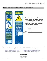
Page 21: ...tems Albany Sales Support sales us albany assaabloy com Toll free 800 ALBANY1 press 3 Albany Technical Support techsupport us albany assaabloy com Toll free 800 ALBANY1 press 1 DOOR ______________________ The door serial number is al ways required when calling in for technical support as sistance Please write this number below for conven ient future reference ...

Page 22: ... 2 50 G8 HEX HEAD BOLT 9 1 5499T0012 SPACER END PLATE HOOK 10 1 5407T0020 3 4 16 G8 SERRATED FLANGE LOCKNUT 11 varies 5402T0028 5 16 18 X 75 G8 HEX FLANGED THREAD FORMING SCREW ZINC PLATED 12 varies 5402T0029 5 16 18 X 1 50 G8 HEX FLANGED THREAD FORMING SCREW ZINC PLATED 13 1 23 8003 00 PHOTOCELL GUARD YELLOW P C not shown 14 1 230031 4000 BRACKET PHOTOCELL not shown 15 1 4521T0260 SPACER PHOTOCEL...

Page 23: ...Albany RR1000 Owner s Manual 6410T0030_EN01 2014 08 01 Page 20 ...

Page 24: ...50 G8 HEX HEAD BOLT 9 1 5499T0012 SPACER END PLATE HOOK 10 1 5407T0020 3 4 16 G8 SERRATED FLANGE LOCKNUT 11 varies 5402T0028 5 16 18 X 75 G8 HEX FLANGED THREAD FORMING SCREW ZINC PLATED 12 varies 5402T0029 5 16 18 X 1 50 G8 HEX FLANGED THREAD FORMING SCREW ZINC PLATED 13 1 23 8003 00 PHOTOCELL GUARD YELLOW P C not shown 14 1 230031 4000 BRACKET PHOTOCELL not shown 15 1 4521T0260 SPACER PHOTOCELL n...

Page 25: ...Albany RR1000 Owner s Manual 6410T0030_EN01 2014 08 01 Page 22 ...

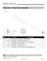
Page 26: ...IVE 2 0 varies 2 4 12 5403T0002 SCREW SHC 5 8 X 2 GRADE 5 5 12 5408T0016 LOCK WASHER 6 varies 4521T0241 STUB AXLE 2 0 7 1 4512T0012 8 63 X 18 WALL DOOR PANEL DRUM NOTE Quantities marked varies are dependent on the specific door configuration Please contact ASSA ABLOY Entrance systems prepared with the door serial number available for more information ...

Page 27: ...bber RR1000 Assembly 2 varies 8230TG031 Curtain Rubber RR1000 Safety Stripe Assembly Detail 3 varies 8230TG030 Curtain Rubber RR1000 Window Assembly Detail NOTE Quantities marked varies are dependent on the specific door configuration Please contact ASSA ABLOY Entrance systems prepared with the door serial number available for more information ...

Page 28: ...ety Receiver 2 4GHz 2 Channel FCC Cert 5 1 4521T0489 Wireless Mounting Bracket SS 6 varies varies 1 4 20 X 2 25 SOCKET HEAD PAN HEAD SCREW 7 varies varies 1 4 20 HEX NUT 8 varies 5408T0008 1 4 STANDARD WASHER 9 varies 5408T0009 1 4 STANDARD LOCK WASHER 10 2 5413T0012 8 32 RIVET NUT Zn 11 2 5404T0005 8 32 X 5 8 FLAT HEAD PH SCREW SS NOTE Quantities marked varies are dependent on the specific door c...

Page 29: ...Albany RR1000 Owner s Manual 6410T0030_EN01 2014 08 01 Page 26 Quantity and arrangement of fiberglass pultrusions is dependent on door width see note 1 1 ...

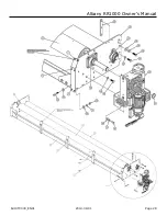
Page 30: ...408T0014 50 LOCK WASHER 10 16 5408T0015 50 STD WASHER 11 6 5402T0030 50 13 X 3 00 HEX HEAD BOLT 12 6 5407T0010 50 13 HEX NUT 13 6 5402T0004 63 11 X 2 00 HEX HEAD BOLT 14 24 5408T0012 63 STD WASHER 15 18 5408T0013 63 LOCK WASHER 16 16 5402T0033 63 11 X 1 75 HEX HEAD BOLT 17 2 5103T0004 BEARING FLANGED 2 BORE 2 BOLT 18 2 5103T0001 BEARING FLANGED 2 BORE 4 BOLT 19 3 5413T0001 RETAINING RING EXTERNAL ...

Page 31: ...Albany RR1000 Owner s Manual 6410T0030_EN01 2014 08 01 Page 28 ...

Page 32: ...8 1 4521T0987 Chain Drive Gearmotor Input Shaft 2 9 4 5413T0001 Retaining Ring External 2 10 2 5409T0008 KEY 1 2 X 1 2 X 4 UNDERSIZED 11 1 5409T0002 KEY 1 2 X 1 2 X 2 UNDERSIZED 12 2 4521T0898 Bracket Chain Drive Mount Half 13 6 5402T0004 63 11 X 2 00 HEX HEAD BOLT 14 15 5408T0012 63 STD WASHER 15 22 5408T0013 63 LOCK WASHER 16 4 5411T0009 63 11 HEX NUT 17 18 5408T0015 50 STD WASHER 18 10 5408T001...

Page 33: ...0001 BRAKE SAFETY 26 2 5103T0001 BEARING FLANGED 2 BORE 4 BOLT 27 2 5103T0004 BEARING FLANGED 2 BORE 2 BOLT 28 4 5402T0005 50 13 X 1 50 HEX HEAD BOLT 29 16 5402T0033 63 11 X 1 75 HEX HEAD BOLT 30 varies 5413T0013 RIVET NUT 5 16 18 X 0 690 STEEL ZINC PLATED 31 1 4521T0992 COLLAR INPUT SHAFT 2 32 1 5105T0017 CONNECTING LINK ANSI 80 CHAIN 33 4 5402T0032 3 8 16 X 2 HEX HEAD BOLT 34 2 4521T0991 BACK PL...

Page 34: ...6410T0030_EN01 2014 08 01 Page 31 ...

Page 35: ...Albany RR1000 Owner s Manual 6410T0030_EN01 2014 08 01 Page 32 ...

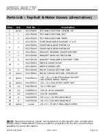
Page 36: ...R NON GEAR MOTOR LH 4521T0693 COVER NON GEAR MOTOR RH 6 1 4521T0691 BRACKET BEARING COVER SUPPORT 7 1 4521T0690 BRACKET GEAR MOTOR COVER 9 2 4521T0700 BRACKET REAR HOOD SUPPORT TUBE 10 1 4521T0683 MOTOR COVER RIGHT 4521T0692 MOTOR COVER LEFT 11 2 4521T0696 FRONT FASCIA SECTION END 12 varies 4521T0682 FRONT FASCIA SECTION CENTER 90 13 varies 5403T0013 312 18 x 75 BUTTON HEAD SOCKET CAP SCREW BLACK ...

Page 37: ...Albany RR1000 Owner s Manual 6410T0030_EN01 2014 08 01 Page 34 ...

Page 38: ...COVER CHAIN DRIVE FRONT RIGHT 4521T0985 COVER CHAIN DRIVE FRONT LEFT 10 1 4521T0981 COVER CHAIN DRIVE REAR RIGHT 4521T0986 COVER CHAIN DRIVE REAR LEFT 11 1 4521T0988 BRACKET GEAR MOTOR COVER CHAIN DRIVE SIDE 12 varies 5413T0013 312 18 x 690 STEEL RIVET NUT 13 varies 5402T0030 50 13 X 3 00 HEX HEAD BOLT 14 varies 5403T0013 312 18 x 75 BUTTON HEAD SOCKET CAP SCREW BLACK OXIDE 15 20 5408T0015 50 STD ...

Page 39: ...Albany RR1000 Owner s Manual 6410T0030_EN01 2014 08 01 Page 36 ...

Page 40: ...s specializes as a leading supplier of automatic entrance systems which ensure efficient flow of vehicles goods and people With our global presence comprehensive range of products and extensive service network we help customers to run their businesses reliably and securely over the long term ASSA ABLOY Entrance Systems is a business division of ASSA ABLOY ...

Reviews: